|
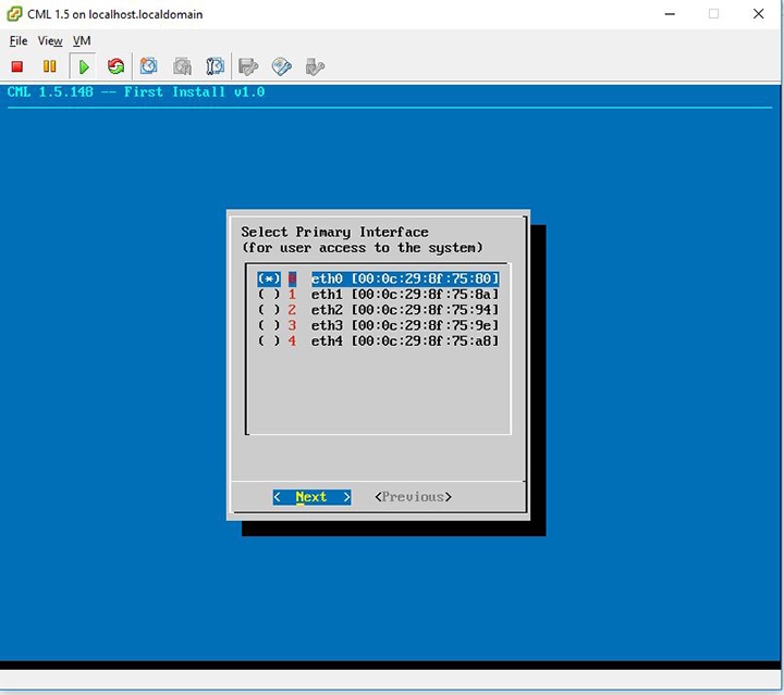
Flat Network Port
|
Eth1
|
Enter the Flat network port.
|
|
Flat Network Address
|
172.16.1.254/24
|
Enter the Flat network address.
|
|
Flat Network Address/Mask
|
172.16.1.0/24
|
Enter the Flat network address/mask.
|
|
Flat Network Netmask
|
255.255.255.0
|
Enter the Flat network netmask.
|
|
Flat Network Gateway IP Address
|
172.16.1.1
|
Enter the Flat network gateway IP address.
|
|
Flat Address Pool Start Address
|
172.16.1.50
|
Enter the Flat address pool start address.
|
|
Flat Address Pool End Address
|
172.16.1.253
|
Enter the Flat address pool end address.
|
|
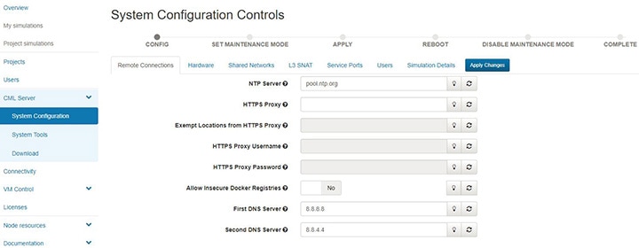
Flat Primary DNS server IP address
|
8.8.8.8
|
Enter the Flat primary DNS server IP address.
|
|
Flat Secondary DNS server IP address
|
8.8.4.4
|
Enter the Flat secondary DNS server IP address. Ensure you do not set the same address as you set for the primary DNS server
IP address.
|
|
2nd Flat Network Enabled
|
Unchecked
|
Use this option if a second Flat network, Flat1, is to be enabled.
|
|
2nd Flat Network Port
|
Eth2
|
Enter the name of the host's physical port used for the L2 Flat network, Flat1.
|
|
2nd Flat Network Address
|
172.16.2.254/24
|
Enter the IP address for the second Flat network, Flat1.
|
|
2nd Flat Network Address/Mask
|
172.16.2.0/24
|
Enter the Flat network address/mask for Flat1.
|
|
2nd Flat Network Netmask
|
255.255.255.0
|
Enter the Flat network netmask for Flat1.
|
|
2nd Flat Network Gateway IP Address
|
172.16.2.1
|
Enter the Flat network gateway IP address for Flat1.
|
|
2nd Flat Address Pool Start Address
|
172.16.2.50
|
Enter the Flat address pool start address for Flat1.
|
|
2nd Flat Address Pool End Address
|
172.16.2.253
|
Enter the Flat address pool end address for Flat1.
|
|
2nd Flat Primary DNS server IP address
|
8.8.8.8
|
Enter the Flat primary DNS server IP address for Flat1.
|
|
2nd Flat Secondary DNS server IP address
|
8.8.4.4
|
Enter the Flat secondary DNS server IP address for Flat1. Ensure you do not set the same address as you set for the primary
DNS server IP address.
|
|
Snat Network Port
|
Eth3
|
Enter the name of the host's physical port used for L3 Snat network, ext-net.
|
|
Snat Network Address
|
172.16.3.254/24
|
Enter the IP address for the CML host in the L3 Snat network.
|
|
Snat Network Address/Mask
|
172.16.3.0/24
|
Enter the Snat network address/mask.
|
|
Snat Network Netmask
|
255.255.255.0
|
Enter the Snat network netmask.
|
|
Snat Network Gateway IP Address
|
72.16.3.1
|
Enter the Snat network gateway IP address.
|
|
Snat Address Pool Start Address
|
172.16.3.50
|
Enter the Snat address pool start address.
|
|
Snat Address Pool End Address
|
172.16.3.253
|
Enter the Snat address pool end address.
|
|
Snat Primary DNS server IP address
|
8.8.8.8
|
Enter the Snat primary DNS server IP address.
|
|
Snat Secondary DNS server IP address
|
8.8.4.4
|
Enter the Snat secondary DNS server IP address. Ensure you do not set the same address as you set for the primary DNS server
IP address.
|

 Feedback