|
Name of
new subtype
|
Enter a
name for the new subtype.
|
|
Description of plugin
|
Provide
a description of the plug-in to be created.
|
|
Name of
management interface
|
Enter a
name for the management interface.
|
|
Names
of dummy interfaces
|
Enter
names for dummy interfaces, inserted between management interface and first
data interface.
|
|
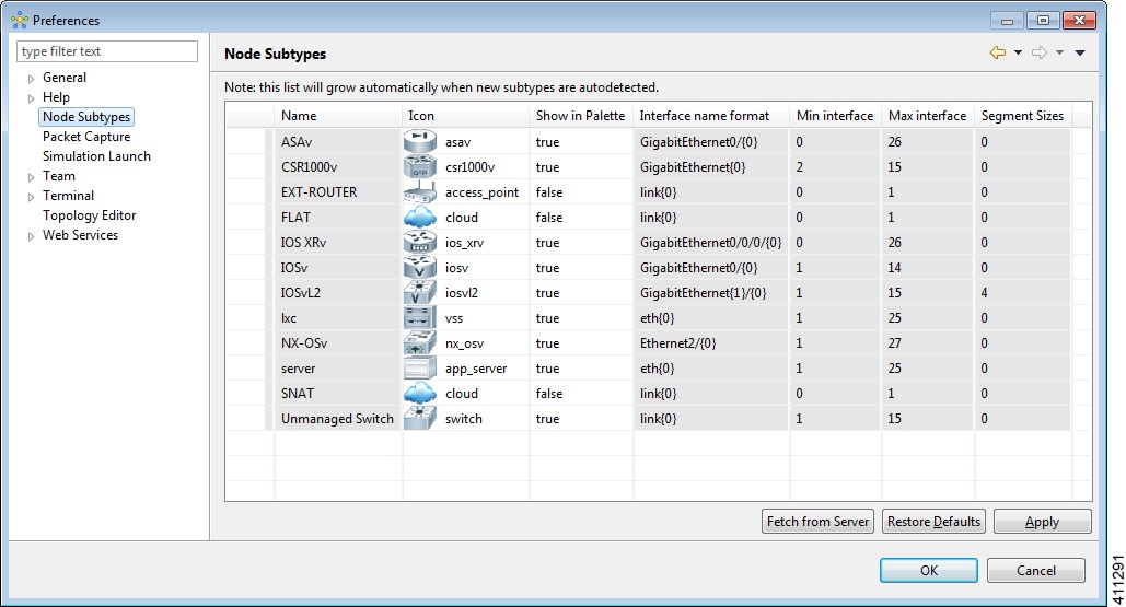
Pattern
for data interface names
|
Provide
the interface name format, for example, GigabitEthernet0/{0}.
|
|
First
data interface number
|
Enter a
valid integer for the first interface.
|
|
Max
count of data interfaces
|
Enter
the maximum allowed number of interfaces.
|
|
Number
of interfaces per LC
|
Enter
the permitted number of interfaces per line card (LC) allowed.
|
|
Number
of serial interfaces
|
Choose
the number of interfaces allowed. Options are
0,
1,
2,
3, and
4.
|
|
Protocol for network CLI
|
Choose
the type of console connection. Options are
Telnet or
SSH.
|
|
Make
VNC access available
|
Allow
VNC access. Enabled when the check box is checked.
|
|
Name
of icon for GUI
|
Enter
a name for the subtype icon that is displayed in the Cisco Modeling Labs
client.
|
|
Show
subtype on GUI palette
|
Allow
the subtype icon to be displayed in the Cisco Modeling Labs client. Enabled
when the check box is checked.
|
|
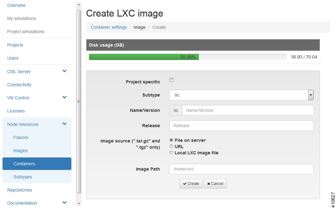
Configuration disk type
|
Choose
the type of configuration disk. Options are
cdrom,
disk,
cloud-init,
iso9660, and
vfat. For LXC subtypes, set to
lxc.
|
|
ISO
9660 Level in cdrom Disk
|
Choose
the ISO 9660 level in cdrom disk. Options are
2,
3, and
4.
|
|
Name
of file for config drive
|
Enter
a name for the configuration drive file.
|
|
Virtual interface model
|
Choose
a virtual interface model. Options are
e1000,
virtio, and
rtl8139.
|
|
Main
disk bus model
|
Choose
a main disk bus model. Options are
ide,
virtio, and
scsi.
|
|
RAM
(MB) allocated per node
|
Specify the amount of RAM (MB) to use for each node.
|
|
Number
of CPUs allocated per node
|
Choose
the number of CPUs to allocate per node. Value range is 1 to 16.
|
|
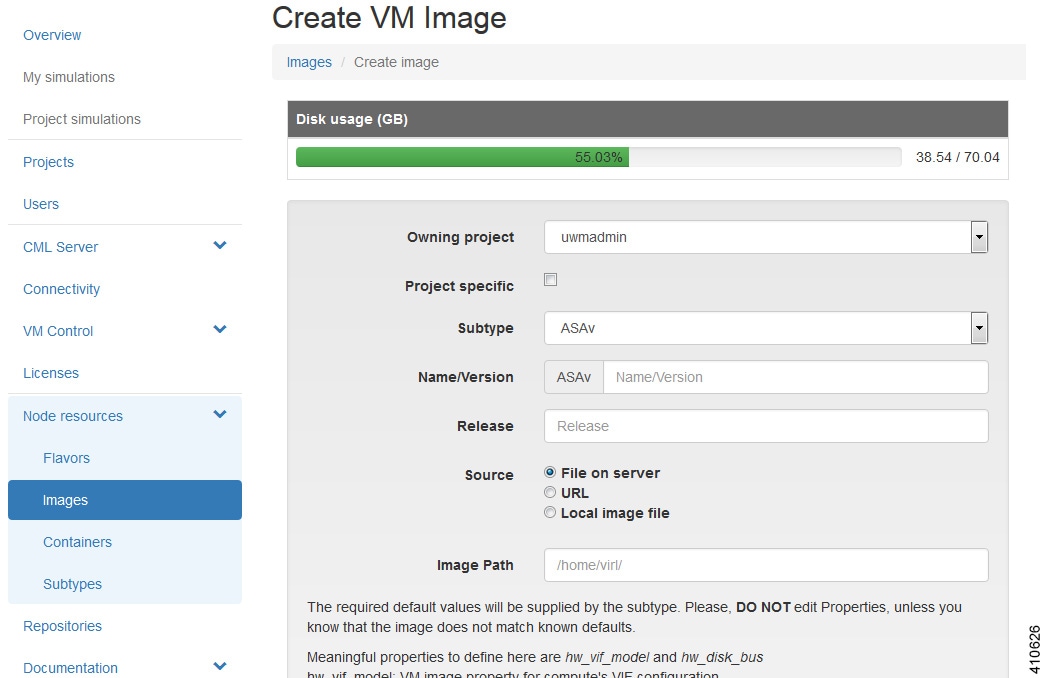
Extra
comma-separated image properties
|
Enter
any additional image properties, set on all images added for that subtype
through the Create New Image page.
|
|
Name
of default image
|
Enter
a name for the default image.
|
|
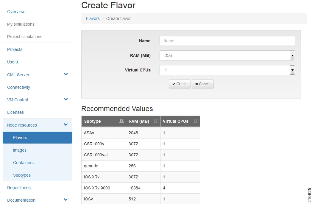
Name
of default flavor
|
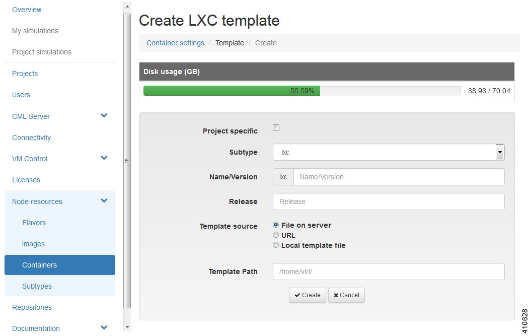
Enter
a name for the default flavor for VM-based subtypes and a default template name
for LXC subtypes.
|

 Feedback