Cisco Modeling Labs ISO Installation

Cisco UCS C-Series Server Installation

Cisco Modeling Labs can be run natively on Cisco UCS compute platform without an underlying ESXi hypervisor. Referred to as a bare-metal deployment, the installation requires the ISO installation file downloaded and accessible to the installation workstation. Bare metal deployments are exclusively supported on Cisco UCS products. The following UCS C-Series servers are supported:
  • Dual Socket servers for small to medium sized deployments:
    • Cisco UCS C220-M3

    • Cisco UCS C220-M4

    • Cisco UCS C240-M3

    • Cisco UCS C240-M4

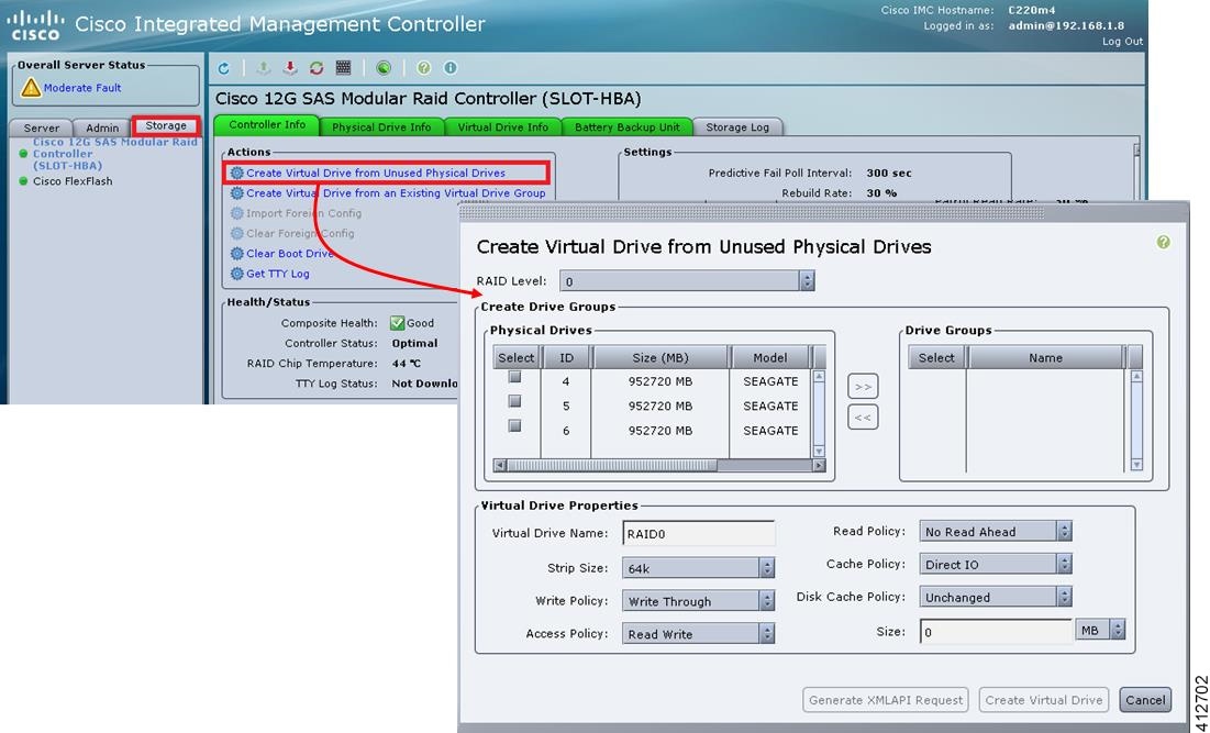
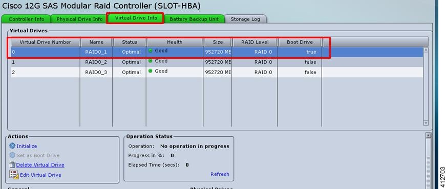
Cisco Modeling Labs has relatively modest storage requirements, with a 250GB capacity (or larger) Direct Attached Storage disk (DAS) recommended. RAID configurations are optional. When using a RAID configuration on the UCS C-Series server, the hardware based (MRAID module) version is the recommended method.

Storage Area Network (SAN) options are beyond the scope of this installation guide. SAN options are not supported for Cisco Modeling Labs bare metal deployments on Cisco UCS C-Series.

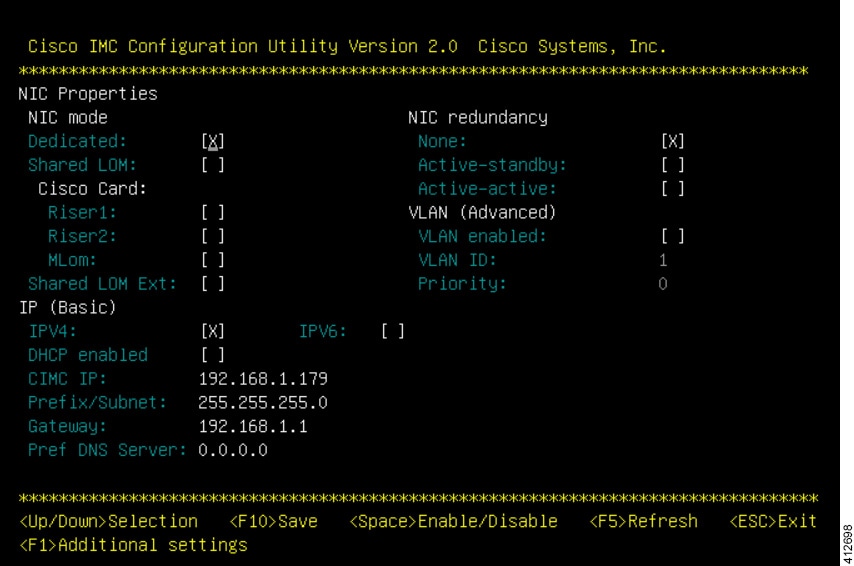
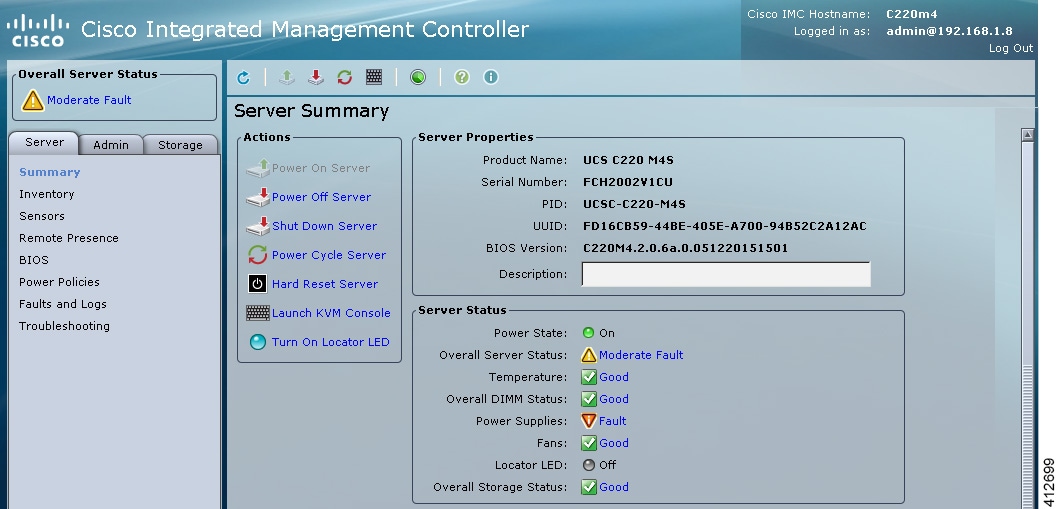
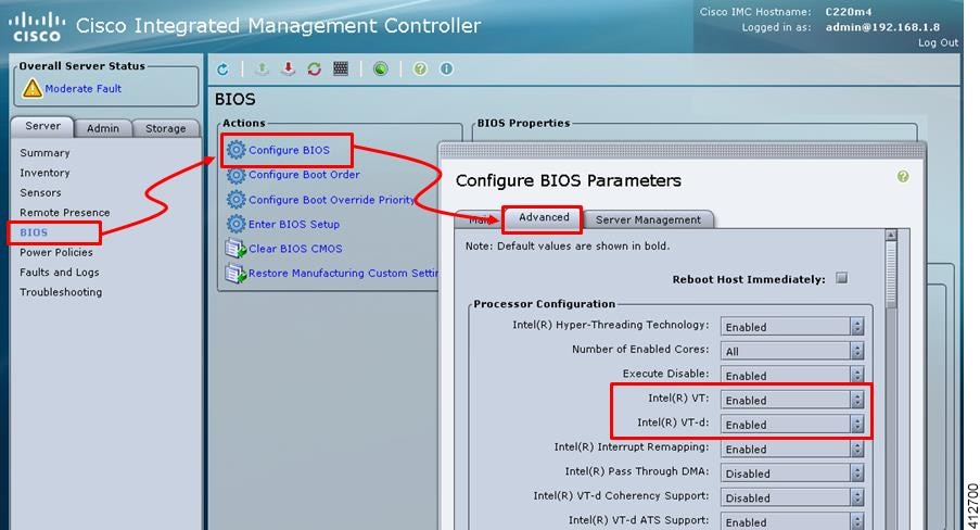
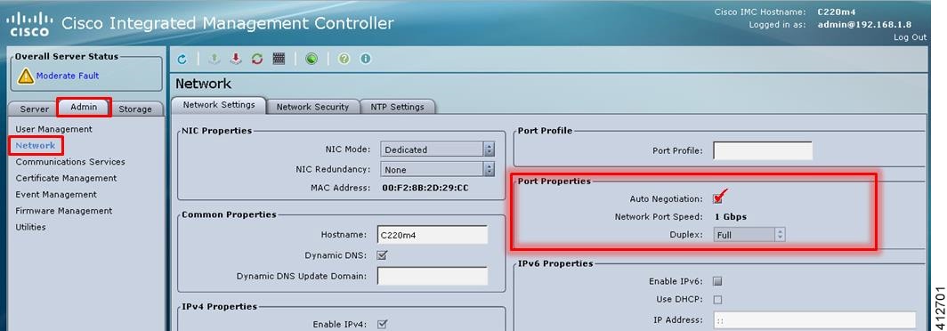
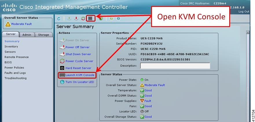
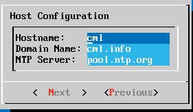
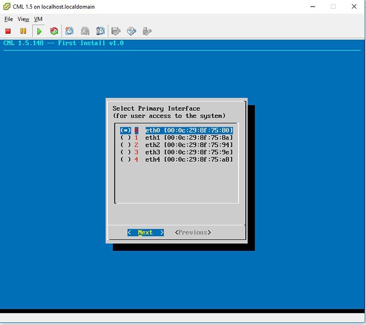
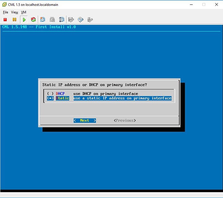
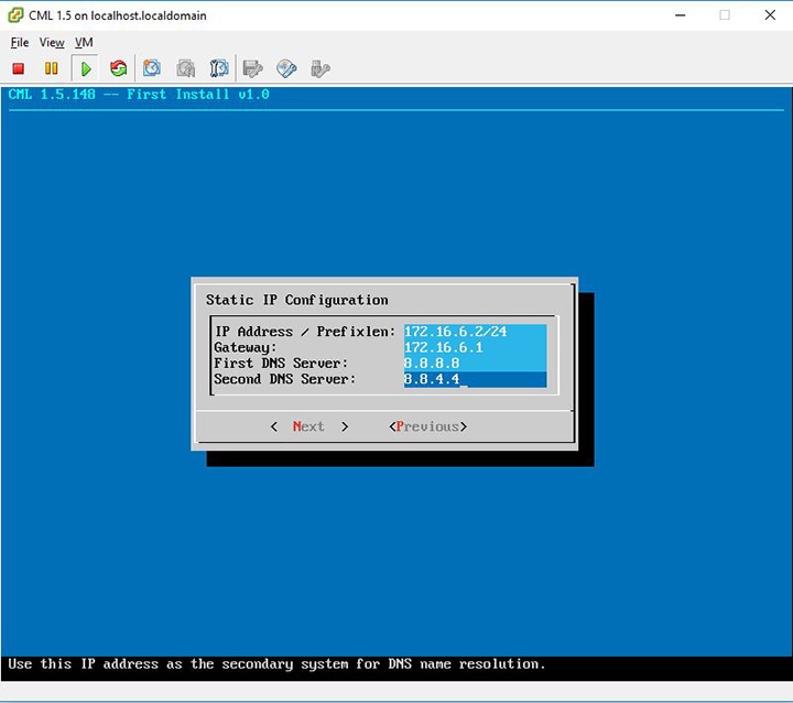
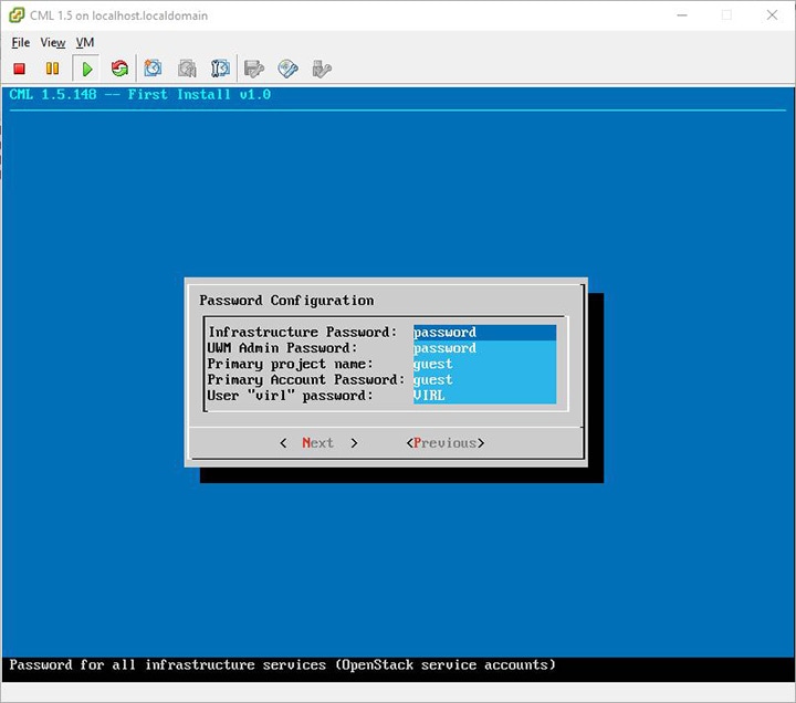
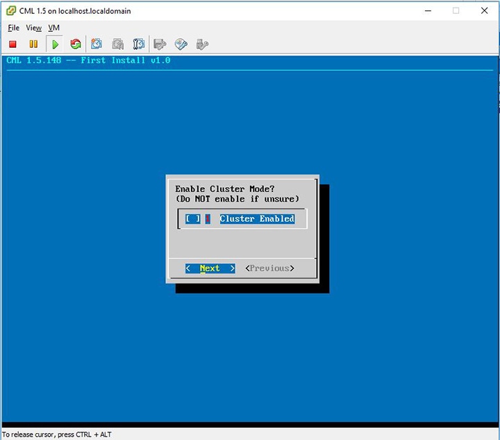
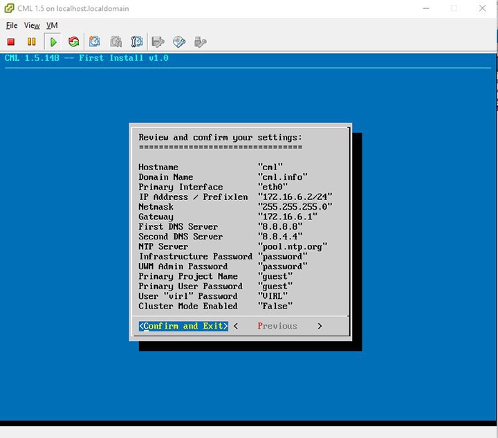
If the Cisco UCS C-Series server is being freshly deployed, there are some preliminary preparations that are necessary to prepare the hardware. These include configuring the server’s dedicated management interface (CIMC); verifying that the necessary Virtualization Technology features are enabled in the BIOS; and preparing the storage for the installation. The following steps are associated with the Cisco UCS C220 M4S platform running Version 2.06(6d) BIOS/CICM firmware. Refer to the applicable documentation if other server types or firmware levels are to be used and adjust the process accordingly.

Prepare the Cisco Integrated Management Controller (CIMC) Interface

If not previously used, the server's Cisco Integrated Management Controller (CIMC) must be provisioned as follows:

Procedure


Step 1

Connect a USB keyboard and VGA monitor to the server using one of the following methods:

  1. Using the corresponding connectors on the rear panel.

  2. Using the optional KVM cable (Cisco PID N20-BKVM) to the connector on the front panel.

Step 2

Power on the server via the front panel Power button. The server will undergo its Power-On Self Testing (POST) cycles and hardware initializations, as shown.

Figure 1. Power-On Self Testing Cycles and Hardware Initialization


Step 3

When the POST cycles finish, the server setup menu is presented. Press the <F8> key to enter the Cisco IMC Configuration Utility.

Figure 2. Cisco Setup Menu


Step 4

In the Cisco IMC Configuration Utility, enter the networking details to be assigned to the server's dedicated management port. Use the <Up>/<Down> arrow keys to select parameter, and the <Space> key to toggle on/off.

Figure 3. CIMC Configuration Utility


Typical settings are to set NIC mode to Dedicated and to set NIC redundancy to None. Configure IP addressing and VLAN details per site requirements. Press the <F10> key to save the entries and continue the boot process.

Step 5

If not already done, connect the server's dedicated management port to its adjacent access switch. From a Windows (or Apple) client machine, verify network connectivity to the CIMC host interface.


Access the CIMC Interface

With the CIMC interface configured, it is accessed to complete the machine preparation and to facilitate the software installation.

Procedure


Step 1

Using a Windows (or Apple) workstation, initiate a browser session to the CIMC interface using the address provisioned in the previous steps.

Step 2

In the CIMC login page, enter the username and password for the CIMC interface. The default credentials are admin and password. If the password was changed during server setup, use the currently configured password.

Figure 4. CIMC Interface


Step 3

At this point, BIOS CPU Virtualization Technology (VTx) features may be verified, as follows:

  1. Choose Server > BIOIS.

  2. Choose Actions > Configure BIOS

  3. In the pop up window, select the Advanced tab. For Cisco UCS platforms, the VT extensions should be enabled by default, as shown.

    Figure 5. Verify BIOS Configuration


Step 4

Verify the CIMC network configuration is set for best performance. Select Network under the Admin tab. Enable the management port’s Auto Negotiation. By default, the port may be set for 100mbps/Half Duplex; this will severely impair the ISO file transfer process.

Figure 6. Verify Network Configuration


Step 5

If this is a new machine, the storage sub-system may need to be set up and initialized. As there are a wide variety of options with respect to storage, the exact deployment details will depend on the employed storage components utilized. For specific installation procedures, review product documentation and feature descriptions associated with actual storage options. The following illustrates the most common Direct Attached Storage (DAS) using the integral MRAID module. To configure the MRAID controller:

  1. A pre-boot utility may be invoked by entering <Ctrl-R> during the boot-up process. This will directly access the on-board ROM-based configuration utility.

  2. Within the CIMC interface, select the Storage tab to display the Modular Raid Controller. Under the Controller Info tab, click the Create Virtual Drive from Unused Physical Drives option. In the popup window, choose the desired RAID level from the drop-down menu. In the list of Physical Drives, select the participating member(s) by clicking the Select box, as shown.

Figure 7. Configure the MRAID Controller


Depending on the selected RAID level, this can be one or more selections. When the array members have been selected, click >> to allocate them to the Drive Group. With the Drive Group membership defined, click Create Virtual Drive. Clicking the Virtual Drive Info tab displays a report of the Virtual Drives controlled by the MRAID module and their status.
Note 
In this example the Virtual Drive #0 is the selected boot drive, as shown.
Figure 8. Create a Virtual Drive


Map the Cisco Modeling Labs ISO Disk Image

To map the Cisco Modeling Labs ISO disk image, complete the following steps:

Procedure


Step 1

With the Cisco UCS server properly prepared for the Cisco Modeling Labs installation, the ISO installation media must be virtually (remote) mounted to the target server. In the CIMC interface, open a KVM Console to the server by clicking the associated icon in the tool bar or the within the Actions pane.

Figure 9. KVM Console


Note 
If using a Java-enabled browser, a series of PopUp windows will appear; acknowledge each and the KVM Console window will open. If the browser is not java-enabled (e.g. Chrome), manually open the downloaded viewer.jnlp file with the javaws.exe application and acknowledge the series of PopUps.
Step 2

In the KVM Console window, click Virtual Media from the menu bar. From the drop-down, choose the Activate Virtual Devices. Acknowledge the Unencrypted Virtual Media Session warning and click Apply, as shown.

Figure 10. Activate Virtual Devices


Step 3

In the KVM Console window, click Macros from menu banner. In the drop-down list, choose Static Macros > Ctrl-Alt-Del to trigger a server reboot.

Step 4

During the reboot cycle, when the server setup screen is displayed, press the <F6> key. Choose the Cisco vKVM-Mapped vDVD option for the boot device. When complete, the server will boot the ISO disk image file.


Run the Cisco Modeling Labs Installer

The system boots from the previously mapped Virtual Media CD/DVD Device. On initial startup, the system reports the status of the eth0 interface. This can be set for the assigned static IP address later. After a small delay, the Ubuntu (GRUB) boot loader menu is displayed.
Figure 11. CML Installer Window


Complete the following steps to install Cisco Modeling Labs.

Procedure


Step 1

Select the CML Live Installer option and press Enter to continue booting from the mounted ISO image file. Upon completion of the startup cycle, the Ubuntu Login screen is presented.

Figure 12. Ubuntu Login Screen


Step 2

Login to Cisco Modeling Labs using the virl/VIRL credentials.

Figure 13. Ubuntu Desktop


Step 3

On the desktop, double-click Install Cisco Modeling Labs to begin the installation.

Figure 14. Installation Started


Step 4

After verifying the installation configuration, the Installation Type page is presented. Set the Installation type to Erase disk and Install Ubuntu. We recommend that you enable the Use LVM with the new Ubuntu installation option, to setup Logical Volume Management. Click Install Now.

Figure 15. Installation Type Page


Step 5

When the disk formatting warning is presented, click the Continue button to initiate the software installation process. The bar graph indicates the software transfer process.

Figure 16. Copying Files


Step 6

When complete, you are prompted to remove the install installation medium. Using the virtual console menus, deselect the ISO mapping and returning to the console session. Press Enter to trigger a system reboot using the freshly installed system.

Figure 17. Newly Installed System


Once the system has rebooted to the local storage, return to the virtual KVM Console via the UCS CIMC interface. Cisco Modeling Labs will go through the initial install, and then a welcome screen will be presented.


Start the Cisco Modeling Labs Server for the First Time

On initial startup of Cisco Modeling Labs, a virtual console session is started to ascertain the assigned IP address, or to set the static addressing details to the Ethernet0 interface. Complete the following steps to start the Cisco Modeling Labs server for the first time.

Figure 18. Installation Tool Welcome


Procedure


Step 1

Upon first boot, you will be asked a few questions. The deployment assistant will do the rest.

Step 2

Configure the host by entering the Hostname, Domain Name, and NTP Server.

Note 
The CML Host Name cannot be changed in the future.
Figure 19. Hostname Configuration


The following sections outline the steps involved for assigning static IP addressing or DHCP deployment. Click the applicable section as required.

Static IP Address Assignment

From the ESXi virtual machine console, assign the static IP address as follows:

Procedure

Step 1

On the interface configuration screen, select Primary Interface eth0.

Figure 20. Interface Configuration Screen


Step 2

Select the Static IP and then Next.

Figure 21. Static IP Assignment


Step 3

Assign the IP in CIDR format.

Figure 22. Static IP Configuration


Step 4

Configure the password for the infrastructure.

Figure 23. Password Configuration


Step 5

Select the cluster setting.

Figure 24. Cluster Enable Configuration


Complete the initial settings.

Figure 25. Completing the Initial Setting


Step 6

Once the virtual machine completes the reboot cycle, the login screen provides information on how to establish a browser session to the Cisco Modeling Labs server’s management interface, using the static address http://<static_ip_address> added to the eth0 interface.

Figure 26. CML Login Screen


The CML Server main menu is displayed.

Figure 27. CML Server Main Menu


Step 7

Click the User Workspace Management interface link. Login with the default credentials (username= uwmadmin, password=password). The User Workspace Management Overview page is displayed.

Figure 28. User Workspace Management Overview


Step 8

From the options on the left, expand the CML Server option and select System Configuration.

Update the system configuration as required.
Figure 29. System Configuration Controls


Table 1. System Configuration Parameters

Parameter

Default

Description

NTP Server

pool.ntp.org

An NTP resource is required. If behind a firewall/proxy, this parameter should point to an NTP server that is reachable by this device.

HTTPS Proxy

blank

The proxy server to use when downloading system installation packages, VMs, or Docker images from public repositories and when accessing remote git repositories. This value must be configured if this machine cannot reach the public Internet directly. Only an appropriate firewall and HTTPS proxy setup, which is external to this server, can enforce restrictions on the content downloaded from the public Internet by logged-in users. Replace with the URL of the Internet Access Proxy, in the format "http://<proxy IP or name>:<port number>/".

Exempt Locations from HTTPS Proxy

blank

List of addresses or names that are reachable from this server without using the configured HTTPS proxy, such as servers on the local intranet. Use commas to separate the host names, domain names, and IP addresses.

HTTPS Proxy Username

blank

If the configured HTTPS proxy requires authentication, specify the username.

HTTPS Proxy Password

blank

If the configured HTTPS proxy requires authentication, specify the password.

Allow Insecure Docker Registries

blank

Allow Docker image downloads from local and remote repositories, which are not configured with an SSL certificate.

First DNS Server

8.8.8.8

Enter the primary DNS server IP address.

Second DNS Server

8.8.4.4

Enter the secondary DNS server IP address. Ensure you do not set the same address as you set for the primary DNS server IP address.

Step 9

Click Hardware to manage the memory.

Table 2. Hardware Configuration Parameters

Parameter

Default

Description

Store Simulation VM Drives in RAM

No

Each simulation VM node had at least one simulated hard drive, initially a shared copy of that node&#39;s image file, with changes made by individual nodes written to that node&#39;s separate file. Storing all these files in RAM significantly speeds up nodes&#39; performance, especially on startup. Enabling this option is recommended only on systems with plenty of memory to spare, especially if very slow startup times are observed (nodes become ACTIVE but remain inoperational-unreachable, or not getting to CLI prompts).

Enable (U)KSM

No

(Ultra) Kernel Samepage Merging [(U)KSM] is a Linux feature that allows multiple VM nodes to share the same memory pages for data that that they hold in common.

Enabling (U)KSM comes at a cost of more CPU time used by the host system at the expense of the VM nodes in the network simulation. Enabling this option may allow small, memory-constrained systems to run a few more VM nodes of the same kind (e.g. IOSv, same image version), even if they do use the memory allotted to them.

It is not recommended to enable this option on larger installations that have the capacity to run dozens of nodes without enabling (U)KSM.

Step 10

Click Networks to configure the other interfaces for external communications.

Table 3. Networks Configuration Parameters

Parameter

Default

Description

Flat Network Port

Eth1

Enter the Flat network port.

Flat Network Address

172.16.1.254/24

Enter the Flat network address.

Flat Network Address/Mask

172.16.1.0/24

Enter the Flat network address/mask.

Flat Network Netmask

255.255.255.0

Enter the Flat network netmask.

Flat Network Gateway IP Address

172.16.1.1

Enter the Flat network gateway IP address.

Flat Address Pool Start Address

172.16.1.50

Enter the Flat address pool start address.

Flat Address Pool End Address

172.16.1.253

Enter the Flat address pool end address.

Flat Primary DNS server IP address

8.8.8.8

Enter the Flat primary DNS server IP address.

Flat Secondary DNS server IP address

8.8.4.4

Enter the Flat secondary DNS server IP address. Ensure you do not set the same address as you set for the primary DNS server IP address.

2nd Flat Network Enabled

Unchecked

Use this option if a second Flat network, Flat1, is to be enabled.

2nd Flat Network Port

Eth2

Enter the name of the host's physical port used for the L2 Flat network, Flat1.

2nd Flat Network Address

172.16.2.254/24

Enter the IP address for the second Flat network, Flat1.

2nd Flat Network Address/Mask

172.16.2.0/24

Enter the Flat network address/mask for Flat1.

2nd Flat Network Netmask

255.255.255.0

Enter the Flat network netmask for Flat1.

2nd Flat Network Gateway IP Address

172.16.2.1

Enter the Flat network gateway IP address for Flat1.

2nd Flat Address Pool Start Address

172.16.2.50

Enter the Flat address pool start address for Flat1.

2nd Flat Address Pool End Address

172.16.2.253

Enter the Flat address pool end address for Flat1.

2nd Flat Primary DNS server IP address

8.8.8.8

Enter the Flat primary DNS server IP address for Flat1.

2nd Flat Secondary DNS server IP address

8.8.4.4

Enter the Flat secondary DNS server IP address for Flat1. Ensure you do not set the same address as you set for the primary DNS server IP address.

Snat Network Port

Eth3

Enter the name of the host's physical port used for L3 Snat network, ext-net.

Snat Network Address

172.16.3.254/24

Enter the IP address for the CML host in the L3 Snat network.

Snat Network Address/Mask

172.16.3.0/24

Enter the Snat network address/mask.

Snat Network Netmask

255.255.255.0

Enter the Snat network netmask.

Snat Network Gateway IP Address

72.16.3.1

Enter the Snat network gateway IP address.

Snat Address Pool Start Address

172.16.3.50

Enter the Snat address pool start address.

Snat Address Pool End Address

172.16.3.253

Enter the Snat address pool end address.

Snat Primary DNS server IP address

8.8.8.8

Enter the Snat primary DNS server IP address.

Snat Secondary DNS server IP address

8.8.4.4

Enter the Snat secondary DNS server IP address. Ensure you do not set the same address as you set for the primary DNS server IP address.

Step 11

Click Service Ports to configure the port numbers for VIRL services.

Table 4. Services Configuration Parameters

Parameter

Default

Description

Apache Server Port

80

Enter the number of the Apache server port.

Start Host-granted TCP Port

10000

Host grants TCP ports to the simulations starting from this value.

End Host-granted TCP Port

17000

Host grants TCP ports to the simulations starting ending with this value.

First VM Serial Console TCP Port

17000

Simulated VMs with serial consoles use TCP ports starting from this value.

Last VM Serial Console TCP Port

18000

Simulated VMs with serial consoles use TCP ports ending with this value.

VIRL Web Services Port

19399

Enter the TCP port number for the simulation engine services.

UWM Port

19400

Enter the TCP port number for the User Workspace Management interface.

AutoNetkit Webserver Port

19401

Enter the TCP port number for the configuration engine preview interface.

Live Visualization Webserver Port

19402

Enter the TCP port number for the Live Visualization interface.

UWM Web-SSH Port

19403

Enter the TCP port number for the User Workspace Management SSH web interface.

Nova Websocket Serial Port

19406

Enter the TCP port number for the websocket-based serial console connections.

Disable Serial Timeout

Unchecked

Disable timeout of serial consoles after 15 minutes of inactivity.

Nova Websocket VNC Port

19407

Enter the TCP port number for the websocket-based VNC console connections.

Docker Registry Port

19397

Enter the port number for the docker registry.

Step 12

Click Users to configure the other infrastructure passwords.

Table 5. Infrastructure Configuration Parameters

Parameter

Default

Description

Enable Primary Project

Yes

Create a main project used for running simulations.

Primary Project Name

guest

Name for the primary project. Avoid using the reserved values: admin, cinder, glance, keystone, neutron, nova, and uwmadmin.

Primary Account Password

guest

Password for primary project user account.

UWM Admin Password

password

Password used by the UWM admin user for UWM administration.

Restrict System Configuration and Upgrades to System Admin

Yes

If disabled, any admin user may make changes and operate this system configuration.

Users Allowed Resource Management

Any active user

Select which users may manage node resources, such as Images and LXC Templates. Also may further restrict admin management of Flavors and Subtypes.

Infrastructure Password

password

Password used for all infrastructure services (OpenStack service accounts).

Step 13

Click Simulation Details and select Serial Port inactivity timeout, which is No by default. This is required because simulated VM serial console (telnet) connections can normally be interrupted by the client. An inactivity timeout of 15 minutes protects each serial connection against hogging by possibly unreachable clients.

Step 14

With all configuration options set, click Apply Changes. At this point, the system will ask you to please enable maintenance mode first as shown.

Figure 30. Enable Maintenance Mode


Click Enable Maintenance Mode as requested.
A Maintenance Mode dialog box is displayed.
Figure 31. Maintenance Mode Dialog Box


Click Enable. The system is now in maintenance mode.

Step 15

Click Apply Changes as shown.

Figure 32. Apply Changes Made


Note 
You must click Apply Changes at this point in order for your configuration updates to take effect.
Under the Jobs in Progress panel, you can see the progress of the rehost operations as the page refreshes periodically, as shown.
Figure 33. Jobs in Progress


Step 16

When completed, click Reboot to reboot the system.

The Reboot System dialog box is displayed.
Figure 34. Reboot System Dialog Box


Step 17

Click Reboot to reboot the system.

The System Configuration page is displayed.
Figure 35. System Configuration Page


Step 18

Click Disable Maintenance Mode.

A Maintenance Mode dialog box is displayed.
Figure 36. Maintenance Mode Dialog Box


Step 19

Click Disable. The system is no longer in maintenance mode.

Your configuration is complete.
Figure 37. System Configuration Completed


Step 20

Click OK on the System Configuration page to return to the System Configuration Controls page.


DHCP Deployment

On initial startup of Cisco Modeling Labs, a virtual console session is started to ascertain the assigned IP address, or to set the static addressing details to the Ethernet0 interface. Complete the following steps to start the Cisco Modeling Labs server for the first time.

In the Console window, you can see the virtual machine starting up.
Figure 38. Virtual Machine Starting Up


Procedure

From the ESXi virtual machine console, deploy DHCP as follows:

  1. Select Use DHCP on Primary Interface.

  2. Select DHCP and click Next.

    Figure 39. DHCP IP Assignment


To finish the setup, perform 3 to Step 20 as detailed in the section Static IP Address Assignment.


Verify that Required Interfaces are Present

The Cisco Modeling Labs bare-metal install requires 5 network interfaces, named eth0, eth1, eth2, eth3, and eth4. The presence of these interfaces should be verified at this point. Following install options 1 (live) or 2 (install), the Cisco Modeling Labs server is re-booted from the local disk. On completion of the reboot, log back into the console and open an xterm session.

From a console xterm session, running the command ifconfig | grep eth should return a list of 5 interfaces named eth0 though eth4.
Figure 40. List of Five Interfaces


If a PCI or LOM-based Ethernet controller is confirmed as installed, but the ifconfig command returns a listing of only 2 interfaces, it is possible that the server detected the interfaces using a different name (e.g. em2, em3, and so on.
Figure 41. List of Two Interfaces Only


This naming discrepancy can be verified using the ip link show command. In this example, the PCIe-based interfaces are recognized as em1 – em4 as highlighted.
Figure 42. Use the ip link show Command


To reset the interface names to the format expected by the Cisco Modeling Labs installer, complete the following steps:
  1. Edit the /etc/default/grub file: sudo nano /etc/default/grub

  2. Search for the follow two lines:
    
    GRUB_CMDLINE_LINUX_DEFAULT=””
    GRUB_CMDLINE_LINUX=””
    
  3. Edit the lines as follows:
    
    GRUB_CMDLINE_LINUX_DEFAULT=”biosdevname=0”
    GRUB_CMDLINE_LINUX=”biosdevname=0”
    Figure 43. Updated File


  4. Save the /etc/default/grub file and exit using [Ctrl-X; Yes; Enter]

  5. Complete the update using the command: sudo update-grub

  6. Reboot the server to effect the changes: sudo reboot now

  7. On completion of the system restart, verify that the required number of Ethernet interfaces conforming to the ethN naming format are now available on the operating system. If not, this must be diagnosed and resolved before proceeding, or the interface-constrained installation steps performed.

Determine License Key Requirements

Returning to the User Workplace Management interface shows the server’s current licensing status; the red banner indicates that there is no product licensing in place.

To license the Cisco Modeling Labs server, complete the following steps:

Procedure


Step 1

In the left pane, click Licenses .

The Licenses page is displayed.
Figure 44. Licenses Page


Step 2

In the Licenses page, click Register Licenses .

Step 3

Record the Host Name and Mac Address for license key registration.

Figure 45. Information for License Key Registration


Use this information when completing the Register Claim Certificates instructions in the eDelivery Order Notification email to request your license key for use with the Cisco Modeling Labs server.

Two types of licenses are available, as shown in the following table.
Table 6. License Types
License Type Description
Base Subscription 15-node capacity for initial deployment.
Capacity Subscription 10-node, 50-node, and 100-node bundles available.
Note 
You can have any number or type of licenses. Licenses are determined by the node capacity you want to deploy.

You will receive your license key as an attachment via an email.

Step 4

Open the attachment in a text editor and copy all of the contents.

Step 5

Return to the Register Licenses page and paste the details into the Licenses text area.

Figure 46. License Key Details


Step 6

Click Register to register the license key.

Note 

We recommend that you add the Base Subscription license first.

Under Licenses, you will see the license that is added, the number of nodes permissible, and an expiry date for the license.
Figure 47. Licenses Applied


Step 7

Repeat Steps 4 – 6 for each license file received from the registration process. Verify that the Licenses page correctly reports the applied node count and expiration dates.

Step 8

Click Log Out to exit the User Workspace Management interface.