Cisco Catalyst Center Third-Generation Appliance Installation Guide, Release 3.1.x
Bias-Free Language
The documentation set for this product strives to use bias-free language. For the purposes of this documentation set, bias-free is defined as language that does not imply discrimination based on age, disability, gender, racial identity, ethnic identity, sexual orientation, socioeconomic status, and intersectionality. Exceptions may be present in the documentation due to language that is hardcoded in the user interfaces of the product software, language used based on RFP documentation, or language that is used by a referenced third-party product. Learn more about how Cisco is using Inclusive Language.
You can deploy the appliance in your network in one of these two modes:
Standalone: As a single node offering all the functions. This option is usually preferred for initial or test deployments,
and in smaller network environments. If you select Standalone mode for your initial deployment, you can add more appliances
later to form a cluster. When configuring the standalone host, ensure that you set it up as the first, or primary, node in
the cluster.
Cluster: As a node that belongs to a three-node cluster. In this mode, all the services and data are shared among the hosts.
This is the preferred option for large deployments. If you select Cluster mode for your initial deployment, be sure to finish
configuring the primary node before configuring the secondary nodes.
You cannot restore a backup file from an appliance that uses IPv4 to an appliance that uses IPv6, or vice versa.
If your appliance uses IPv6 addressing, see the "IPv6 Limitations" section in the Release Notes for Cisco Catalyst Center for a description of the features that are not supported.
Password considerations
Refer to these topics for a description of the changes made to Catalyst Center's implementation of passwords.
Can only be enabled when you configure a Catalyst Center appliance using the Maglev Configuration wizard.
Cannot be enabled using any of the browser-based configuration wizards.
Cannot be disabled without reimaging the appliance.
Disaster recovery is not supported by Catalyst Center deployments that have VLAN mode enabled.
Configure the primary node using the Maglev wizard
Do the steps in this procedure to configure the first installed appliance as the primary node. You must always configure the
first appliance as the primary node, whether it will operate standalone or as part of a cluster.
If you are configuring the installed appliance as a secondary node for an existing cluster that already has a primary node,
follow the steps described in Configure a secondary node using the Maglev wizard instead.
Important
Verify that all of the IP addresses you enter while completing this procedure are valid addresses with valid netmasks. Also
verify that the addresses and their corresponding subnets do not overlap. Service communication issues can result if they
do.
Before configuring the appliances in a three-node cluster, log out of those appliances. If you remain logged in, the Quick
Start workflow—which you use to discover network devices and enable telemetry—does not start after you configure your cluster’s
appliances and log in to Catalyst Center for the first time.
Checked that the ports of the primary node appliance, and the switches they use, are properly configured, as described in
Execute preconfiguration tasks.
Confirmed that you are using a compatible browser. For a list of compatible browsers, see the Release Notes document for the release of Catalyst Center you are installing.
Enabled ICMP on the firewall between Catalyst Center and both the default gateway and the DNS server you specify in this procedure. The Maglev Configuration wizard uses ping
to verify the gateway and DNS server you specify.
Caution
If ICMP is not enabled and a firewall is in place, the ping may be blocked, which will prevent you from completing the wizard.
After you log in, the appliance displays the Cisco Integrated Management Controller Chassis Summary window with a hyperlinked menu at the top.
Step 2
From the hyperlinked menu, select Launch KVM and then select HTML-based KVM.
The KVM console opens in a separate window or tab automatically. Use it to monitor the progress of the configuration and respond
to the Maglev Configuration wizard prompts.
Step 3
With the KVM displayed, reboot the appliance by making one of these selections:
In the main Cisco IMC GUI browser window: Choose Host Power > Power Cycle, and switch to the KVM console to continue.
In the KVM console: Choose Power > Power Cycle System (cold boot).
If you are asked to confirm your choice to reboot the appliance, click OK.
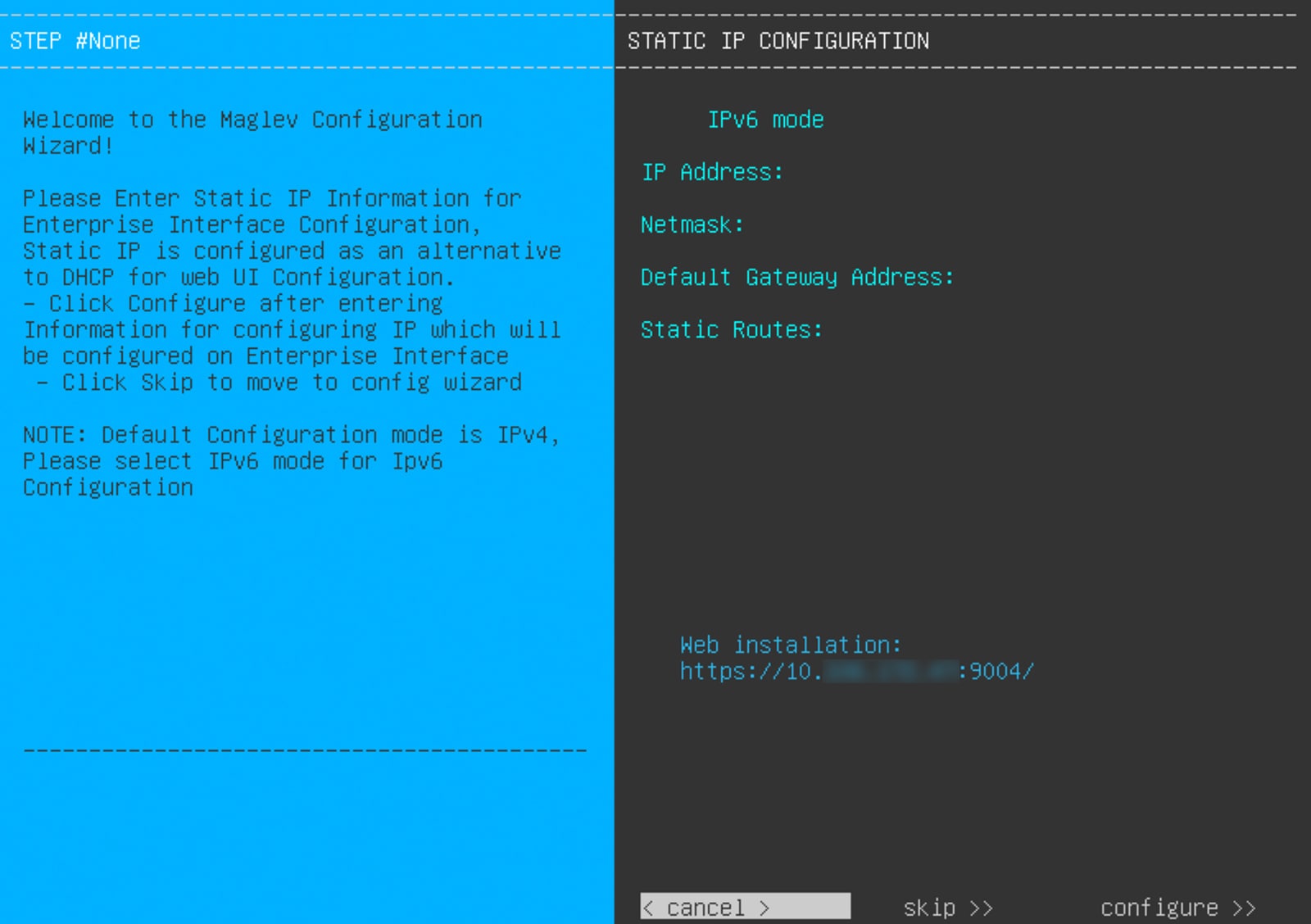
After displaying reboot messages, the KVM console displays the Static IP Configuration screen.
Step 4
Click Skip.
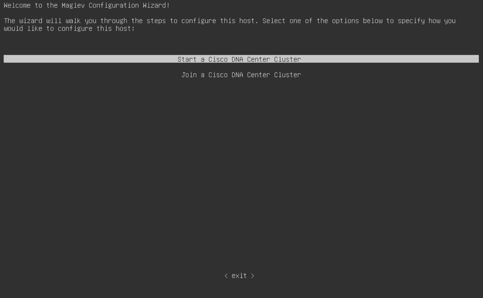
The KVM console displays the Maglev Configuration wizard welcome screen.
Note
Only users that want to configure their appliance using one of the browser-based wizards without using the IP address, subnet
mask, and default gateway assigned to the appliance's Enterprise interface by a DHCP server need to complete this screen.
Step 5
Click Start a Catalyst Center Cluster to begin configuring the primary node.
The screen updates.
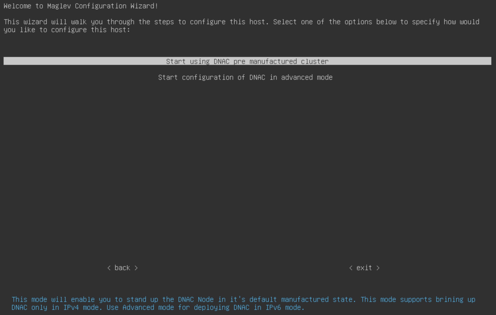
Step 6
Select one of these options:
Start using DNAC pre manufactured cluster: Select this option to configure an appliance with its default settings in place:
You will not be able to change any of these settings, so select this option only if you want to use them.
Important
This option is only available if you are configuring a new Catalyst Center appliance. If you are reimaging your appliance, the wizard continues with the Start configuration of DNAC in advanced mode option selected.
Start configuration of DNAC in advanced mode: Select this option to configure an appliance that doesn't use one or more of the default settings listed in the previous
bullet. Also select this option if you want to use IPv6 addressing on your appliance.
The screen updates.
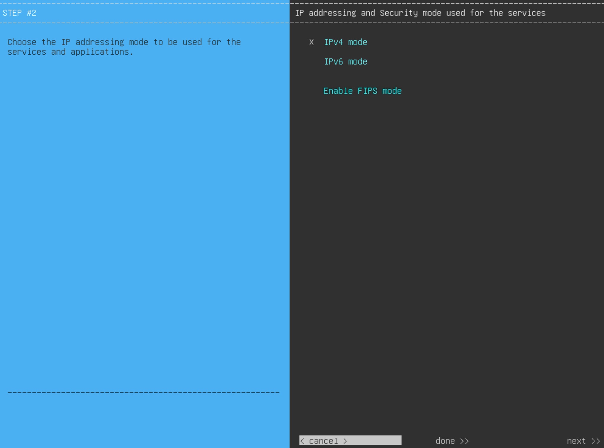
Step 7
Do these steps, then click next>> to continue:
Specify whether the applications and services running on your Catalyst Center appliance will use IPv4 or IPv6 addressing.
(Optional) Check the Enable FIPS Mode check box to enable FIPS mode on your Catalyst Center appliance.
See FIPS mode support for things to keep in mind when enabling FIPS mode on an appliance.
Important
In the next wizard screen, you can enable the VLAN mode feature, which creates a single bonded interface that connects to your network using both the primary and secondary instance
of your appliance's Enterprise interface. This feature is not commonly used. Enable it only if your Catalyst Center deployment requires it.
If this is the case, complete the next step.
Otherwise, click next>> in the next wizard screen without making any selections. You can enable the NIC bonding functionality that was described
previously in this guide in the wizard's Enterprise and Intracluster interface configuration screens.
Step 8
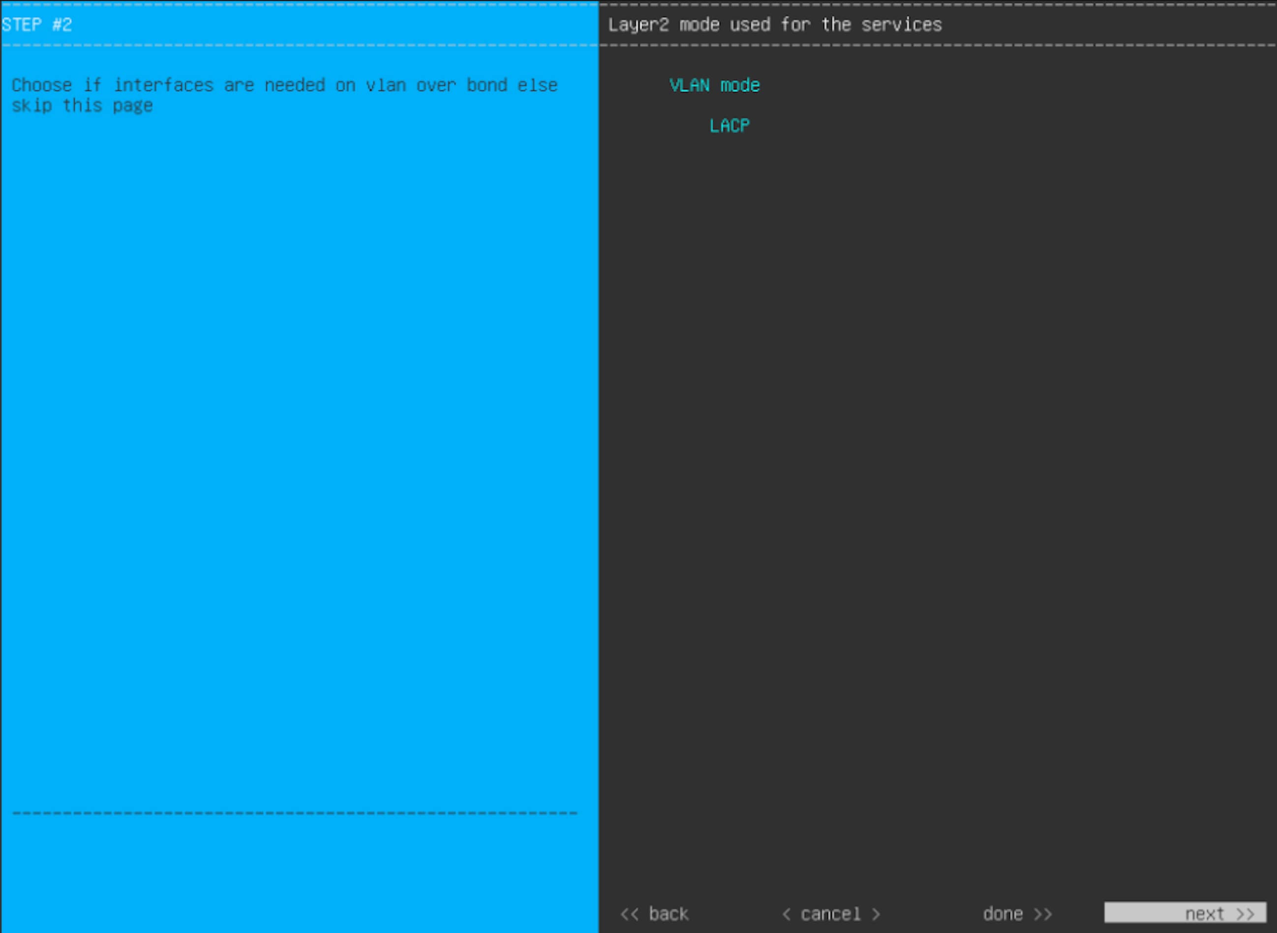
(Optional) Follow the onscreen instructions to enable Layer 2 port channel mode (with VLAN tagging) for the appliance. After
making your selections, click next>> to continue.
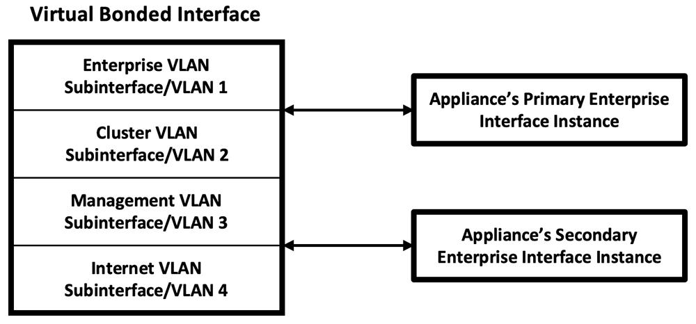
Select the VLAN mode option to enable dot1q/VLAN trunking and convert your appliance's Enterprise, Cluster, Management, and Internet interfaces
into VLAN subinterfaces that reside on the bonded interface (as illustrated in this figure). By default, this interface operates
in Active-Backup mode (which enables HA).
If you want this interface to operate in LACP mode instead (which enables load balancing and higher bandwidth), you must also
select the LACP option.
When you enter the settings for your appliance's Enterprise and Cluster interfaces, ensure that you enter a unique VLAN ID
in the VLAN ID of Interface field for the subinterfaces you want to configure on the virtual bonded interface.
Important
Even though one physical appliance interface (the Enterprise interface) is connected, you can configure all of the subinterfaces
that reside on the virtual bonded interface.
The wizard discovers all of the ports on the appliance and presents them to you one by one, in separate screens, in this order:
(Optional) 1 Gbps/10 Gbps Internet port—network adapter #4
If the wizard fails to display either or both of the Enterprise and Cluster ports during the course of configuration, it might
indicate that these ports are nonfunctional or disabled. These two ports are required for Catalyst Center functionality. If you discover that they are nonfunctional, select cancel to exit the configuration wizard immediately. Be sure that you have completed all of the steps provided in Execute preconfiguration tasks before resuming the configuration or contacting the Cisco Technical Assistance Center.
Step 9
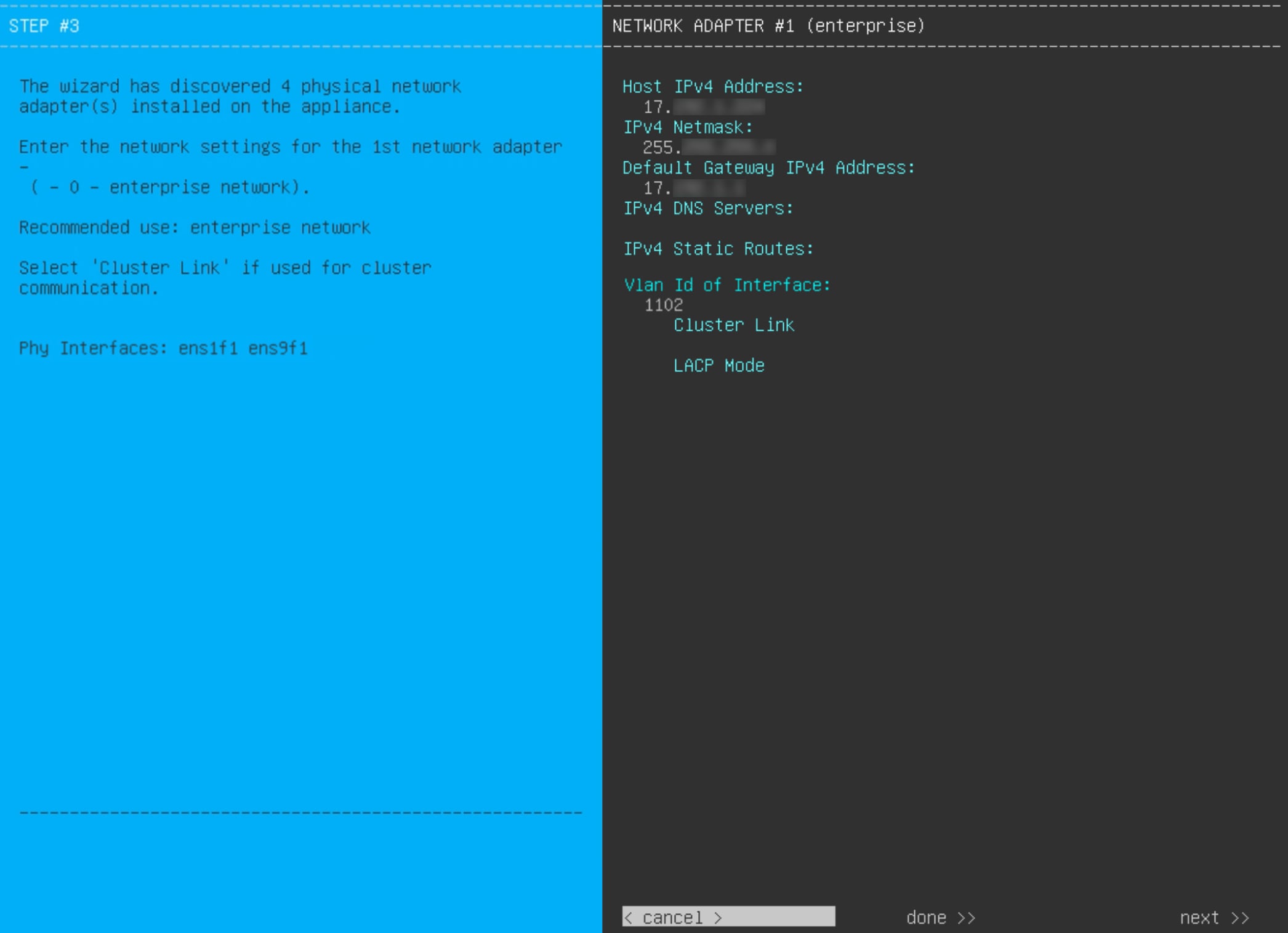
The wizard first presents the 10 Gbps Enterprise port as NETWORK ADAPTER #1. As explained in Interface cable connections, this is a required port used to link the appliance to the enterprise network. Apply the host IP address, netmask, and other
values that are appropriate for this purpose (see Required IP addresses and subnets and Required configuration information for the values to enter).
This table lists the configuration values for NETWORK ADAPTER #1 to enter.
Table 1. Primary node entries for network adapter #1: 10 Gbps Enterprise port
Host IPv4/IPv6 Address field
Enter the IP address for the Enterprise port. This is required.
IPv4 Netmask/IPv6 Prefix Length field
Do one of these tasks:
If you selected IPv4 addressing, enter the netmask for the port's IP address. This is required.
If you selected IPv6 addressing, enter the prefix length (in bits). Valid values range from 10 through 127.
Default Gateway IPv4/IPv6 Address field
Enter a default gateway IP address to use for the port.
Important
Ensure that you enter a default gateway IP address for at least one of your appliance's interfaces. Otherwise, you will not
be able to complete the configuration wizard.
IPv4/IPv6 DNS Servers field
Enter the IP address of the preferred DNS server. If you are entering multiple DNS servers, separate the IP addresses in the
list with spaces.
Important
For each appliance in your cluster, configure a maximum of three DNS servers. Problems can occur if you configure more than
three DNS servers for an appliance.
IPv4/IPv6 Static Routes field
Enter one or more static routes in this format, separated by spaces: <network>/<netmask>/<gateway>. This is usually required on the Catalyst Center Management port only.
VLAN ID of Interface field
Enter the VLAN ID for the bonded interface you enabled in the previous step. If you didn't enable it, this field will not
be displayed.
Cluster Link field
Leave this field blank. It is required on the Cluster port only.
LACP Mode field
Do one of these tasks:
Leave this field blank and the port will operate in Active-Backup mode. This mode provides fault tolerance by aggregating two Ethernet interfaces into a single logical channel. When the interface
that's currently active goes down, the other interface takes its place and becomes active.
Check the check box to enable LACP mode on this port. This mode aggregates two Ethernet interfaces that share the same speed and duplex settings into a single
logical channel. This provides load balancing and higher bandwidth.
For more information about Catalyst Center's implementation of NIC bonding, see NIC bonding overview.
Note
This field is displayed if you didn't select any of the options in the previous step.
After you finish entering the configuration values, click next>> to continue. The wizard validates the values you entered and issues an error message if any are incorrect. If you receive
an error message, check that the value you entered is correct, then reenter it. If needed, click <<back to reenter it.
Step 10
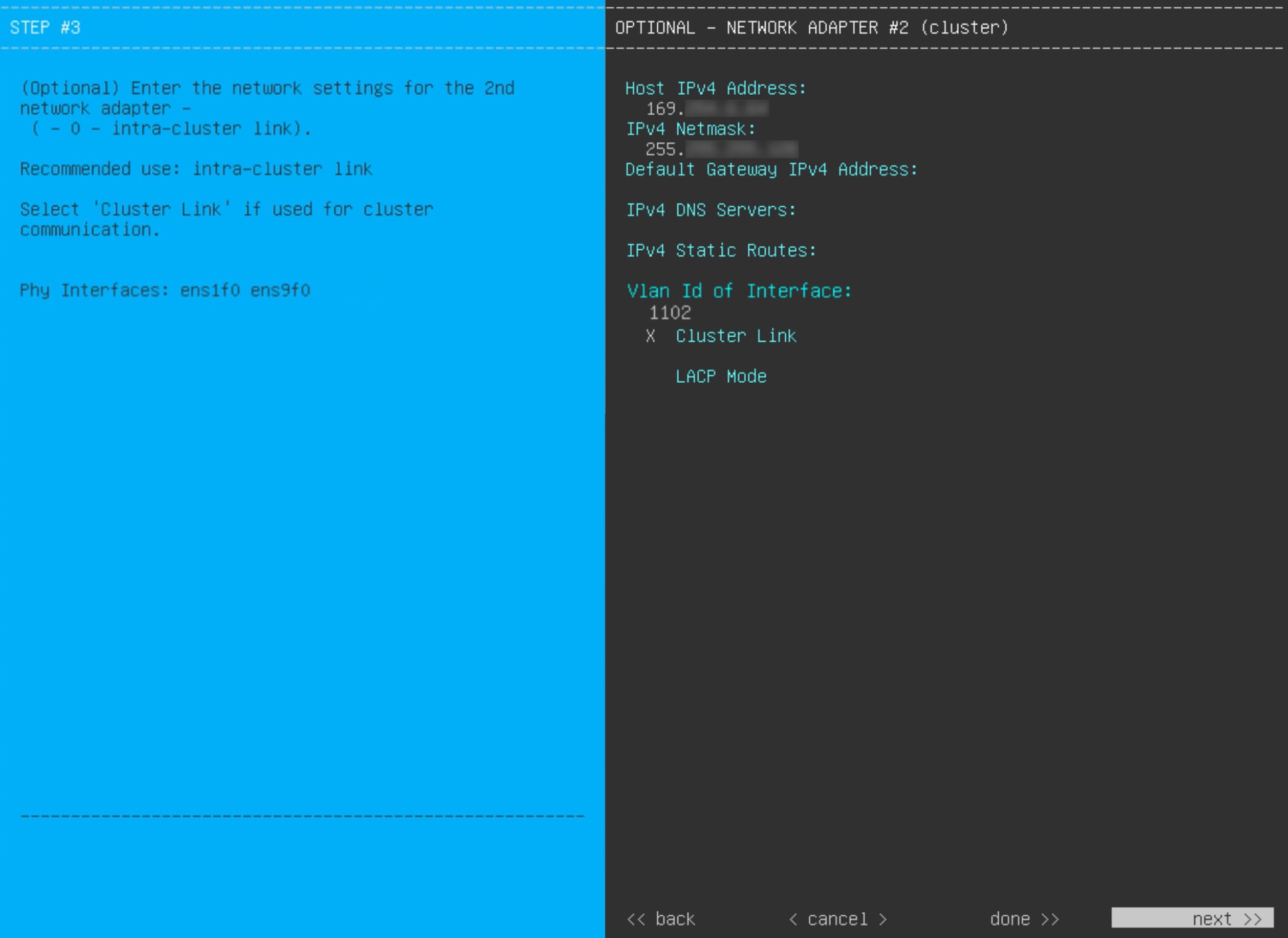
After successful validation of the Enterprise port values you entered, the wizard presents the 10 Gbps Cluster port and presents
it as NETWORK ADAPTER #2. As explained in Interface cable connections, this port is used to link the appliance to the cluster, so apply the host IP address, netmask, and other values that are
appropriate for this purpose (see Required IP addresses and subnets and Required configuration information for the values to enter).
This table lists the configuration values for NETWORK ADAPTER #2 to enter.
Table 2. Primary node entries for network adapter #2: 10 Gbps Cluster port
Host IPv4/IPv6 address field
Enter the IP address for the Cluster port. This is required. You cannot change the address of the Cluster port later.
Note
If you selected the Start using DNAC pre manufactured cluster option previously, 169.254.6.66 will already be set in this field and you will not be able to enter a different address.
IPv4 Netmask/IPv6 Prefix Length field
Do one of these tasks:
If you selected IPv4 addressing, enter the netmask for the port's IP address. This is required.
Note
If you selected the Start using DNAC pre manufactured cluster option previously, 255.255.255.128 will already be set in this field and you will not be able to enter a different netmask.
If you selected IPv6 addressing, enter the prefix length (in bits). Valid values range from 10 through 127.
Default Gateway IPv4/IPv6 address field
Enter a default gateway IP address to use for the port.
Important
Ensure that you enter a default gateway IP address for at least one of your appliance's interfaces. Otherwise, you will not
be able to complete the configuration wizard.
IPv4/IPv6 DNS Servers field
Enter the IP address of the preferred DNS server. If you are entering multiple DNS servers, separate the IP addresses in the
list with spaces.
Important
For each appliance in your cluster, configure a maximum of three DNS servers. Problems can occur if you configure more than
three DNS servers for an appliance.
IPv4/IPv6 Static Routes field
Enter one or more static routes in this format, separated by spaces: <network>/<netmask>/<gateway>. This is usually required on the Management port only.
Cluster Link field
Check the check box to set this port as the link to a Catalyst Center cluster. This is required on the Cluster port only.
LACP Mode field
Do one of these tasks:
Leave this field blank and the port will operate in Active-Backup mode. This mode provides fault tolerance by aggregating two Ethernet interfaces into a single logical channel. When the interface
that's currently active goes down, the other interface takes its place and becomes active.
Check the check box to enable LACP mode on this port. This mode aggregates two Ethernet interfaces that share the same speed and duplex settings into a single
logical channel. This provides load balancing and higher bandwidth.
For more information about Catalyst Center's implementation of NIC bonding, see NIC bonding overview.
Note
This field is displayed if you didn't select any of the options in Step 8.
You can only enable LACP mode on your appliance's Intracluster interface during the initial configuration of your appliance.
After you provide the necessary information, click next>> to continue. Correct validation errors, if any, as you did in previous screens. The wizard validates and applies your network
adapter configurations.
Step 11
After successful validation of the Cluster port values you entered, the wizard presents the 1 Gbps/10 Gbps Management port
and presents it as NETWORK ADAPTER #3. As explained in Interface cable connections, this port is used to access the Catalyst Center GUI from your management network. Apply the host IP address, netmask, and other values that are appropriate for this purpose
(see Required IP addresses and subnets and Required configuration information for the values to enter).
This table lists the configuration values for NETWORK ADAPTER #3 to enter.
After you provide the necessary information, click next>> to continue. Correct validation errors, if any, as you did in previous screens. The wizard validates and applies your network
adapter configurations.
Table 3. Primary node entries for network adapter #3: 1 Gbps/10 Gbps Management port
Host IPv4/IPv6 address field
Enter the IP address for the Management Port. This is required only if you are using this port to access the Catalyst Center GUI from your management network; otherwise, you can leave it blank.
IPv4 Netmask/IPv6 Prefix Length field
Do one of these tasks if you entered an IP address:
If you selected IPv4 addressing, enter the netmask for the port's IP address. This is required.
If you selected IPv6 addressing, enter the prefix length (in bits). Valid values range from 10 through 127.
Default Gateway IPv4/IPv6 address field
Enter a default gateway IP address to use for the port.
Important
Ensure that you enter a default gateway IP address for at least one of your appliance's interfaces. Otherwise, you will not
be able to complete the configuration wizard.
IPv4/IPv6 DNS Servers field
Enter the IP address of the preferred DNS server. If you are entering multiple DNS servers, separate the IP addresses in the
list with spaces.
Important
For NTP, ensure port 123 (UDP) is open between Catalyst Center and your NTP server.
For each appliance in your cluster, configure a maximum of three DNS servers. Problems can occur if you configure more than
three DNS servers for an appliance.
IPv4/IPv6 Static Routes field
Enter one or more static routes in this format, separated by spaces: <network>/<netmask>/<gateway>.
Cluster Link field
Leave this field blank. It is required on the Cluster port only.
Step 12
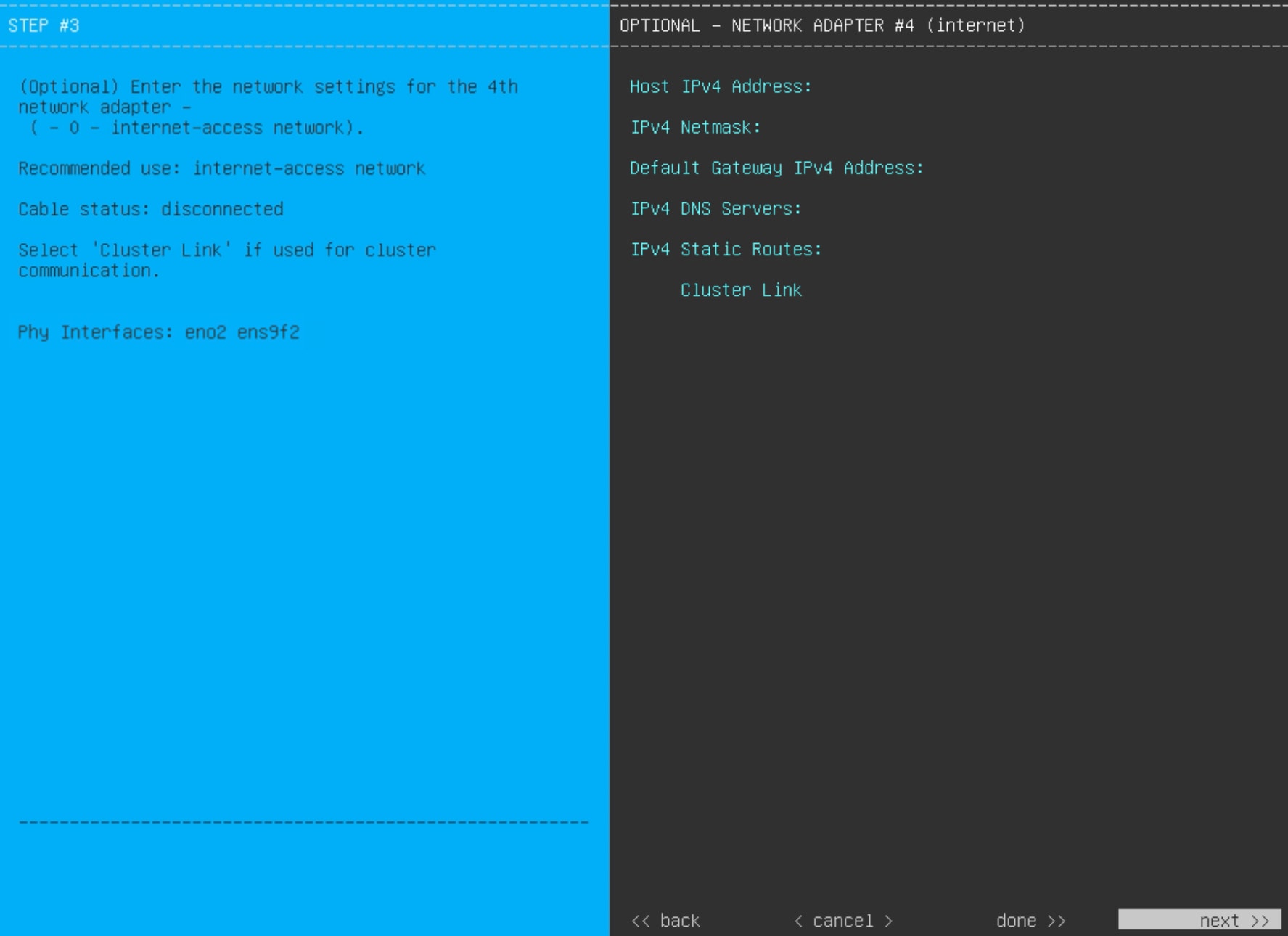
After successful validation of the Management port values you entered, the wizard presents the 1 Gbps/10 Gbps Internet port
as NETWORK ADAPTER #4. As explained in Interface cable connections, this is an optional port used to link the appliance to the Internet when you cannot do so through the 10 Gbps Enterprise
port. Apply the host IP address, netmask, and other values that are appropriate for this purpose (see Required IP addresses and subnets and Required configuration information for the values to enter).
This table lists the configuration values for NETWORK ADAPTER #4 to enter.
Table 4. Primary node entries for network adapter #4: 1 Gbps/10 Gbps Internet port
Host IPv4/IPv6 address field
Enter the IP address for the Internet port. This is required only if you are using the Internet port for internet connection;
otherwise, you can leave it blank.
IPv4 Netmask/IPv6 Prefix Length field
Do one of these tasks if you entered an IP address:
If you selected IPv4 addressing, enter the netmask for the port's IP address. This is required.
If you selected IPv6 addressing, enter the prefix length (in bits). Valid values range from 10 through 127.
Default Gateway IPv4/IPv6 address field
Enter a default gateway IP address to use for the Internet port.
Important
Ensure that you enter a default gateway IP address for at least one of your appliance's interfaces. Otherwise, you will not
be able to complete the configuration wizard.
IPv4/IPv6 DNS Servers field
Enter the IP address of the preferred DNS server. If you are entering multiple DNS servers, separate the IP addresses in the
list with spaces.
Important
For each appliance in your cluster, configure a maximum of three DNS servers. Problems can occur if you configure more than
three DNS servers for an appliance.
IPv4/IPv6 Static Routes field
Enter one or more static routes in this format, separated by spaces: <network>/<netmask>/<gateway>. This is usually required on the Management port only.
Cluster Link field
Leave this field blank. It is required on the Cluster port only.
After you provide the necessary information, click next>> to continue. Correct validation errors, if any, as you did in previous screens. The wizard validates and applies your network
adapter configurations.
Step 13
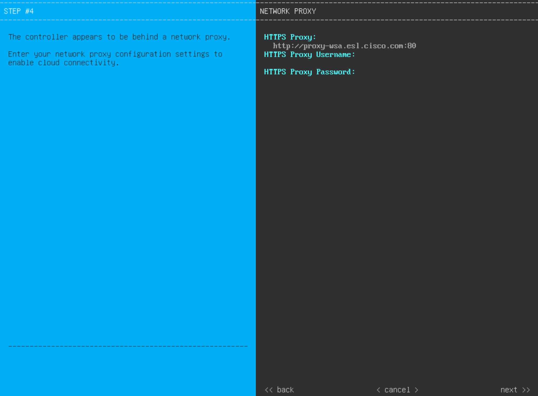
After the network adapter configuration is complete, the wizard prompts you to enter configuration values for the NETWORK PROXY that you are using, as shown.
Enter the configuration values for the NETWORK PROXY, as shown in this table.
Table 5. Primary node entries for network proxy
HTTPS Proxy field
Enter the URL or host name of an HTTPS network proxy used to access the Internet.
Note
Connection from Catalyst Center to the HTTPS proxy is supported only through HTTP in this release.
If you enter an IPv6 URL that contains a port number, enclose the IP address portion of the URL in square brackets. In this
example, 443 is the port number: http://[2001:db8:85a3:8d3:1319:8a2e:370:7348]:443/
HTTPS Proxy Username field
Enter the user name used to access the network proxy. If no proxy login is required, leave this field blank.
HTTPS Proxy Password field
Enter the password used to access the network proxy. If no proxy login is required, leave this field blank.
After you provide the necessary information, click next>> to continue. Correct validation errors, if any, as you did in previous screens.
Step 14
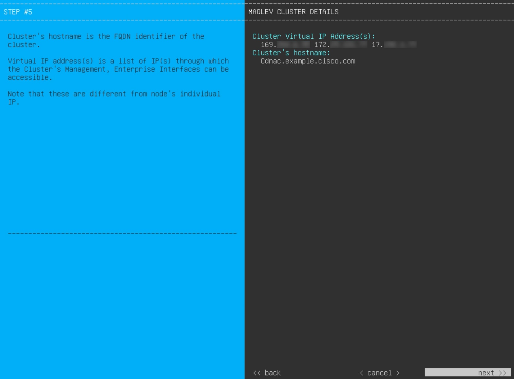
After network proxy configuration completes, the wizard prompts you to enter virtual IP addresses for the primary node, in
MAGLEV CLUSTER DETAILS, as shown.
Enter a space-separated list of the virtual IP addresses used for traffic between the cluster and your network. This is required
for both three-node clusters and single-node clusters that will be converted into a three-node cluster in the future. If you
have a single-node cluster setup and plan to stick with it, skip this step and continue to the next step.
Important
You must enter one virtual IP address for each configured network interface. You will not be able to complete the wizard unless
you do so. These addresses are tied to the cluster link's status, which must be in the UP state.
You can also specify a fully qualified domain name (FQDN) for your cluster. Catalyst Center uses this domain name to do these tasks:
It uses this hostname to access your cluster’s web interface and the Representational State Transfer (REST) APIs used by devices
in the enterprise network that Catalyst Center manages.
In the Subject Alternative Name (SAN) field of Catalyst Center certificates, the FQDN defines the Plug and Play server used for device provisioning.
After you provide the necessary information, click next>> to continue. Correct validation errors, if any, as you did in previous screens.
Step 15
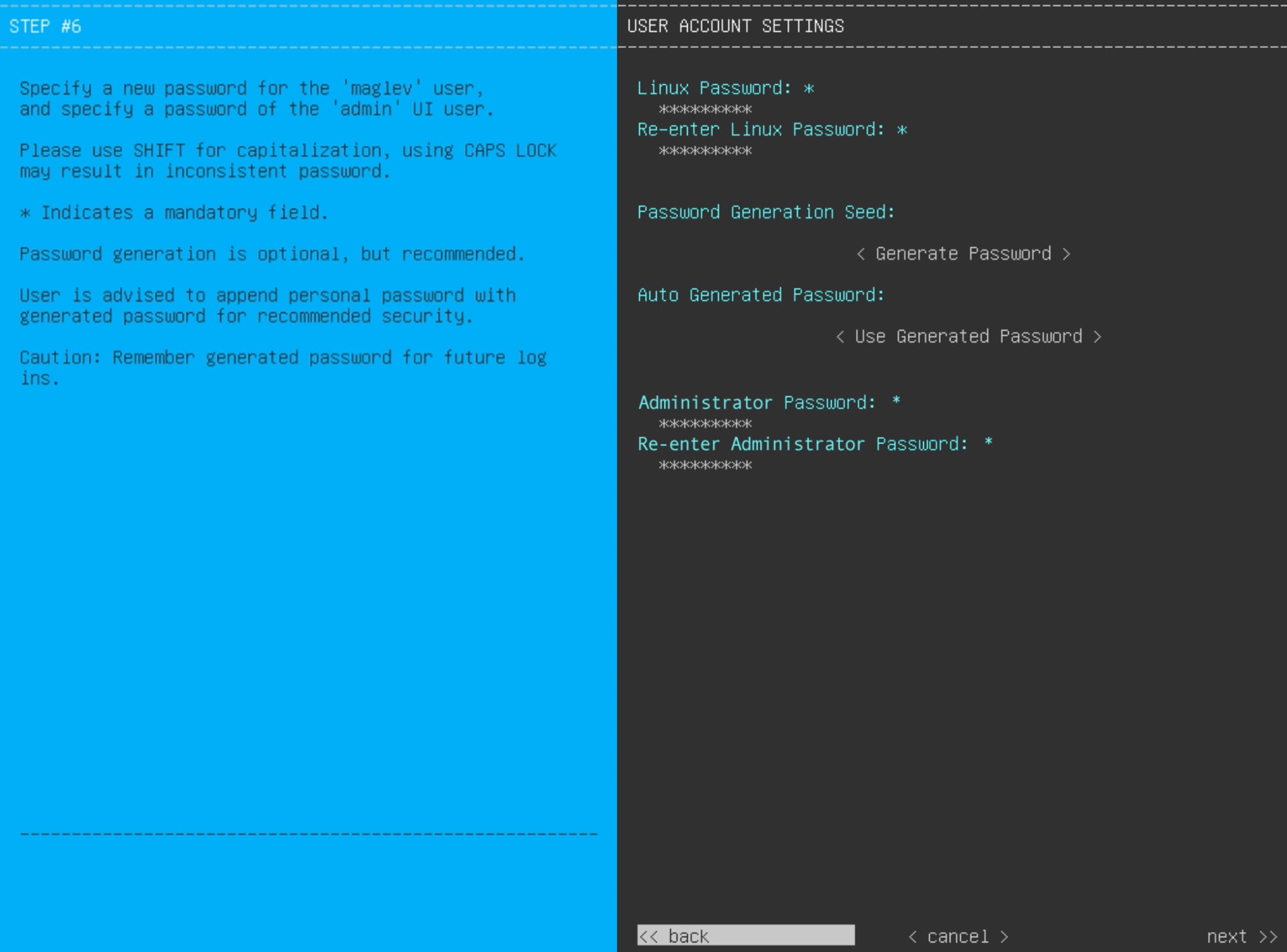
After you have entered the cluster details, the wizard prompts you to enter USER ACCOUNT SETTINGS values, as shown.
This table lists the configuration values for USER ACCOUNT SETTINGS to enter.
Table 6. Primary node entries for user account settings
Linux Password field
Enter a Linux password for the maglev user that complies with the Password requirements.
Re-enter Linux Password field
Confirm the Linux password by entering it a second time.
Password Generation Seed field
To generate a Linux password automatically, enter a seed phrase in this field and then press <Generate Password>.
Auto Generated Password field
(Optional) The generated password includes the seed phrase. You may use this password or edit the auto-generated password.
Press <Use Generated Password> to save the password.
Administrator Password field
Enter a password for the default admin superuser, used to log in to Catalyst Center for the first time. Ensure that this password complies with the Password requirements.
Note
If you select the Start using DNAC pre manufactured cluster option previously, the default password (P@ssword9) has already been set for the appliance and cannot be changed in the configuration wizard. As a result, this and the next
field are not displayed in this screen.
Re-enter Administrator Password field
Confirm the administrator password by entering it a second time.
After you provide the necessary information, click next>> to continue. Correct validation errors, if any, as you did in previous screens.
Step 16
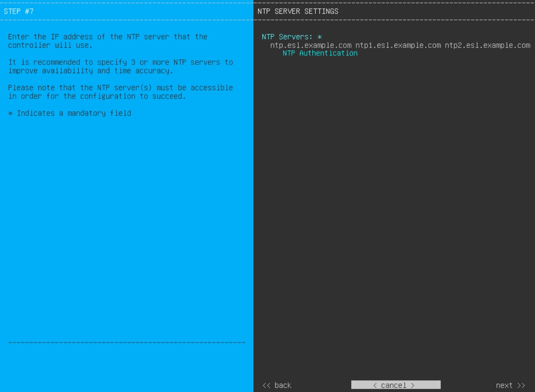
After you have entered the user account details, the wizard prompts you to enter NTP SERVER SETTINGS values.
This table lists the configuration values for NTP SERVER SETTINGS to enter.
NTP Servers field
Enter one or more NTP server addresses or hostnames, separated by spaces. At least one NTP address or hostname is required.
For a production deployment, we recommend that you configure a minimum of three NTP servers.
NTP Authentication check box
To enable the authentication of your NTP server before it's synchronized with Catalyst Center, check this check box and then enter this information:
The NTP server's key ID. Valid values range between 1 and 4294967295 (2^32-1).
This value corresponds to the key ID that's defined in the NTP server's key file.
The SHA-1 key value associated with the NTP server's key ID. This 40-character hex string resides in the NTP server's key
file.
Note
Ensure that you enter a key ID and key value for each NTP server that you configured in the previous field.
After you provide the necessary information, click next>> to continue. Correct validation errors, if any, as you did in previous screens. The wizard validates and applies your NTP
server configuration.
Step 17
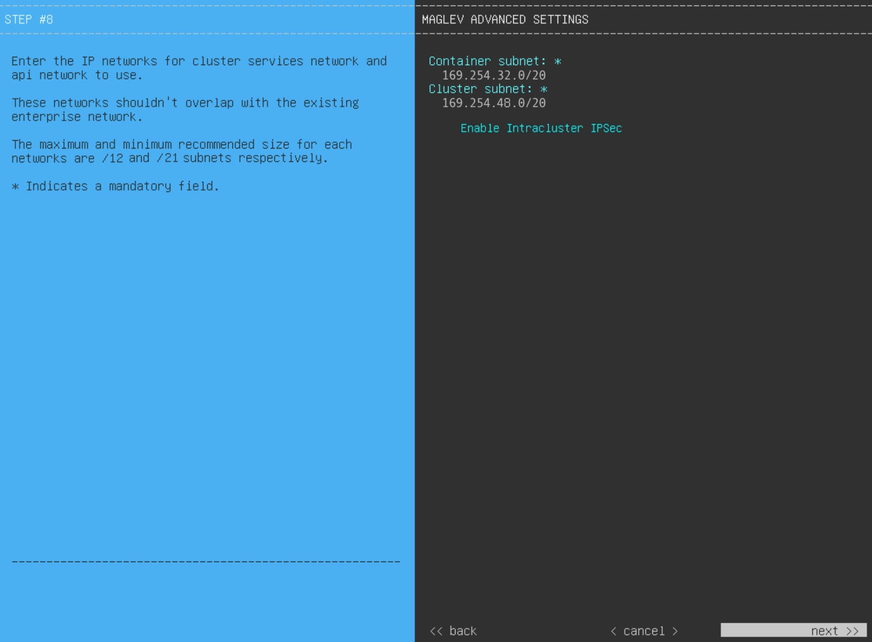
After you have specified the appropriate NTP servers, the wizard prompts you to enter MAGLEV ADVANCED SETTINGS values, as shown.
Note
If you chose the Start using DNAC pre manufactured cluster option previously, the default Container and Cluster subnets have already been set for the appliance and cannot be changed
in the configuration wizard. As a result, you will not see this wizard screen. Continue to Step 17.
This table lists the configuration values for MAGLEV ADVANCED SETTINGS to enter.
Table 7. Primary node entries for Maglev advanced settings
Container Subnet field
A dedicated, non-routed IP subnet that Catalyst Center uses to manage internal services. By default, this is already set to 169.254.32.0/20, and we recommend that you use this subnet. If you decide to enter another subnet, ensure that it does not conflict with
or overlap any other subnet used by the Catalyst Center internal network or an external network. For more information, see the Container Subnet description in Required IP addresses and subnets.
Cluster Subnet field
A dedicated, non-routed IP subnet that Catalyst Center uses to manage internal cluster services. By default, this is already set to 169.254.48.0/20, and we recommend that you use this subnet. If you decide to enter another subnet, ensure that it does not conflict with
or overlap any other subnet used by the Catalyst Center internal network or an external network. For more information, see the Cluster Subnet description in Required IP addresses and subnets.
Enable Intracluster IPSec check box
Check to enable IPsec connections between the nodes in a three-node high HA cluster.
When you are finished, click next>> to continue. Correct validation errors, if any, as you did in previous screens.
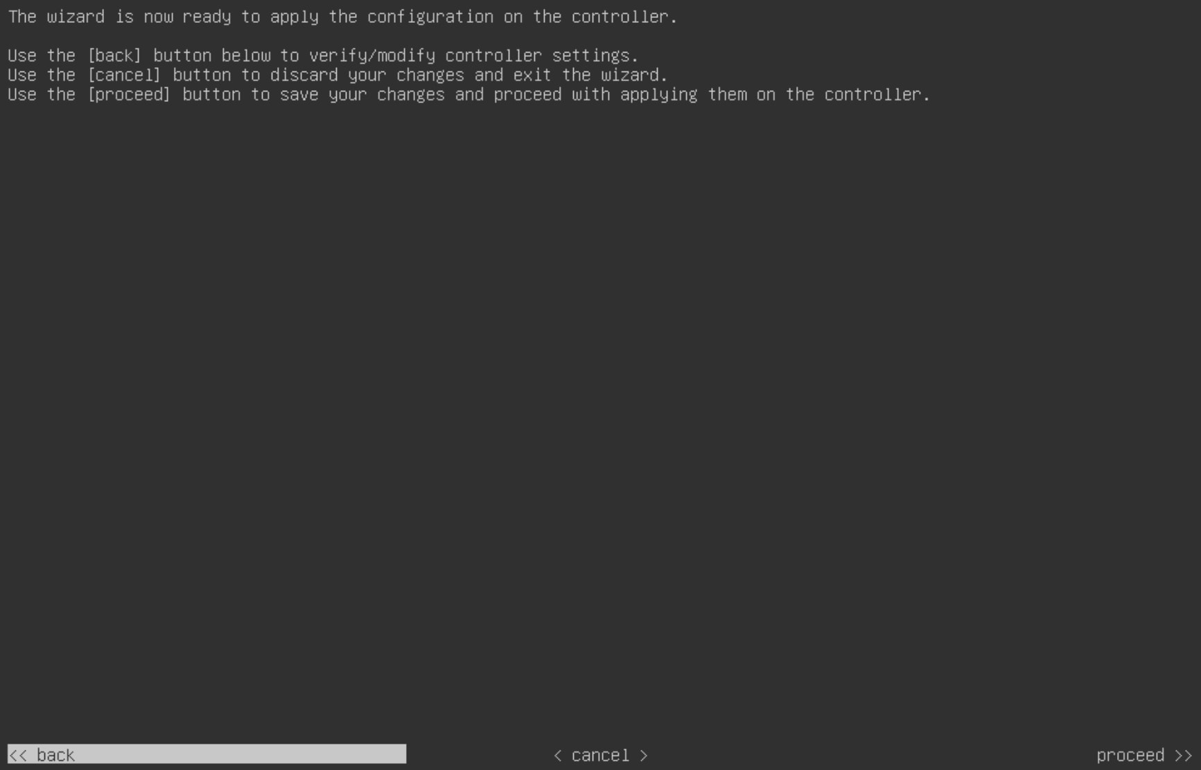
Step 18
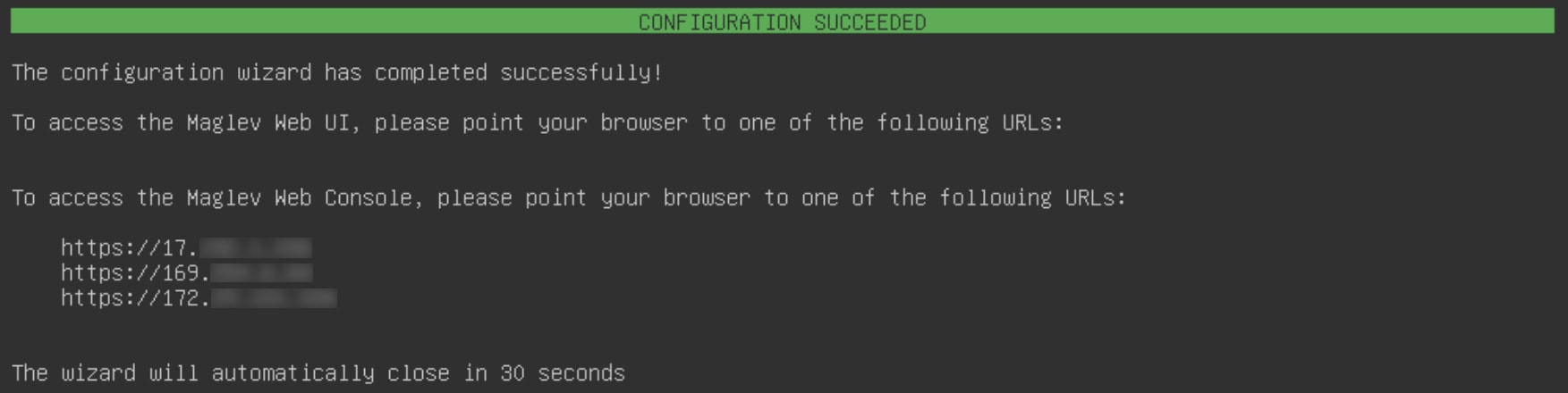
After you have entered the Maglev advanced settings, a final message appears, stating that the wizard is ready to apply the
configuration (as shown).
Click proceed>> to complete the configuration wizard.
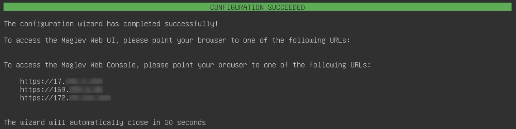
The host will reboot automatically and display messages on the KVM console as it applies your settings and brings up services.
This process can take several hours. You can monitor its progress using the KVM console.
At the end of the configuration process, the appliance power cycles again, then displays a CONFIGURATION SUCCEEDED! message.
What to do next
If you are deploying this appliance in standalone mode only, do the first-time setup: First-time setup workflow.
Catalyst Center supports the Federal Information Processing Standard (FIPS), a government certification standard that specifies best practices
for implementing cryptographic algorithms, handling key material and data buffers, and working with the operating system.
Understand these points if you plan to enable FIPS mode on an appliance:
You cannot enable FIPS mode on an appliance that has been upgraded from a previous Catalyst Center version. You can only enable it on an appliance that came with the latest version already installed.
When FIPS mode is enabled, you cannot import images from a URL. You can only import images from either your computer or cisco.com.
In the USER ACCOUNT SETTINGS screen, you will need to enter a password for the default admin superuser that complies with the Password requirements.
When FIPS mode is enabled on an appliance, you cannot enable external authentication.
A backup can only be restored on a Catalyst Center cluster that has the same FIPS mode setting configured as the source cluster. Backup and restore operations involving clusters
with different FIPS mode settings will fail (since Catalyst Center will label backups as incompatible).
If you selected the Start using DNAC pre manufactured cluster option while completing the Maglev Configuration wizard, the IP addressing and Security mode used for the services screen does not appear. You cannot enable FIPS mode in this scenario.
Catalyst Center does not support SNMPv2c device credentials when FIPS mode is enabled. You must specify SNMPv3 credentials instead.
After FIPS mode has been enabled on an appliance, the only way you can disable it is to reimage your appliance, which erases
all existing data. You can then reconfigure the appliance with FIPS mode disabled. See Reimage the appliance for more information.
When FIPS mode is enabled, you can enable KeyWrap only if Catalyst Center and Cisco ISE have not been integrated. See Configure authentication and policy servers for more information.
After configuring your appliance, do these steps to confirm whether FIPS mode is enabled:
Open an SSH console to the appliance and run the ssh -p 2222 maglev@appliance's-IP-address command.
Enter the default admin superuser's password to log in to the appliance.
Run the magctl fips status command.
The Cisco Wide Area Bonjour application does not support FIPS mode. As a result, you cannot install this application from
either the Catalyst Center GUI or CLI.
When FIPS mode is enabled, some of the functions related to Endpoint Analytics are unavailable in the Catalyst Center GUI.
FIPS mode affects the export and import of map archives.
When FIPS mode is enabled:
Exported map archives are unencrypted.
Only unencrypted map archives can be imported.
When FIPS mode is disabled:
Exported map archives are encrypted.
Both encrypted and unencrypted map archives can be imported.
Configure a secondary node using the Maglev wizard
Do the steps in this procedure to configure the second and third appliances in the cluster.
Important
In order to build a three-node cluster, the same version of the System package must be installed on your three Catalyst Center appliances. Otherwise, unexpected behavior and possible downtime can occur.
Before you configure the appliances in a three-node cluster, ensure that you have logged out of those appliances. Otherwise,
the Quick Start workflow (which you complete to discover your network's devices and enable telemetry) will not start after
you have configured your cluster's appliances and log in to Catalyst Center for the first time.
Ensure that all of the IP addresses you enter while completing this procedure are valid addresses with valid netmasks. Also
make sure that the addresses and their corresponding subnets do not overlap. Service communication issues can result if they
do.
When joining each new secondary node to the cluster, you must specify the physical IP address of the cluster link of the first
host in the cluster.
If you are replacing a node in an HA-enabled cluster, use the physical IP address of the cluster link of either of the remaining
nodes.
When joining secondary nodes to a cluster, understand:
Be sure to join only a single node to the cluster at a time. Do not attempt to add multiple nodes at the same time, because
this results in unpredictable behavior.
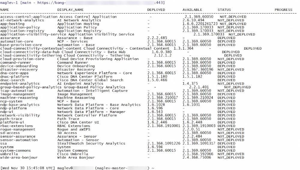
Before adding a new node to the cluster, be sure that all installed packages are deployed on the primary node. You can check
this by using Secure Shell to log in to the primary node's Catalyst Center Management port as the Linux user (maglev) and then running the command maglev package status. All installed packages should appear in the command output as DEPLOYED.
Expect some service downtime during the cluster attachment process for each secondary node. Services will need to be redistributed
across the nodes, and the cluster will be down for periods of time during that process.
Ran the maglev package status command on the first appliance.
You can also access this information from the Catalyst Center GUI by clicking the Help icon () and choosing About > Packages.
Contacted the Cisco TAC, gave them the output of this command, and asked them to point you to the ISO that you should install
on your second and third appliances.
Checked that both the secondary appliances' ports and the switches they use are properly configured (as described in Execute preconfiguration tasks).
Confirmed that you are using a compatible browser. For a list of compatible browsers, see the Release Notes document for the version of Catalyst Center you are installing.
Enabled ICMP on the firewall between Catalyst Center and both the default gateway and the DNS server you specify in this procedure. The Maglev Configuration wizard uses ping
to verify the gateway and DNS server you specify.
Caution
This ping might get blocked if a firewall is in place and ICMP is not enabled on that firewall. When this happens, you will
not be able to complete the wizard.
After successful login, the appliance displays the Cisco Integrated Management Controller Chassis Summary window, with a hyperlinked menu at the top of the window.
Step 2
From the hyperlinked menu, select Launch KVM and then select HTML based KVM.
The KVM console opens in a separate window or tab automatically. Use it to monitor the progress of the configuration and respond
to the Maglev Configuration wizard prompts.
Step 3
With the KVM displayed, reboot the appliance by selecting one of these options:
In the main Cisco IMC GUI browser window: Choose Host Power > Power Cycle, and switch to the KVM console to continue.
In the KVM console: Choose Power > Power Cycle System (cold boot).
If you are asked to confirm your choice to reboot the appliance, click OK.
After displaying reboot messages, the KVM console displays the Static IP Configuration screen.
Step 4
Click Skip.
The KVM console displays the Maglev Configuration wizard welcome screen.
Note
Only users that want to configure their appliance using one of the browser-based wizards without using the IP address, subnet
mask, and default gateway assigned to the appliance's Enterprise interface by a DHCP server need to complete this screen.
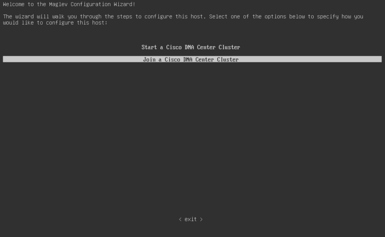
Step 5
Click Join a Catalyst Center Cluster to begin configuring the secondary node.
The screen updates.
Step 6
Do these steps, then click next>> to continue:
Specify whether the applications and services running on your Catalyst Center appliance will use IPv4 or IPv6 addressing.
(Optional) Check the Enable FIPS Mode check box to enable FIPS mode on your Catalyst Center appliance.
See FIPS mode support for things to keep in mind when enabling FIPS mode on an appliance.
Important
In the next wizard screen, you can enable the VLAN mode feature, which creates a single bonded interface that connects to your network using both the primary and secondary instance
of your appliance's Enterprise interface. This feature is not commonly used, so only enable it if you know it's required by
your Catalyst Center deployment.
If this is the case, complete the next step.
Otherwise, click next>> in the next wizard screen without making any selections. You can enable the NIC bonding functionality that was described
previously in this guide in the wizard's Enterprise and Intracluster interface configuration screens.
Step 7
(Optional) Do these steps to enable Layer 2 port channel mode (with VLAN tagging) for the appliance. After making your selections,
click next>> to continue.
Select the VLAN mode option to enable dot1q/VLAN trunking and convert your appliance's Enterprise, Cluster, Management, and Internet interfaces
into VLAN subinterfaces that reside on the bonded interface (as illustrated in this figure). By default, this interface operates
in Active-Backup mode (which enables HA).
If you want this interface to operate in LACP mode instead (which enables load balancing and higher bandwidth), you must also
select the LACP option.
When you enter the settings for your appliance's Enterprise and Cluster interfaces, ensure that you enter a unique VLAN ID
in the VLAN ID of Interface field for the subinterfaces you want to configure on the virtual bonded interface.
Important
Even though one physical appliance interface (the Enterprise interface) is connected, you can configure all of the subinterfaces
that reside on the virtual bonded interface.
The wizard discovers all of the ports on the appliance and presents them to you one by one, in separate screens, in this order:
(Optional) 1-Gbps/10-Gbps Internet port—network adapter #4
If the wizard fails to display either or both of the Enterprise and Cluster ports during the course of configuration, it might
indicate that these ports are nonfunctional or disabled. These two ports are required for Catalyst Center functionality. If you discover that they are nonfunctional, select cancel to exit the configuration wizard immediately. Be sure that you have completed all of the steps provided in Execute preconfiguration tasks before resuming the configuration or contacting the Cisco Technical Assistance Center.
Step 8
The wizard first presents the 10-Gbps Enterprise port as NETWORK ADAPTER #1. As explained in Interface cable connections, this is a required port used to link the appliance to the enterprise network. Apply the host IP address, netmask, and other
values that are appropriate for this purpose (see Required IP addresses and subnets and Required configuration information for the values to enter).
Enter the configuration values for NETWORK ADAPTER #1, as shown in this table.
Table 8. Secondary node entries for network adapter #1: 10 Gbps Enterprise port
Host IPv4/IPv6 Address field
Enter the IP address for the Enterprise port. This is required.
IPv4 Netmask/IPv6 Prefix Length field
Do one of these tasks if you entered an IP address:
If you selected IPv4 addressing, enter the netmask for the port's IP address. This is required.
If you selected IPv6 addressing, enter the prefix length (in bits). Valid values range from 10 through 127.
Default Gateway IPv4/IPv6 address field
Enter a default gateway IP address to use for the port.
Important
Ensure that you enter a default gateway IP address for at least one of your appliance's interfaces. Otherwise, you will not
be able to complete the configuration wizard.
IPv4/IPv6 DNS Servers field
Enter the IP address of the preferred DNS server. If you are entering multiple DNS servers, separate the IP addresses in the
list with spaces.
Important
For each appliance in your cluster, configure a maximum of three DNS servers. Problems can occur if you configure more than
three DNS servers for an appliance.
IPv4/IPv6 Static Routes field
Enter one or more static routes in this format, separated by spaces: <network>/<netmask>/<gateway>. This is usually required on the Catalyst Center Management port only.
Vlan Id of Interface field
Enter the VLAN ID that will be tagged over the LACP link to be created for the appliance you are configuring.
Note
This field is displayed only if you set the Layer 2 LACP port channel mode for the appliance by choosing both options in the
previous step.
Cluster Link field
Leave this field blank. It is required on the Cluster port only.
LACP Mode field
Do one of these tasks:
Leave this field blank and the port will operate in Active-Backup mode. This mode provides fault tolerance by aggregating two Ethernet interfaces into a single logical channel. When the interface
that's currently active goes down, the other interface takes its place and becomes active.
Check the check box to enable LACP mode on this port. This mode aggregates two Ethernet interfaces that share the same speed and duplex settings into a single
logical channel. This provides load balancing and higher bandwidth.
For more information about Catalyst Center's implementation of NIC bonding, see NIC bonding overview.
Note
This field is displayed if you didn't select any of the options in the previous step.
After you finish entering the configuration values, click next>> to continue. The wizard validates the values you entered and issues an error message if any are incorrect. If you receive
an error message, check that the value you entered is correct, then reenter it. If needed, click <<back to reenter it.
Step 9
After successful validation of the Enterprise port values you entered, the wizard presents the 10-Gbps Cluster port and presents
it as NETWORK ADAPTER #2. As explained in Interface cable connections, this port is used to link the appliance to the cluster, so apply the host IP address, netmask, and other values that are
appropriate for this purpose (see Required IP addresses and subnets and Required configuration information for the values to enter).
Enter the configuration values for NETWORK ADAPTER #2, as shown in this table.
Table 9. Secondary node entries for network adapter #2: 10 Gbps Cluster port
Host IPv4/IPv6 address field
Enter the IP address for the Cluster port. This is required.
Note
You cannot change the address of the Cluster port later.
IPv4 Netmask/IPv6 Prefix Length field
Do one of these tasks if you entered an IP address:
If you selected IPv4 addressing, enter the netmask for the port's IP address. This is required.
If you selected IPv6 addressing, enter the prefix length (in bits). Valid values range from 10 through 127.
Default Gateway IPv4/IPv6 address field
Enter a default gateway IP address to use for the port.
Important
Ensure that you enter a default gateway IP address for at least one of your appliance's interfaces. Otherwise, you will not
be able to complete the configuration wizard.
IPv4/IPv6 DNS Servers field
Enter the IP address of the preferred DNS server. If you are entering multiple DNS servers, separate the IP addresses in the
list with spaces.
Important
For each appliance in your cluster, configure a maximum of three DNS servers. Problems can occur if you configure more than
three DNS servers for an appliance.
IPv4/IPv6 Static Routes field
Enter one or more static routes in this format, separated by spaces: <network>/<netmask>/<gateway>. This is usually required on the Management port only.
Vlan Id of Interface field
Enter the VLAN ID that will be tagged over the LACP link to be created for the appliance you are configuring.
Note
This field is displayed only if you set the Layer 2 LACP port channel mode for the appliance by choosing both options in Step
7.
Cluster Link field
Check the check box to set this port as the link to a Catalyst Center cluster. This is required on the Cluster port only.
LACP Mode field
Do one of these tasks:
Leave this field blank and the port will operate in Active-Backup mode. This mode provides fault tolerance by aggregating two Ethernet interfaces into a single logical channel. When the interface
that's currently active goes down, the other interface takes its place and becomes active.
Check the check box to enable LACP mode on this port. This mode aggregates two Ethernet interfaces that share the same speed and duplex settings into a single
logical channel. This provides load balancing and higher bandwidth.
For more information about Catalyst Center's implementation of NIC bonding, see NIC bonding overview.
Note
This field is displayed if you didn't select any of the options in Step 7.
You can only enable LACP mode on your appliance's Intracluster interface during the initial configuration of your appliance.
After you provide the necessary information, click next>> to continue. Correct validation errors, if any, as you did in previous screens. The wizard validates and applies your network
adapter configurations.
Step 10
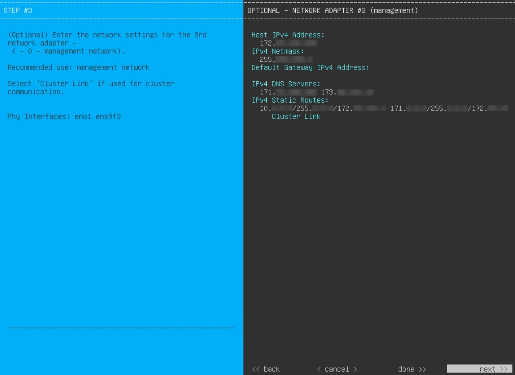
After successful validation of the Cluster port values you entered, the wizard presents the 1 Gbps/10 Gbps Management port
and presents it as NETWORK ADAPTER #3. As explained in Interface cable connections, this port is used to access the Catalyst Center GUI from your management network. Apply the host IP address, netmask, and other values that are appropriate for this purpose
(see Required IP addresses and subnets and Required configuration information for the values to enter).
Enter the configuration values for NETWORK ADAPTER #3, as shown in this table.
Table 10. Secondary node entries for network adapter #3: 1 Gbps/10 Gbps Management port
Host IPv4/IPv6 address field
Enter the IP address for the Management port. This is required only if you are using this port to access the Catalyst Center GUI from your management network; otherwise, you can leave it blank.
IPv4 Netmask/IPv6 Prefix Length field
Do one of these tasks:
If you selected IPv4 addressing, enter the netmask for the port's IP address. This is required.
If you selected IPv6 addressing, enter the prefix length (in bits). Valid values range from 10 through 127.
Default Gateway IPv4/IPv6 address field
Enter a default gateway IP address to use for the port.
Important
Ensure that you enter a default gateway IP address for at least one of your appliance's interfaces. Otherwise, you will not
be able to complete the configuration wizard.
IPv4/IPv6 DNS Servers field
Enter the IP address of the preferred DNS server. If you are entering multiple DNS servers, separate the IP addresses in the
list with spaces.
Important
For NTP, ensure port 123 (UDP) is open between Catalyst Center and your NTP server.
For each appliance in your cluster, configure a maximum of three DNS servers. Problems can occur if you configure more than
three DNS servers for an appliance.
IPv4/IPv6 Static Routes field
Enter one or more static routes in this format, separated by spaces: <network>/<netmask>/<gateway>.
Cluster Link field
Leave this field blank. It is required on the Cluster port only.
After you provide the necessary information, click next>> to continue. Correct validation errors, if any, as you did in previous screens. The wizard validates and applies your network
adapter configurations.
Step 11
After successful validation of the Management port values you entered, the wizard presents the 1 Gbps/10 Gbps Internet port
as NETWORK ADAPTER #4. As explained in Interface cable connections, this is an optional port used to link the appliance to the Internet when you cannot do so through the 10 Gbps Enterprise
port. Apply the host IP address, netmask, and other values that are appropriate for this purpose (see Required IP addresses and subnets and Required configuration information for the values to enter).
Enter the configuration values for NETWORK ADAPTER #4, as shown in this table.
Table 11. Secondary node entries for network adapter #4: 1 Gbps/10 Gbps Internet port
Host IPv4/IPv6 address field
Enter the IP address for the Internet port. This is required only if you are using the Internet port for internet connection;
otherwise, you can leave it blank.
IPv4 Netmask/IPv6 Prefix Length field
Do one of these tasks:
If you selected IPv4 addressing, enter the netmask for the port's IP address. This is required.
If you selected IPv6 addressing, enter the prefix length (in bits). Valid values range from 10 through 127.
Default Gateway IPv4/IPv6 address field
Enter a default gateway IP address to use for the Internet port.
Important
Ensure that you enter a default gateway IP address for at least one of your appliance's interfaces. Otherwise, you will not
be able to complete the configuration wizard.
IPv4/IPv6 DNS Servers field
Enter the IP address of the preferred DNS server. If you are entering multiple DNS servers, separate the IP addresses in the
list with spaces.
Important
For each appliance in your cluster, configure a maximum of three DNS servers. Problems can occur if you configure more than
three DNS servers for an appliance.
IPv4/IPv6 Static Routes field
Enter one or more static routes in this format, separated by spaces: <network>/<netmask>/<gateway>. This is usually required on the Management port only.
Cluster Link field
Leave this field blank. It is required on the Cluster port only.
After you provide the necessary information, click next>> to continue. Correct validation errors, if any, as you did in previous screens. The wizard validates and applies your network
adapter configurations.
Step 12
After the network adapter configuration is complete, the wizard prompts you to enter configuration values for the NETWORK PROXY that you are using, as shown.
Enter the configuration values for the NETWORK PROXY, as shown in this table.
Table 12. Secondary node entries for network proxy
HTTPS Proxy field
Enter the URL or host name of an HTTPS network proxy used to access the Internet.
Note
Connection from Catalyst Center to the HTTPS proxy is supported only through HTTP in this release.
If you enter an IPv6 URL that contains a port number, enclose the IP address portion of the URL in square brackets. In this
example, 443 is the port number: http://[2001:db8:85a3:8d3:1319:8a2e:370:7348]:443/
HTTPS Proxy Username field
Enter the user name used to access the network proxy. If no proxy login is required, leave this field blank.
HTTPS Proxy Password field
Enter the password used to access the network proxy. If no proxy login is required, leave this field blank.
After you provide the necessary information, click next>> to continue. Correct validation errors, if any, as you did in previous screens.
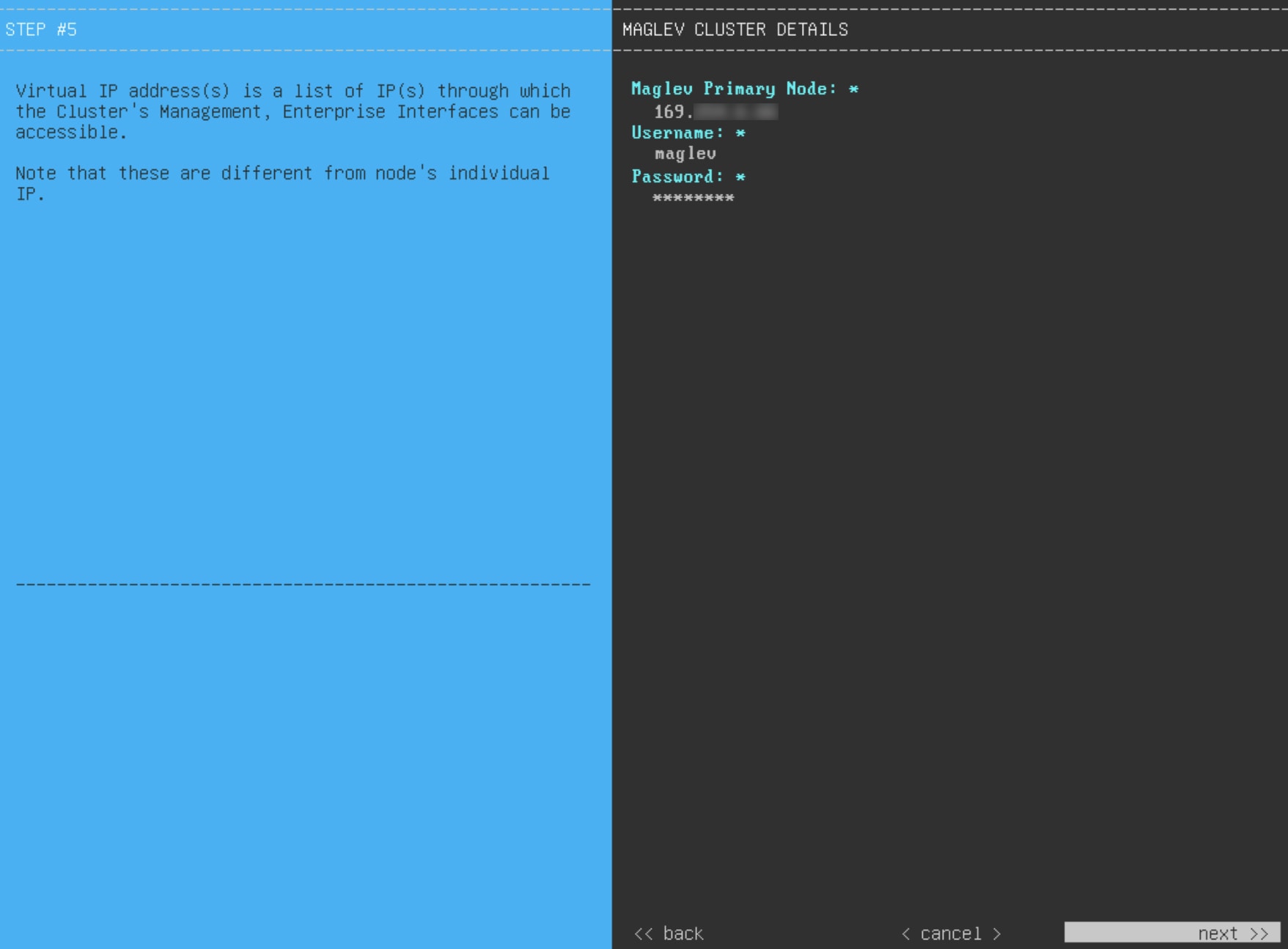
Step 13
After the network proxy configuration completes, the wizard prompts you to identify the Cluster port on the primary node and
primary node login details in MAGLEV CLUSTER DETAILS (as shown).
Enter the values for MAGLEV CLUSTER DETAILS, as shown in this table.
Table 13. Secondary node entries for Maglev cluster details
Maglev Primary Node field
Enter the IP address of the Cluster port on the primary node in the cluster. If you have followed the recommendations for
port assignment, this will be the IP address of Network Adapter #2 on the primary node.
Username field
Enter maglev.
Password field
Enter the Linux password you configured on the primary node.
After you provide the necessary information, click next>> to continue. Correct validation errors, if any, as you did in previous screens.
Step 14
After you have entered the cluster details, the wizard prompts you to enter the USER ACCOUNT SETTINGS values, as shown.
Enter the values for USER ACCOUNT SETTINGS, as shown in this table.
Table 14. Secondary node entries for user account settings
Linux Password field
Enter a Linux password for the maglev user that complies with the Password requirements.
Re-enter Linux Password field
Confirm the Linux password by entering it a second time.
Password Generation Seed field
If you do not want to create the Linux password yourself, enter a seed phrase in this field and then press <Generate Password> to generate the password.
Auto Generated Password field
(Optional) The seed phrase appears as part of a random and secure password. If required, you can either use this password
as is, or you can further edit this auto-generated password.
Click <Use Generated Password> to save the password.
Administrator Password field
Enter a password for the default admin superuser, used to log in to Catalyst Center for the first time. Ensure that this password complies with the Password requirements.
Re-enter Administrator Password field
Confirm the administrator password by entering it a second time.
After you provide the necessary information, click next>> to continue. Correct validation errors, if any, as you did in previous screens.
Step 15
After you have entered the user account details, the wizard prompts you to enter NTP SERVER SETTINGS values.
Enter the values for NTP SERVER SETTINGS, as shown in this table.
NTP Servers field
Enter one or more NTP server addresses or hostnames, separated by spaces. At least one NTP address or hostname is required.
For a production deployment, we recommend that you configure a minimum of three NTP servers.
NTP Authentication check box
To enable the authentication of your NTP server before it's synchronized with Catalyst Center, check this check box and then enter this information:
The NTP server's key ID. Valid values range between 1 and 4294967295 (2^32-1).
This value corresponds to the key ID that's defined in the NTP server's key file.
The SHA-1 key value associated with the NTP server's key ID. This 40-character hex string resides in the NTP server's key
file.
Note
Ensure that you enter a key ID and key value for each NTP server that you configured in the previous field.
After you provide the necessary information, click next>> to continue. Correct validation errors, if any, as you did in previous screens. The wizard validates and applies your NTP
server configuration.
Step 16
When you are finished entering the NTP server settings, a final message appears, stating that the wizard is ready to apply
the configuration (as shown).
Click proceed>> to complete the configuration wizard.
The host will reboot automatically and display messages on the KVM console as it applies your settings and brings up services.
This process can take several hours. You can monitor its progress via the KVM console.
At the end of the configuration process, the appliance power cycles again, then displays a CONFIGURATION SUCCEEDED! message.
What to do next
If you have an additional appliance to deploy as the third and final node in the cluster, repeat this procedure.
If you have finished adding hosts to the cluster, do the first-time setup: First-time setup workflow.


 Feedback