Appliance configuration overview
You can deploy the 32-core or 56-core appliance in your network in one of these modes:
-
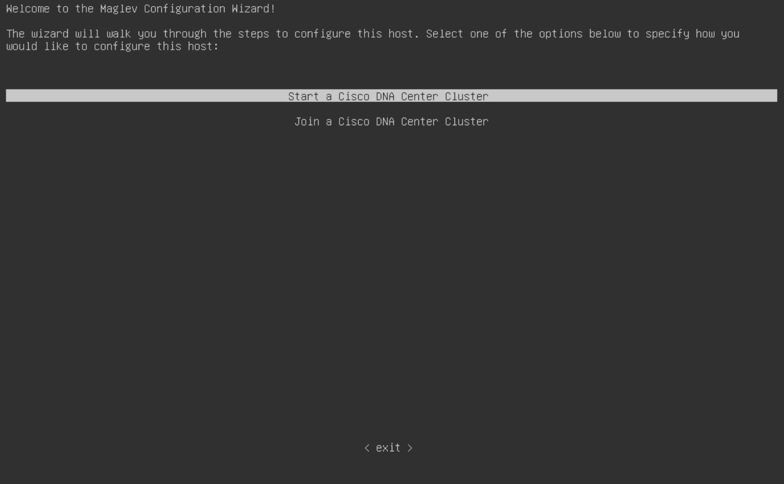
Standalone: As a single node offering all the functions. This option is usually preferred for initial or test deployments and in smaller network environments. If you select the Standalone mode for your initial deployment, it will be your primary node.

Note
You can add more appliances later to form a cluster.
-
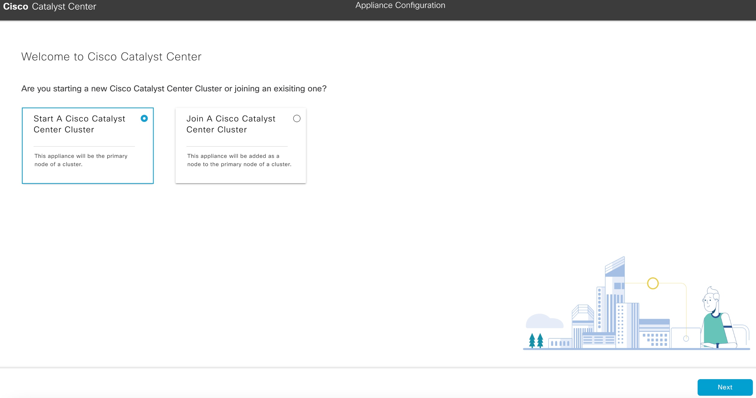
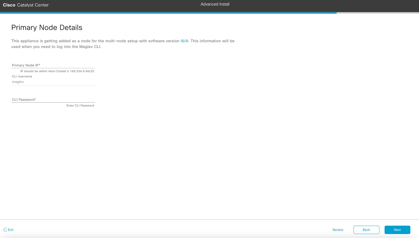
Cluster: As a node that belongs to a three-node cluster. In this mode, all the services and data are shared among the hosts. This is the preferred option for large deployments. If you select the Cluster mode for your initial deployment, be sure to finish configuring the primary node before configuring the secondary nodes.
To continue, configure the primary node in your cluster. If you have installed three appliances and want to add the second and third nodes to your cluster, configure the secondary nodes.
Browser-based configuration wizards
Catalyst Center offers two browser-based wizards that you can use to configure your appliance. Read the descriptions to decide which wizard to complete.
Important |
These wizards are available for use if you are configuring a new appliance that came with the latest 2.3.7.x release of Catalyst Center already installed. If you upgraded from an earlier version and want to use these wizards, contact Cisco TAC for support. |
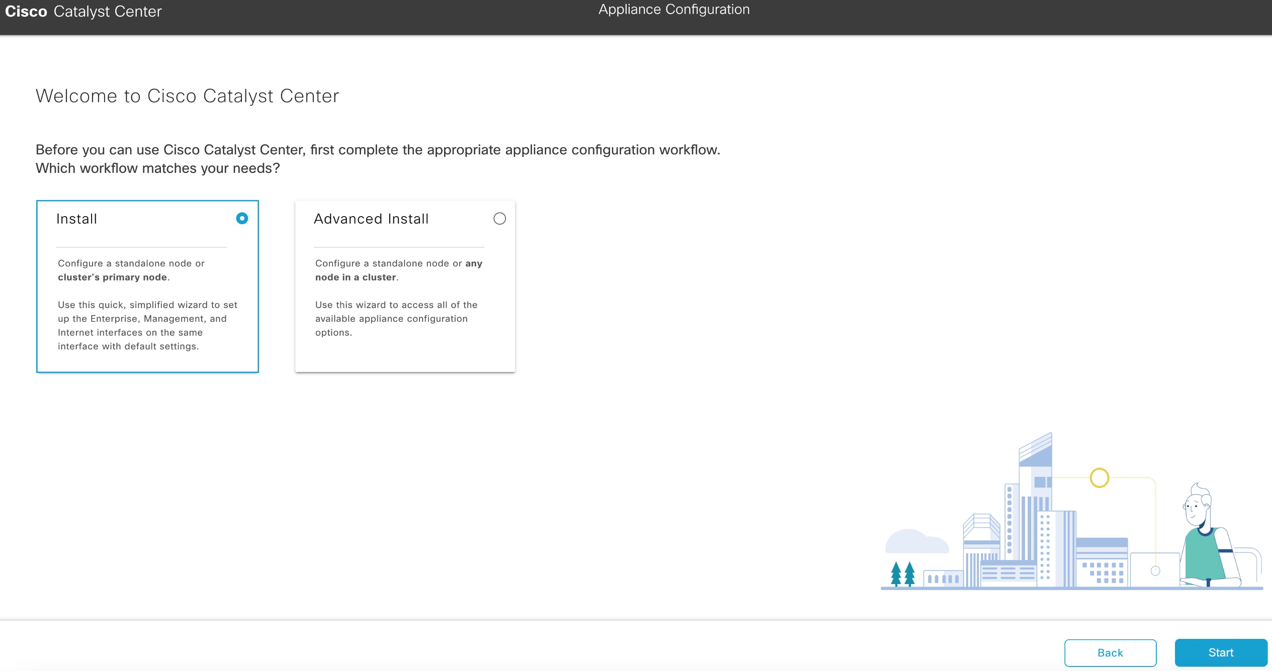
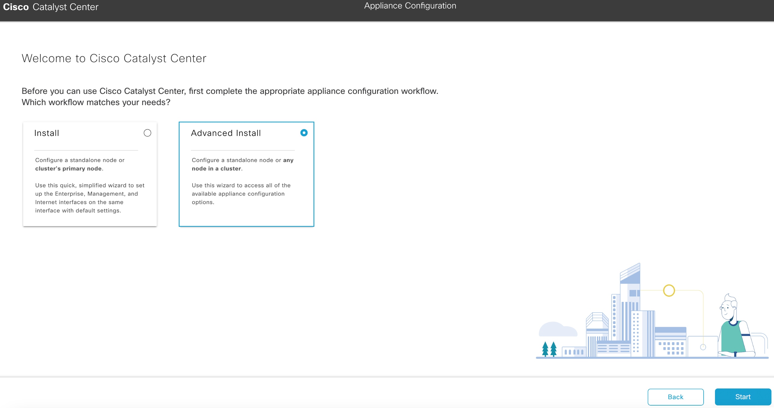
Install configuration wizard
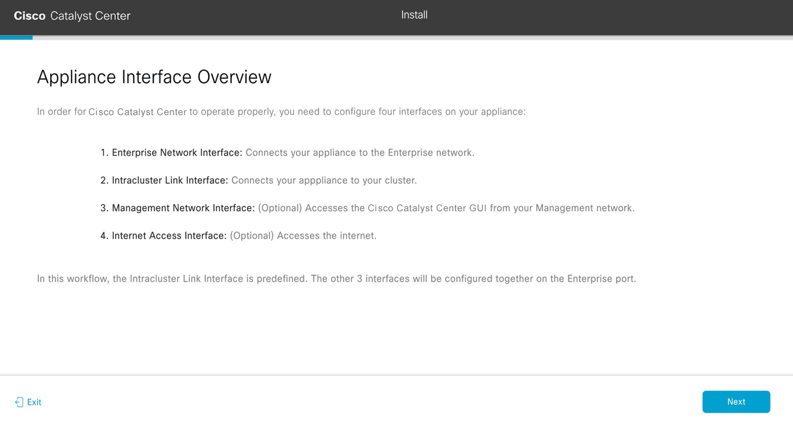
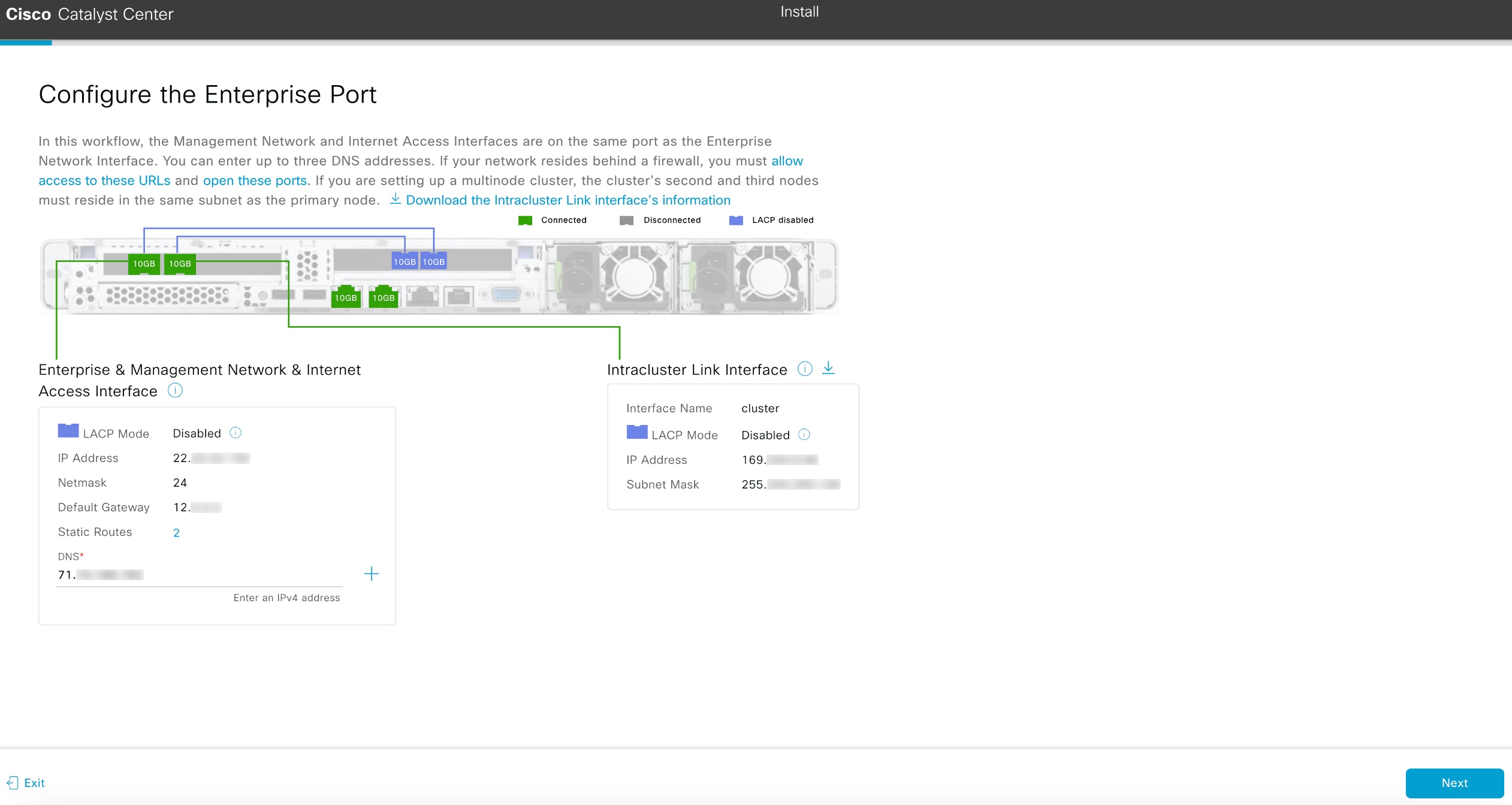
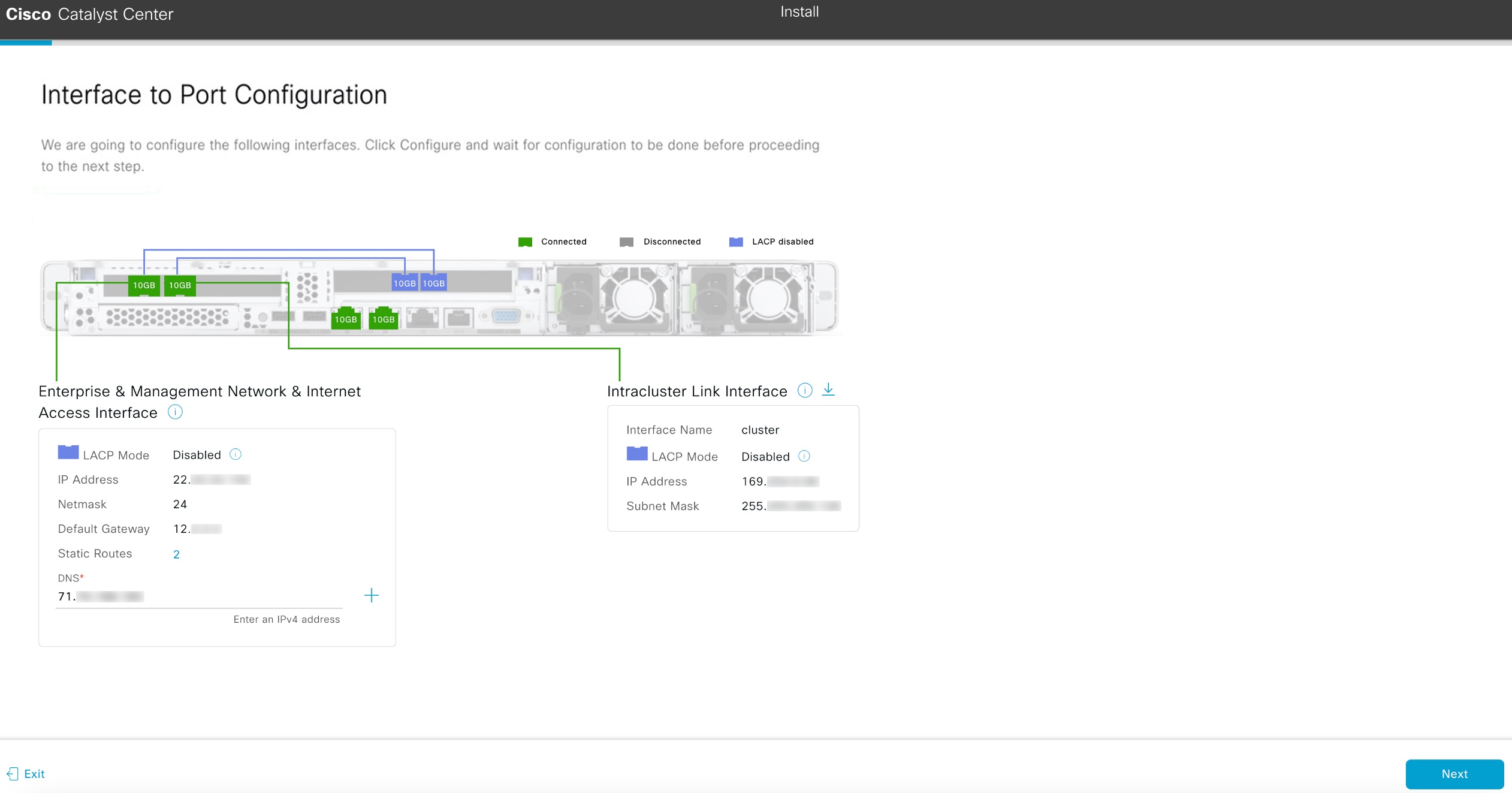
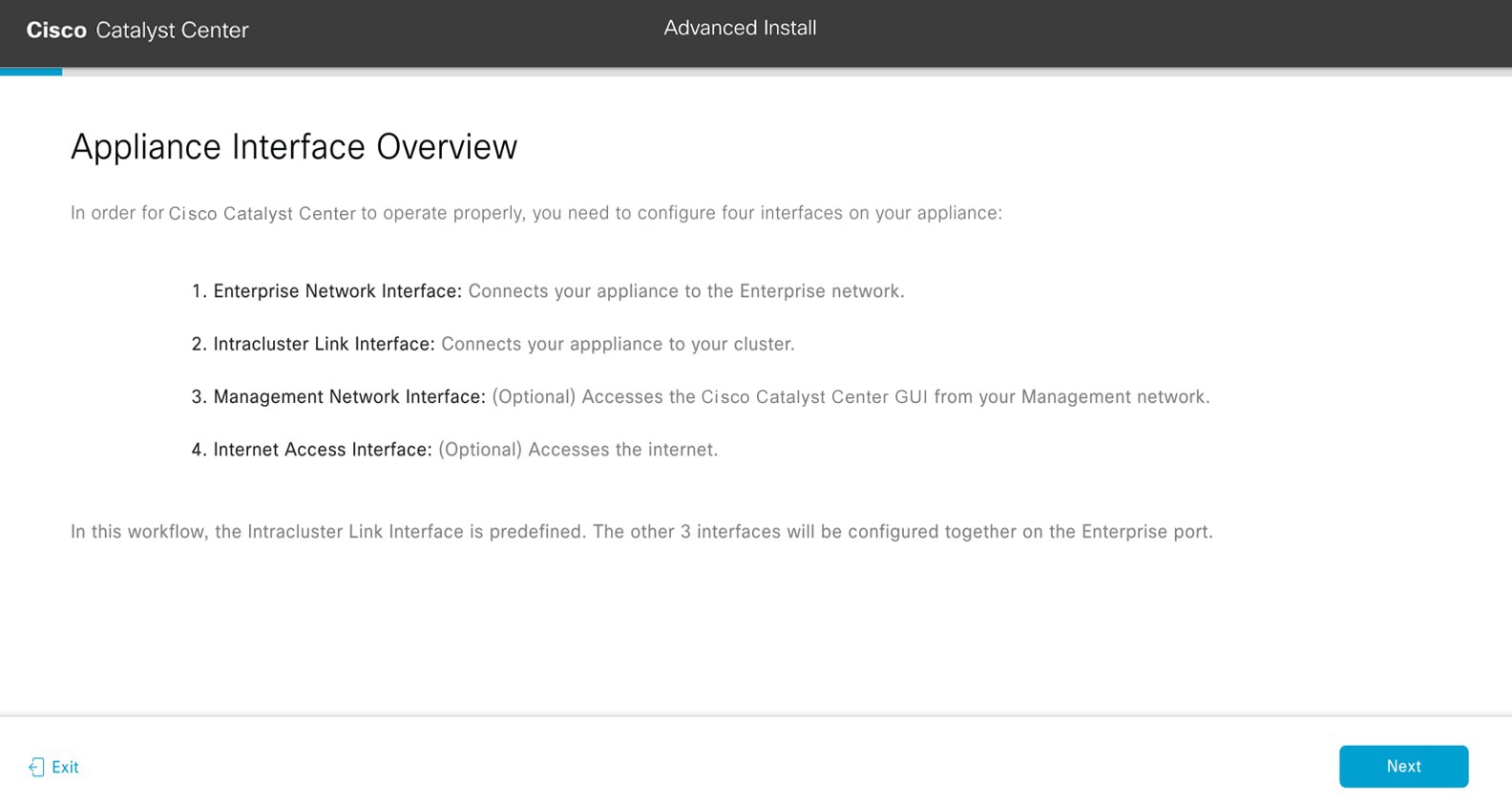
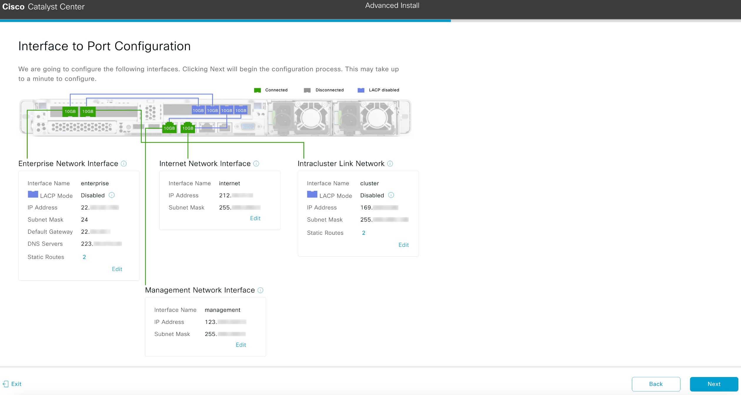
This wizard streamlines the appliance configuration process by setting default values for the Enterprise, Management, and Internet Access interfaces as well as the Intracluster interface. All the interfaces reside on the appliance’s Enterprise port. Use this wizard if you agree to use the default interface settings and want to activate your appliance quickly.
Note |
You cannot use this wizard to configure a cluster’s secondary nodes. |
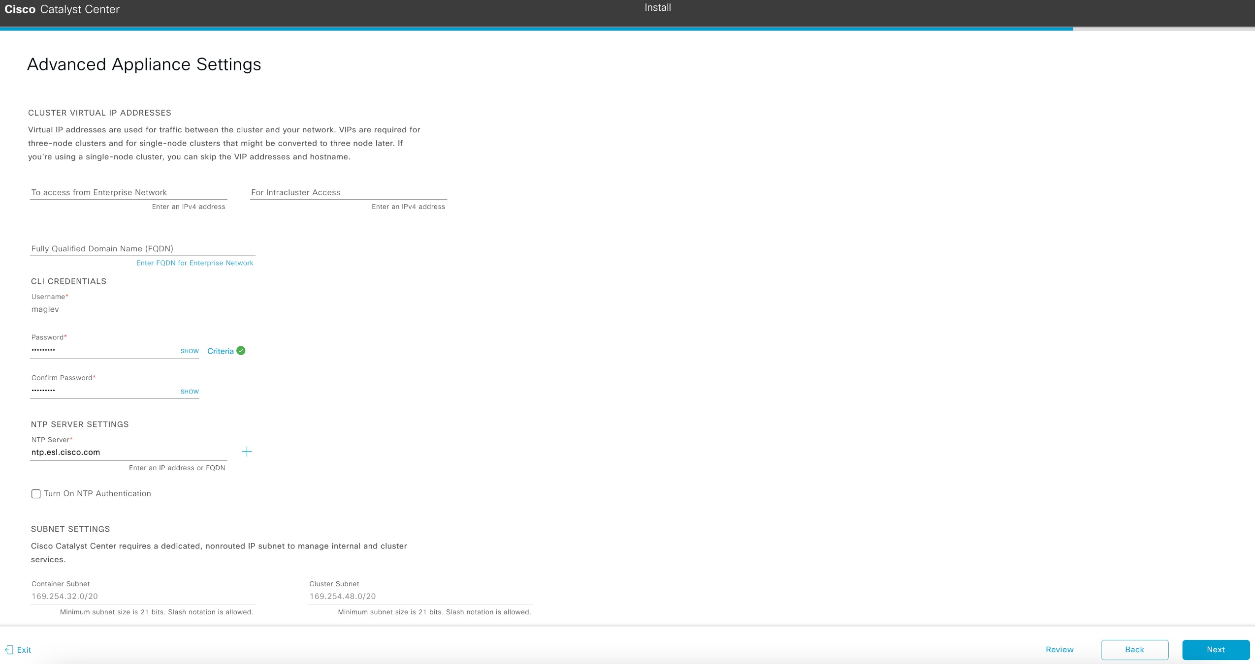
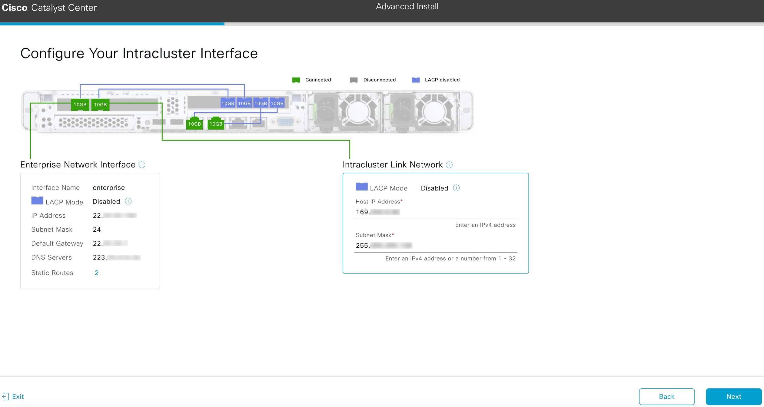
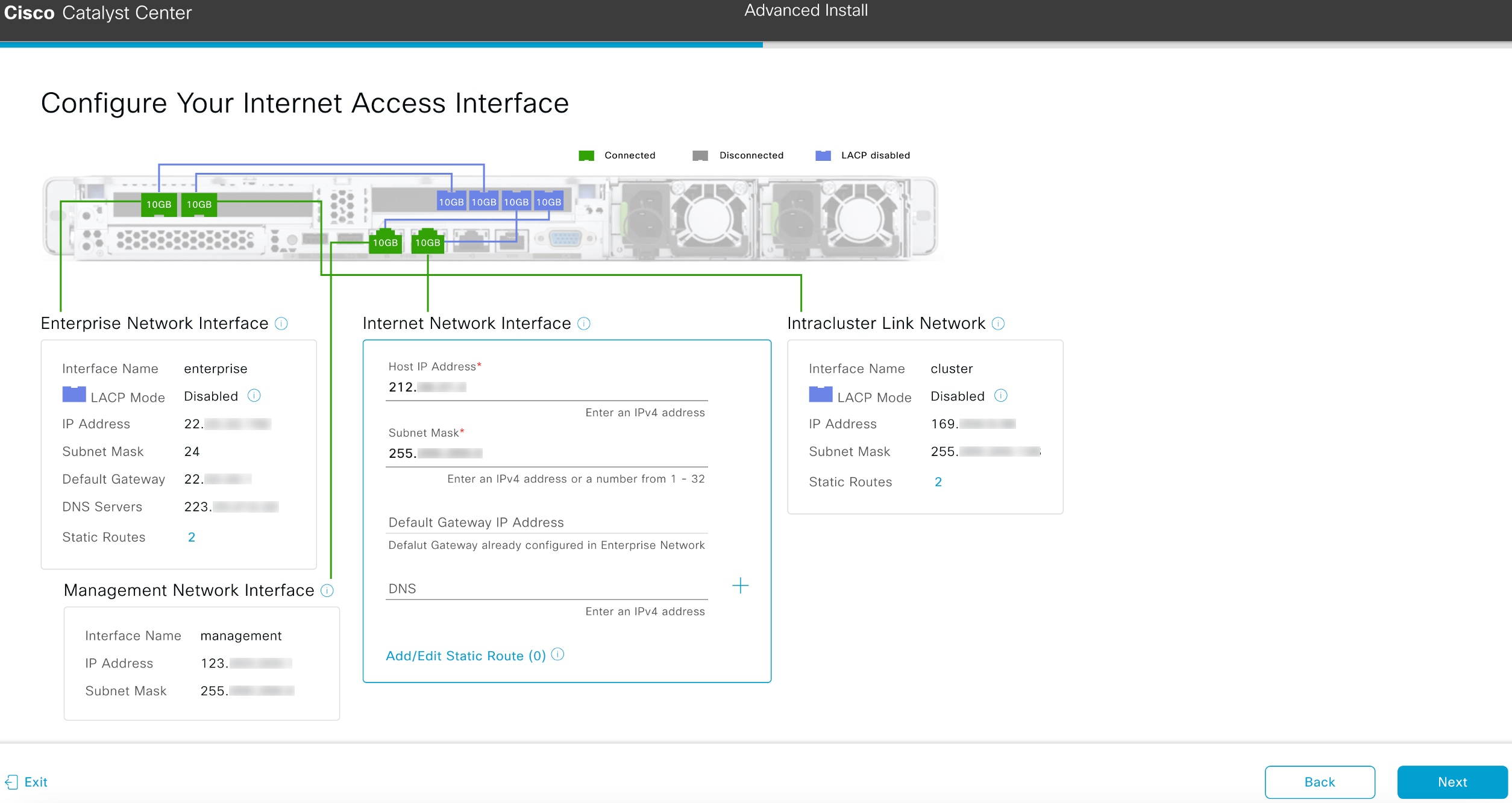
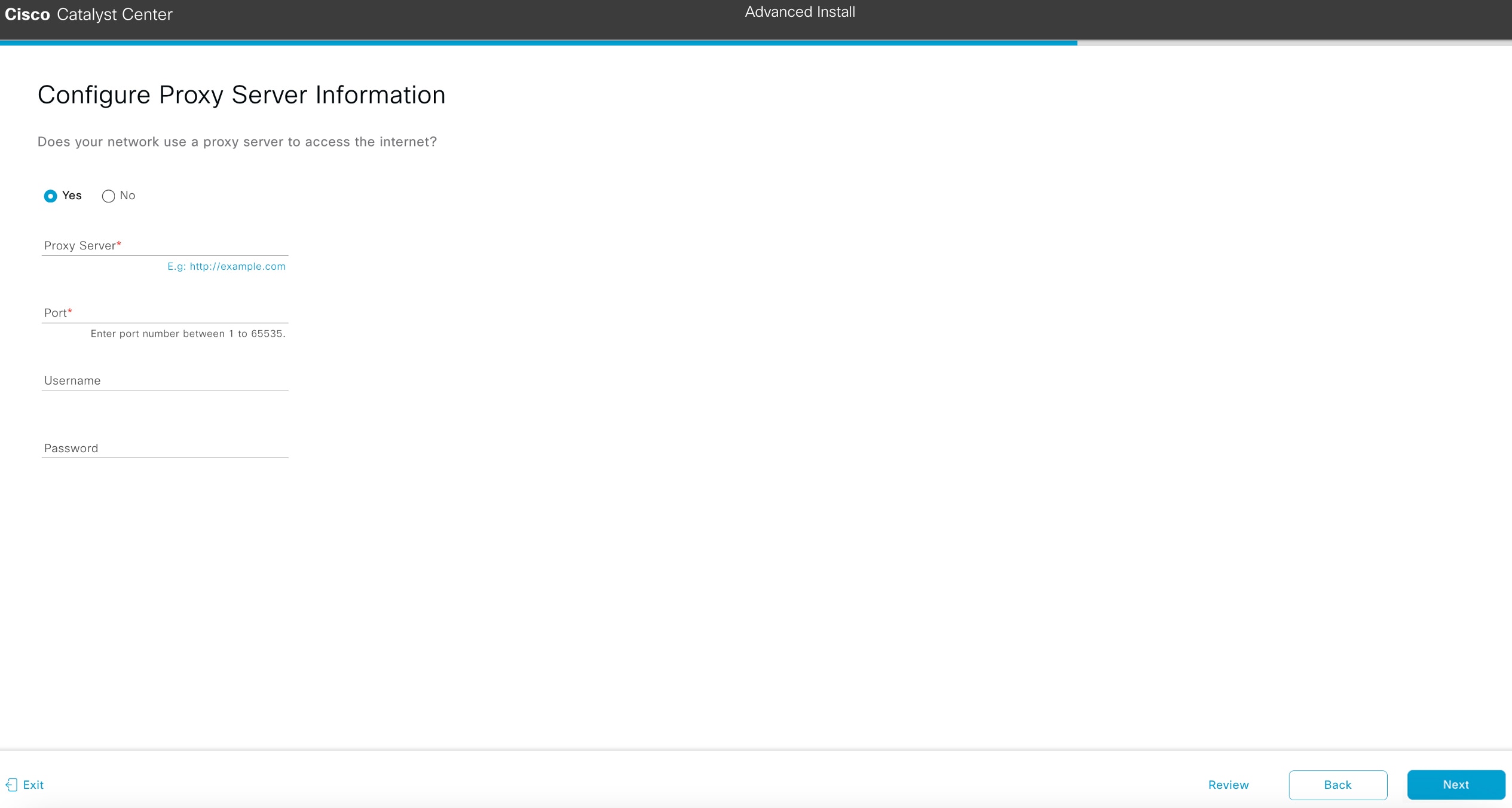
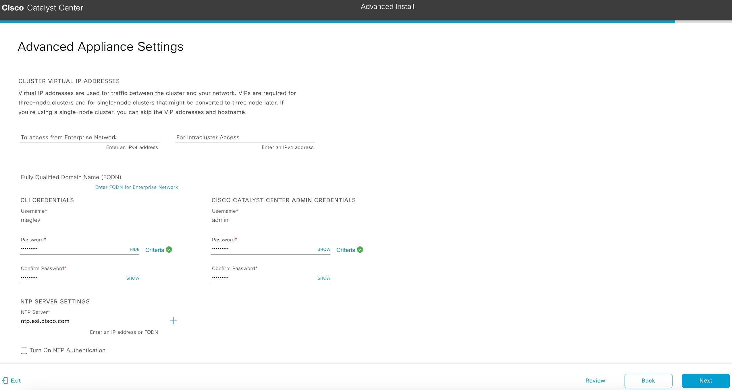
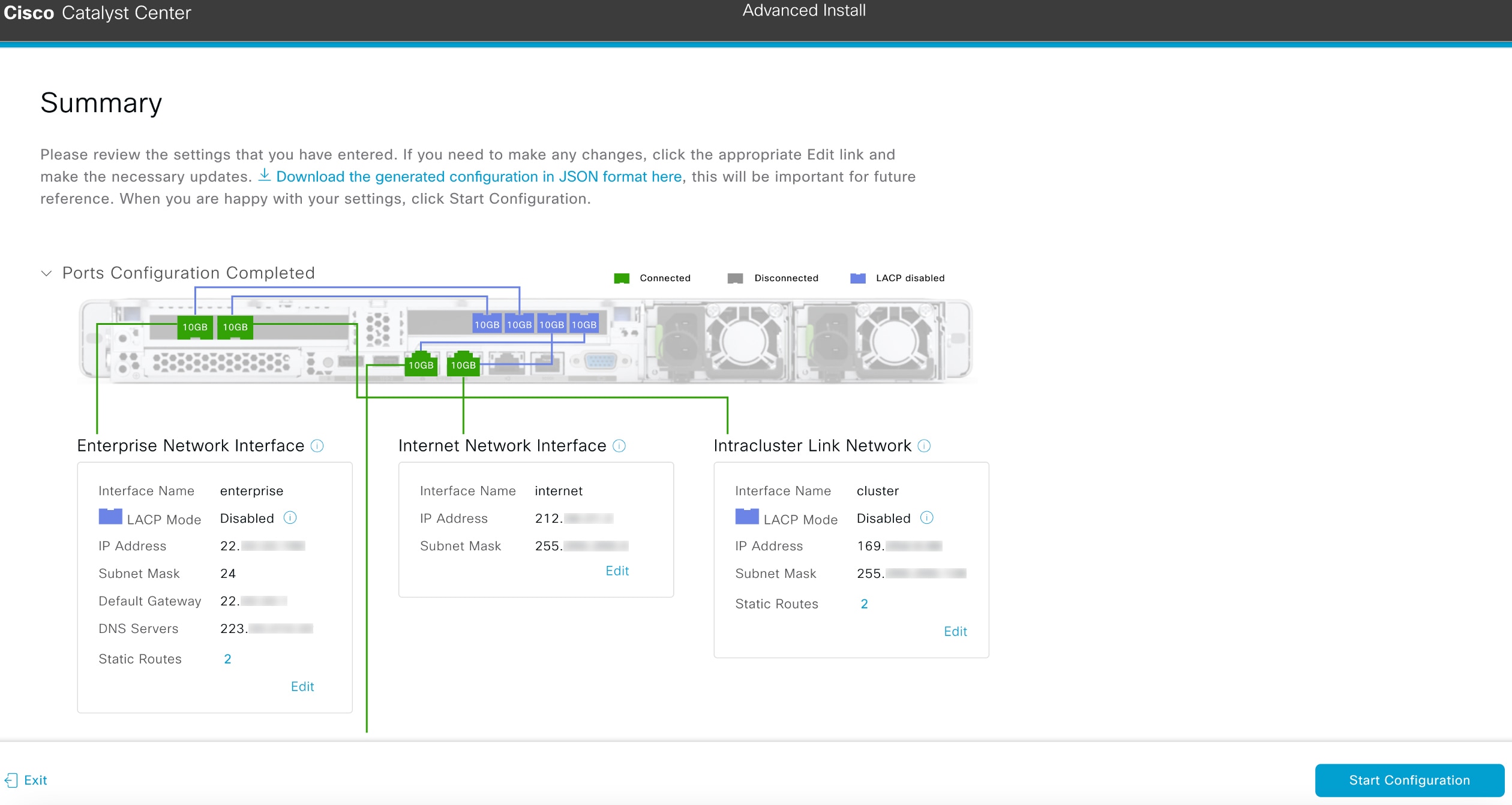
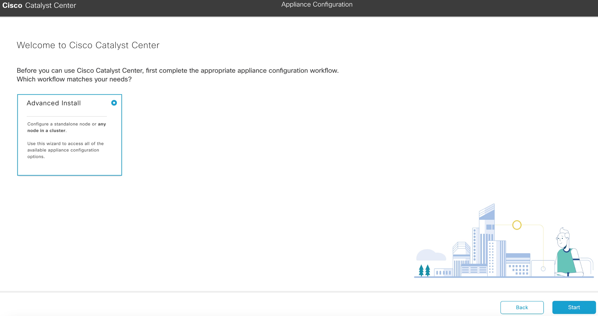
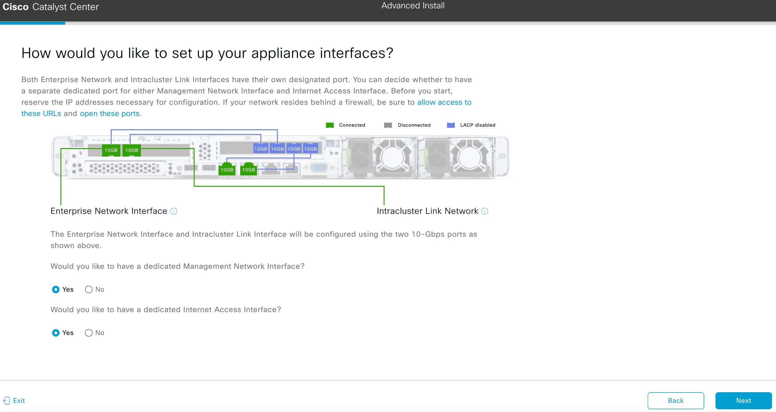
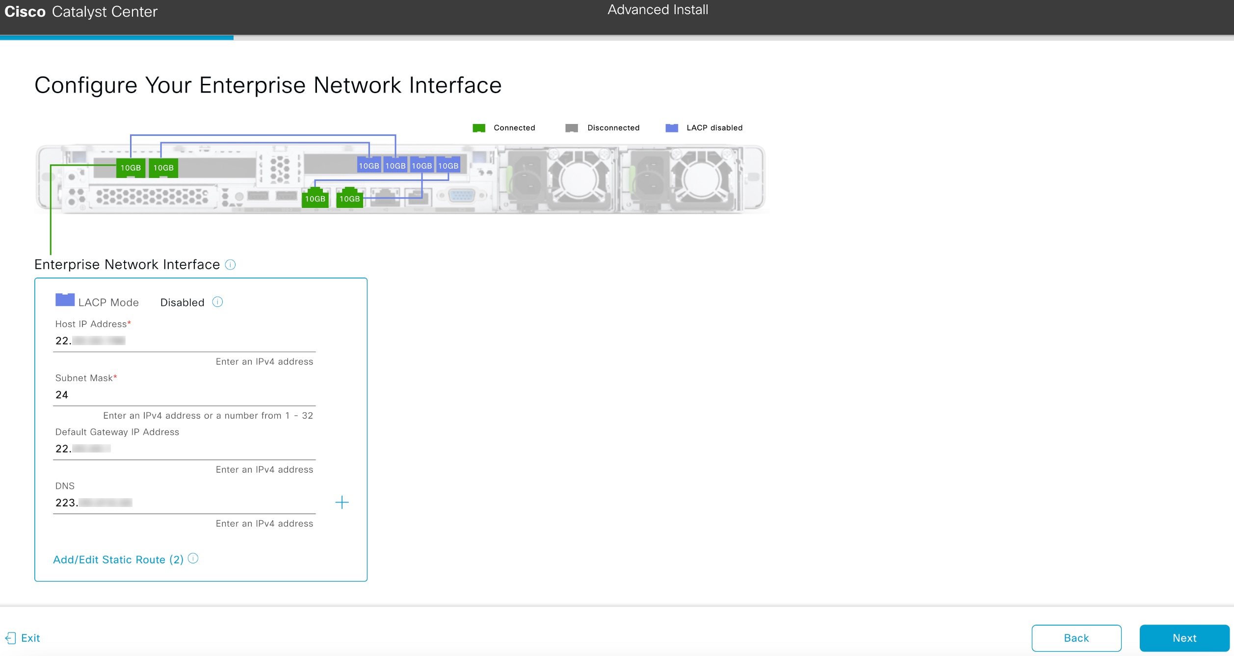
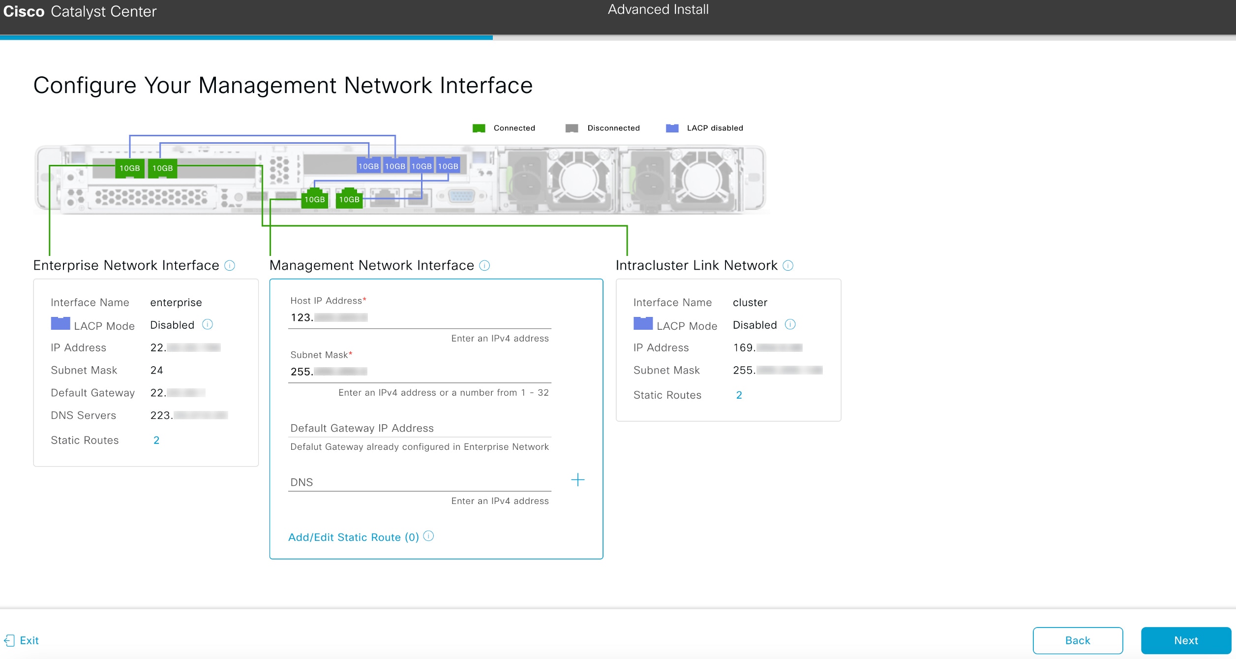
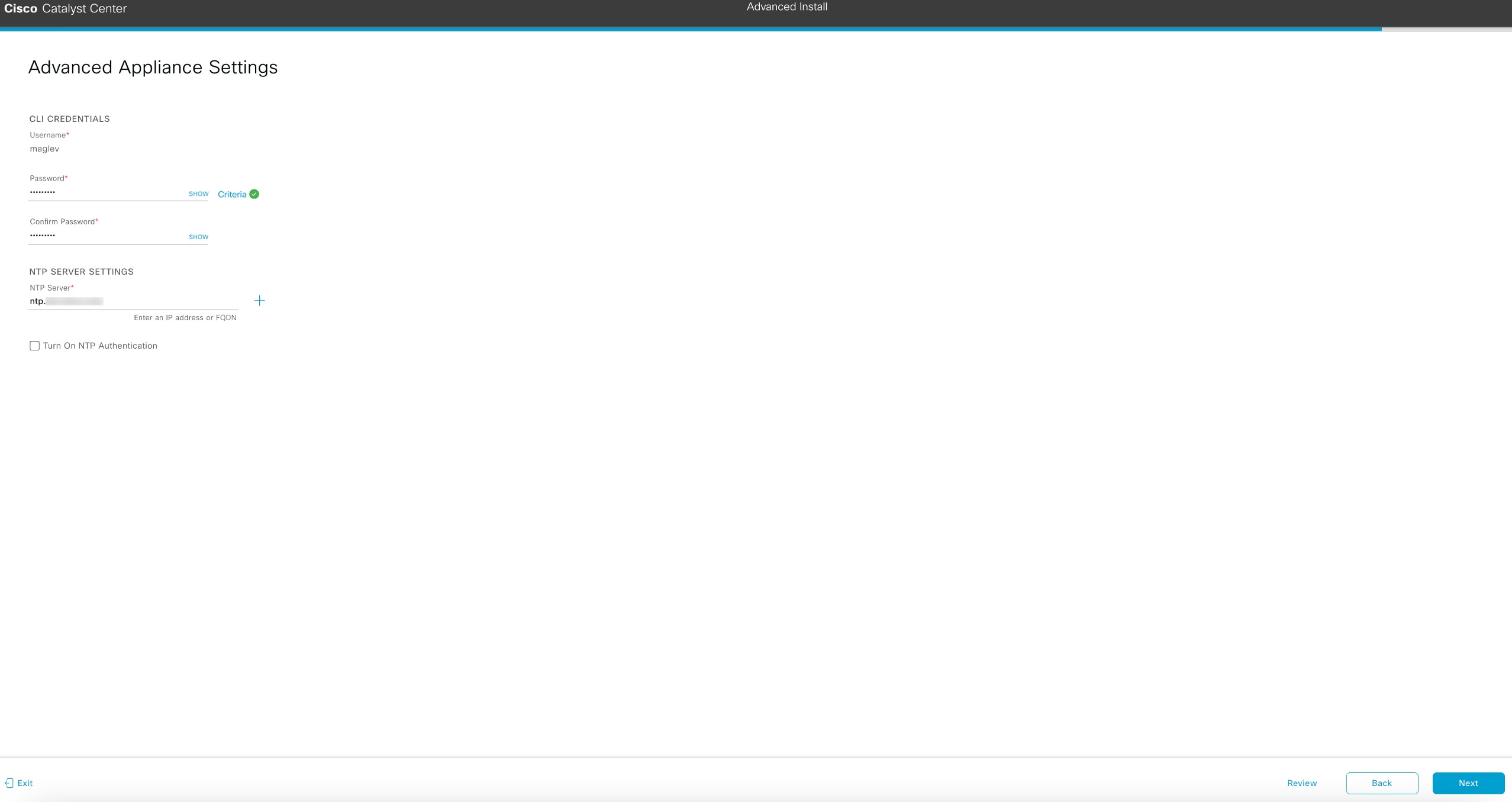
Advanced Install configuration wizard
This wizard provides access to all of the available appliance settings that you can modify. Use this wizard to specify interface settings that differ from the default or to configure the second or third node in your cluster..
Browser-based wizard prerequisites
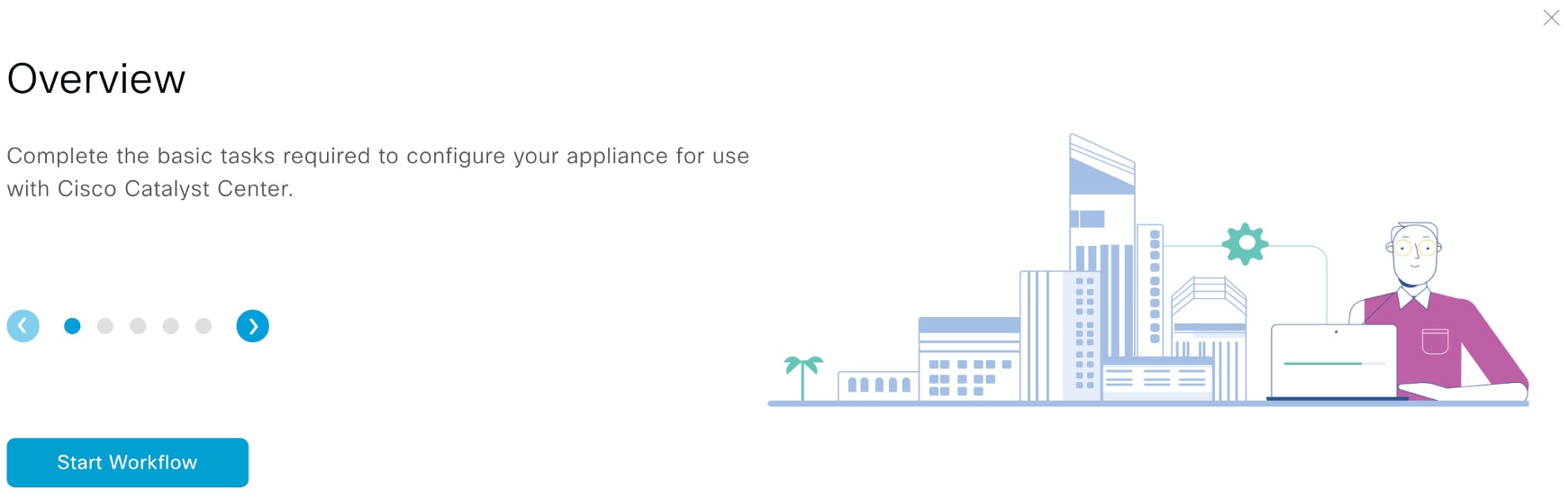
To properly configure your appliance using either of the browser-based wizards, complete these tasks:
-
Designate the enterprise interface on your appliance to use the IP address, subnet mask, and default gateway assigned by a DHCP server. The wizard does not allow changes to the assigned IP address or subnet mask, but allows you to change the default gateway. The assumption in this chapter is that the enterprise interface was selected for this purpose.
-
Ensure that the IP address assigned by the DHCP server is reachable by the machine from which you will complete the wizard.
-
Verify that both the enterprise and intracluster interfaces are connected and in the UP state.
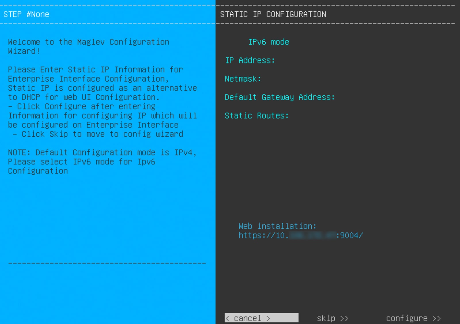
Alternatively, specify your own IP address, subnet mask, and default gateway for the enterprise interface of your appliance by completing the Static IP Address Settings page.
Password considerations
Refer to these topics for a description of the changes made to Catalyst Center's implementation of passwords.
VLAN mode considerations
Consider these details about VLAN mode:
-
For a description of VLAN mode, see Steps 7 and 8 in Configure the primary node using the Maglev wizard.
-
VLAN mode:
-
Can only be enabled when you configure a Catalyst Center appliance using the Maglev Configuration wizard.
-
Cannot be enabled using any of the browser-based configuration wizards.
-
Cannot be disabled without reimaging the appliance.
-
-
Disaster recovery is not supported by Catalyst Center deployments that have VLAN mode enabled.


 Feedback