|
Step 1
|
Start the Advanced Install configuration wizard:
-
Point your browser to the Cisco IMC IP address you set during the Cisco IMC GUI configuration you performed, then log in to
the Cisco IMC GUI as the Cisco IMC user (see Enable browser access to the Cisco Integrated Management Controller).
After successful login, the appliance displays the Cisco Integrated Management Controller Chassis Summary window, with a blue link menu at the upper right.
-
From the blue link menu, select and then select HTML based KVM.
The KVM console opens in a separate browser window or tab automatically. Use it to monitor the progress of the configuration
and respond to Maglev Configuration Wizard prompts.
-
With the KVM displayed, reboot the appliance by making one of these selections:
If asked to confirm your choice to reboot the appliance, click OK.
After displaying reboot messages, the KVM console displays the Static IP Configuration screen.
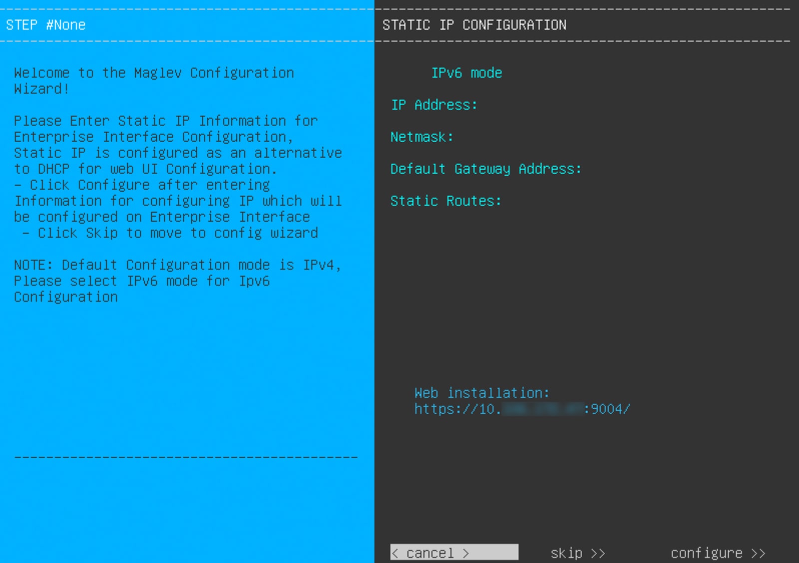 Record the URL listed in the Web Installation field.
-
Do one of these tasks:
-
If you want a DHCP server to assign an IP address, subnet mask, and default gateway to your appliance's Enterprise interface,
click Skip.
-
If you want to assign your own IP address, subnet mask, and default gateway to your appliance's Enterprise interface, enter
the information described in this table and then click Configure.
|
Note
|
You only need to specify an IP address, subnet mask, and default gateway for your appliance's Enterprise interface.
|
The KVM console displays the Maglev Configuration wizard welcome screen. 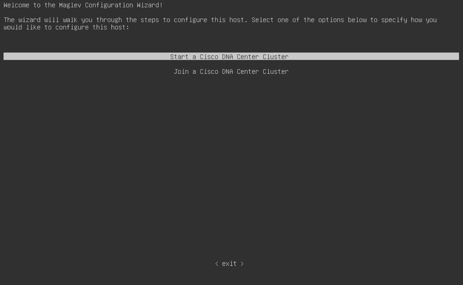
-
To bring up the Appliance Configuration screen, open the URL that was displayed in the Static IP Configuration screen.
-
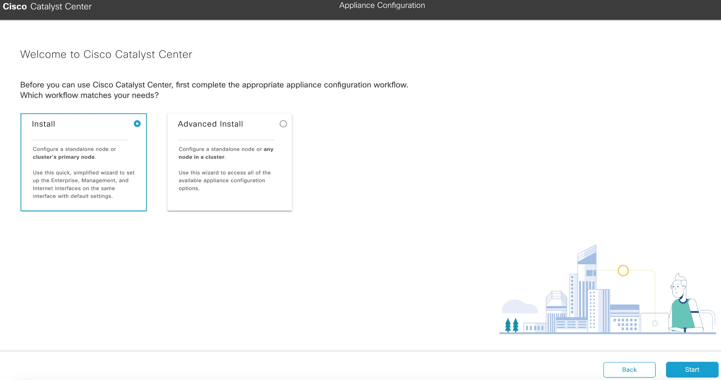
Click the Start a Cisco Catalyst Center Cluster radio button, then click Next.
-
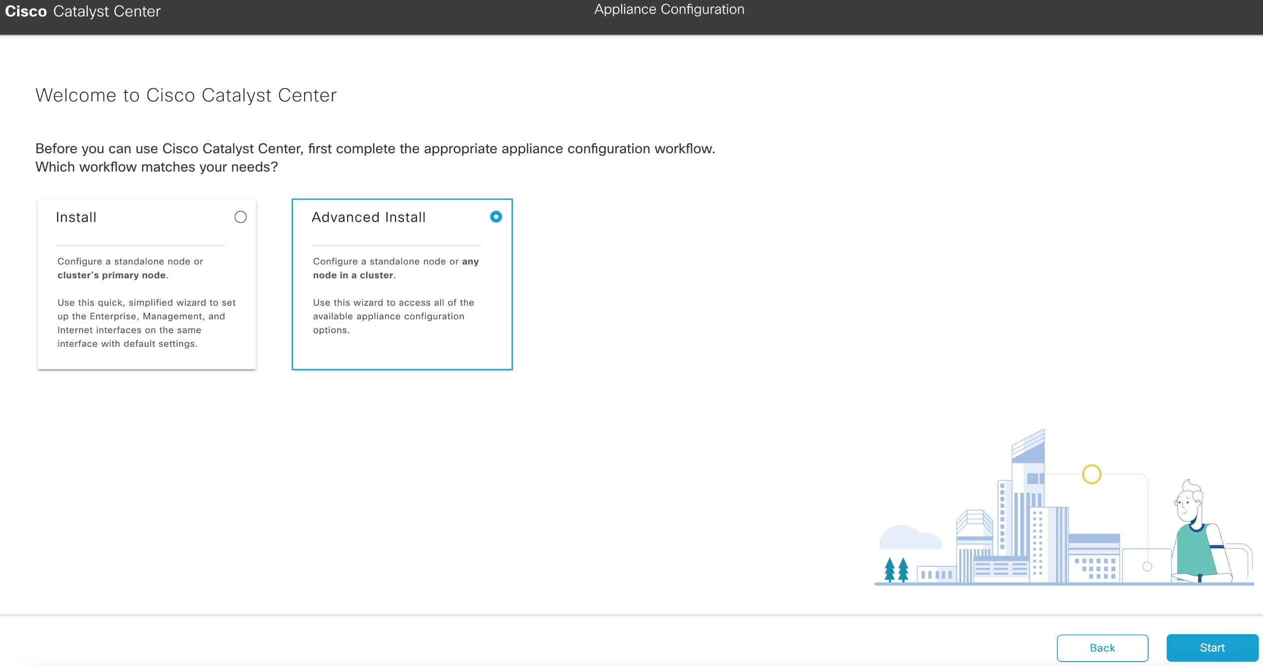
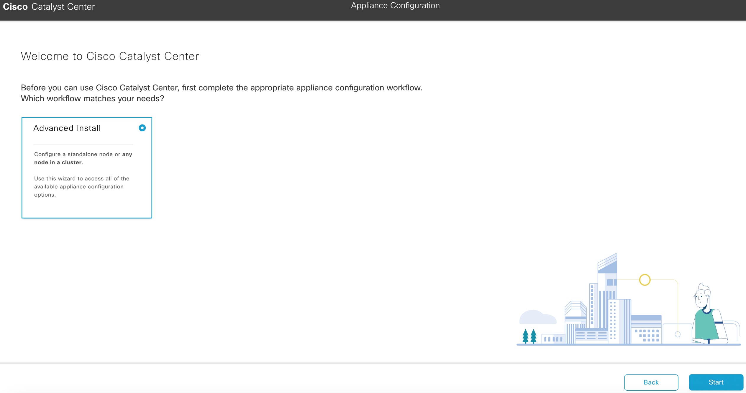
Click the Advanced Install radio button, then click Start.
The Overview slider opens. Click > to view a summary of the tasks that the wizard will help you complete.

-
Click Start Workflow to start the wizard.
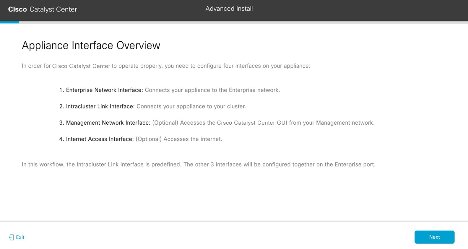
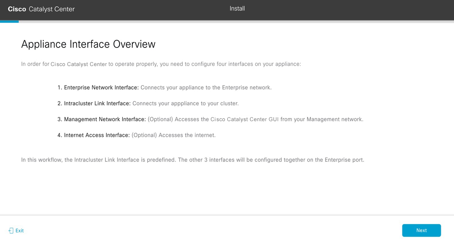
The Appliance Interface Overview screen opens, providing a description of the four appliance interfaces that you can configure.
|
Important
|
At a minimum, you must configure the Enterprise and Intracluster ports, as they are required for Catalyst Center functionality. If the wizard fails to display either or both of these ports during the course of configuration, they may
be non-functional or disabled. If you discover that the ports are non-functional, click Exit to close the wizard immediately. Verify that you have completed all of the steps provided in Execute preconfiguration tasks before resuming configuration or contacting the Cisco Technical Assistance Center (TAC).
|
|
|
Step 2
|
Complete the Advanced Install configuration wizard:
-
Click Next.
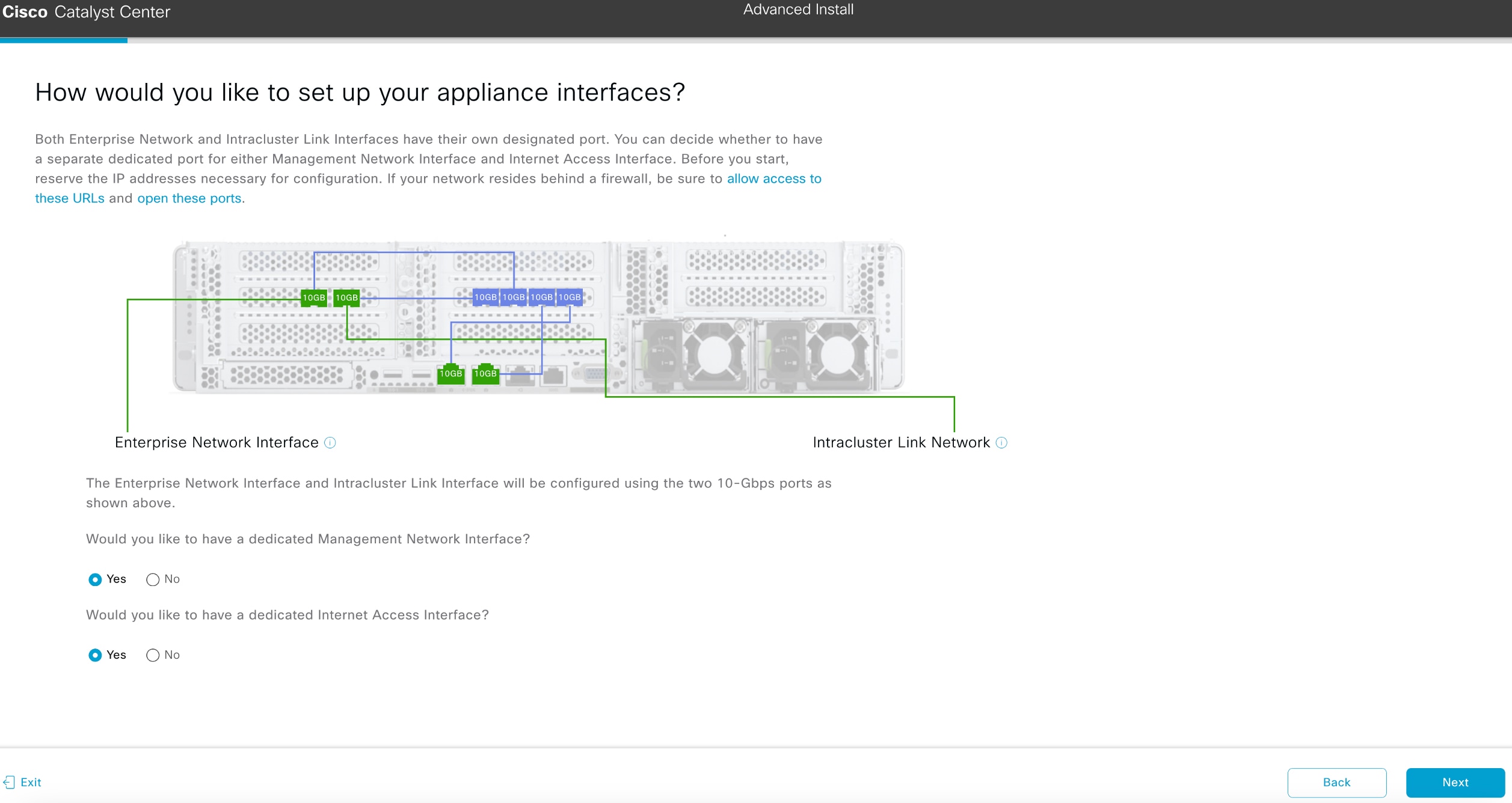
The How would you like to set up your appliance interfaces? screen opens.
 If your network resides behind a firewall, do these tasks:
-
Click the allow access to these URLs link to view a pop-up window that lists the URLs that Catalyst Center must be able to access.
-
Click the open these ports link to view a pop-up window that lists the network service ports that must be available for Catalyst Center to use.
-
Indicate whether you want to configure dedicated Management and Internet Access interfaces, then click Next.
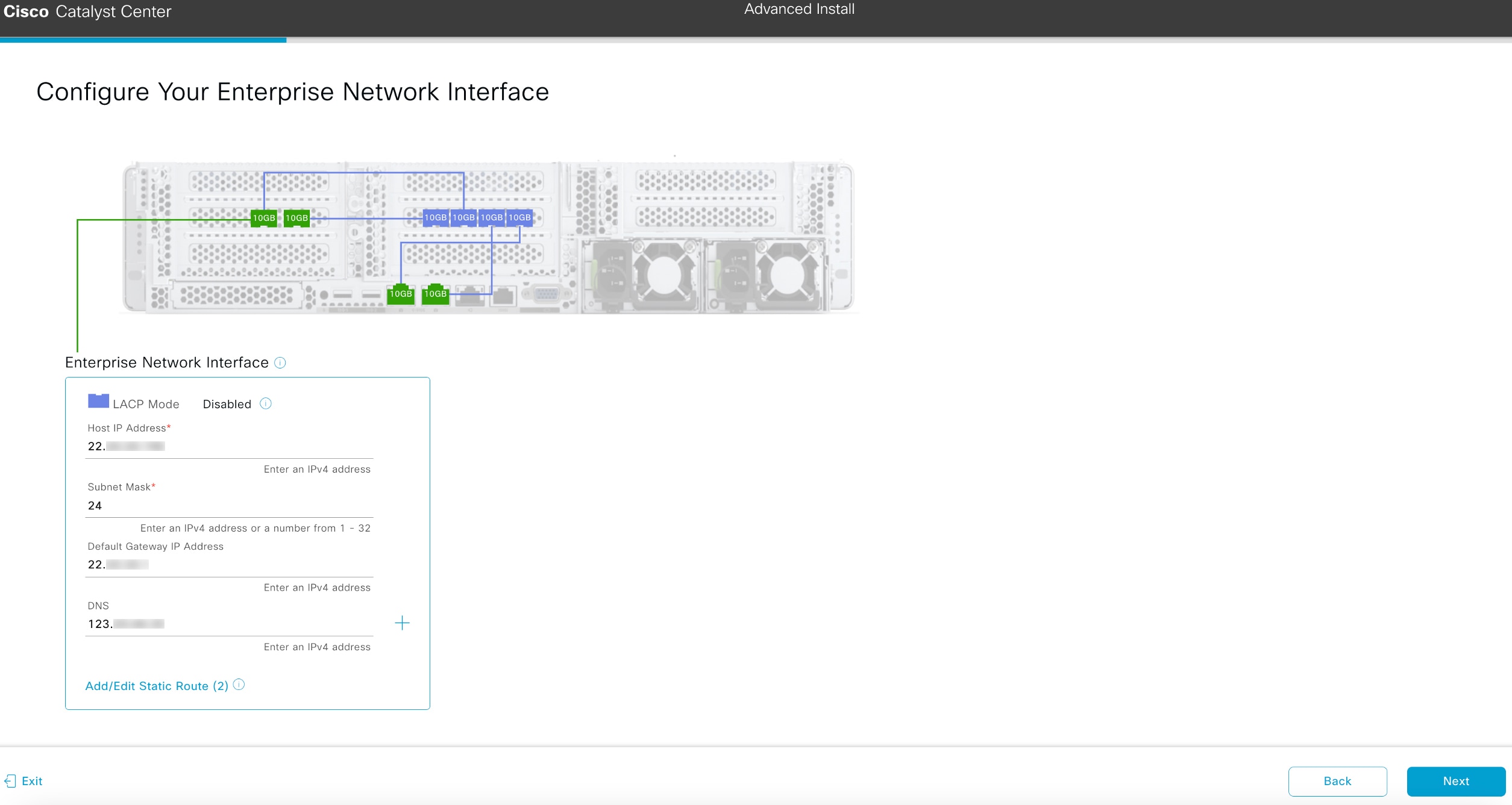
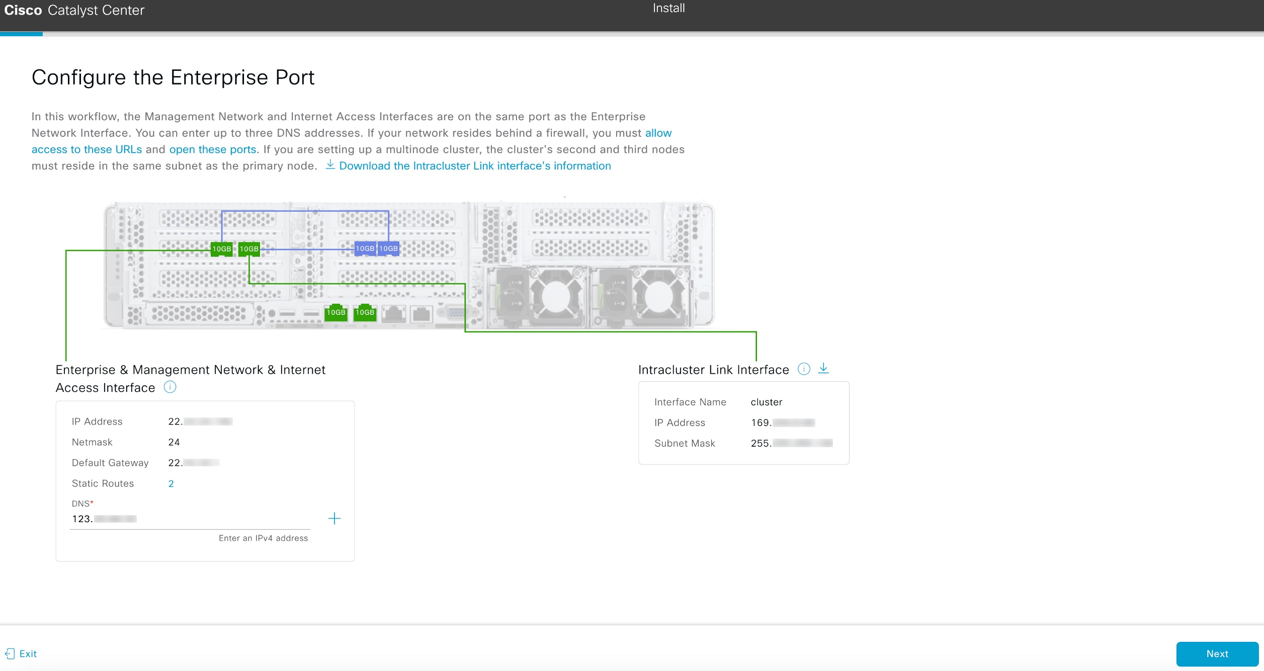
The Configure Your Enterprise Network Interface screen opens.
-
Enter configuration values for the enterprise interface, then click Next.
As explained in Interface cable connections, this is a required interface used to link the appliance to the enterprise network. See Required IP addresses and subnets and Required configuration information for a more detailed description of the values you need to enter.
The wizard validates the information you have entered, confirms that the port is up, and notifies you of any settings that
need to be changed before you can continue with the wizard. If the settings you have entered are valid and the port is up,
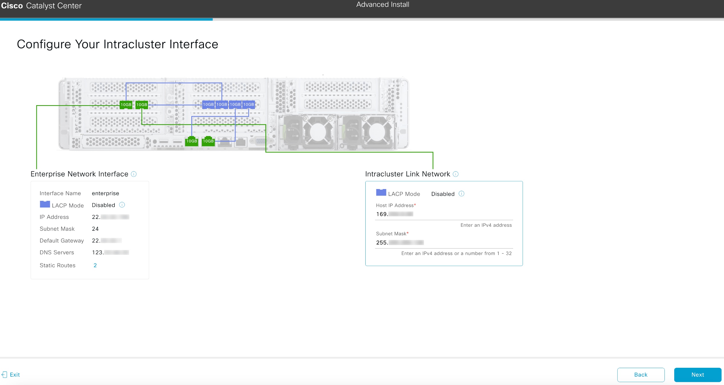
the Configure Your Intracluster Interface screen of the wizard opens.

-
Enter configuration values for your Intracluster interface, then click Next.
As explained in Interface cable connections, this required port is used to link the appliance to your cluster. See Required IP addresses and subnets and Required configuration information for a more detailed description of the values you need to enter.
|
Note
|
-
If you opted to configure the Enterprise and Internet Access interfaces on the same port, complete this step and then continue
to configuring the Management interface in Step 2e.
-
If you opted to configure the Enterprise and Management interfaces on the same port, complete this step and then continue
to configure your Internet Access interface in Step 2f .
-
If you opted to configure the Enterprise, Management, and Internet Access interfaces on the same port, complete this step
and then continue to Step 2g.
|
The wizard validates the information you have entered, confirms that the port is up, and notifies you of any settings that
need to be changed before you can continue with the wizard. If the settings you have entered are valid and the port is up,
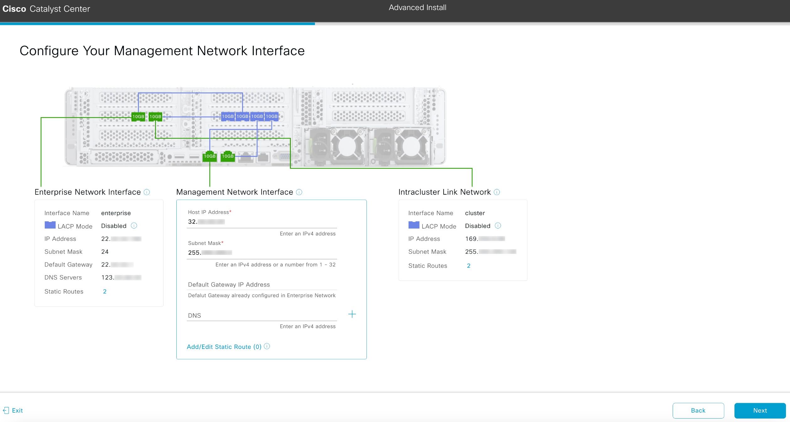
the wizard's Configure Your Management Network Interface screen opens.

-
(Optional) Enter configuration values for the Management interface, then click Next.
As explained in Interface cable connections, this port is used to access the Catalyst Center GUI from your management network. If you chose to configure a dedicated Management interface, enter the information described
in this table. (See Required IP addresses and subnets and Required configuration information for a more detailed description of the values you need to enter.)
|
Note
|
If you opted to configure the Enterprise and Internet Access interfaces on the same port, complete this step and then skip
ahead to Step 2g.
|
The wizard validates the information you have entered, confirms that the port is up, and notifies you of any settings that
need to be changed before you can continue with the wizard. If the settings you have entered are valid and the port is up,
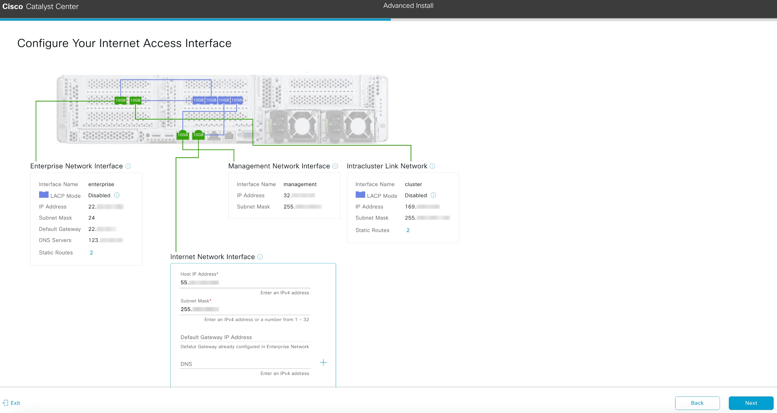
the wizard's Configure Your Internet Access Interface screen opens.

-
(Optional) Enter configuration values for the Internet Access interface, then click Next.
As explained in Interface cable connections, this is an optional port used to link the appliance to the Internet when you cannot do so through the Enterprise port. If
you chose to configure a dedicated Internet Access interface, enter the information described in this table. (See Required IP addresses and subnets and Required configuration information for a more detailed description of the values you need to enter.)
The wizard validates the information you have entered, confirms that the port is up, and notifies you of any settings that
need to be changed before you can continue with the wizard. If the settings you have entered are valid and the port is up,
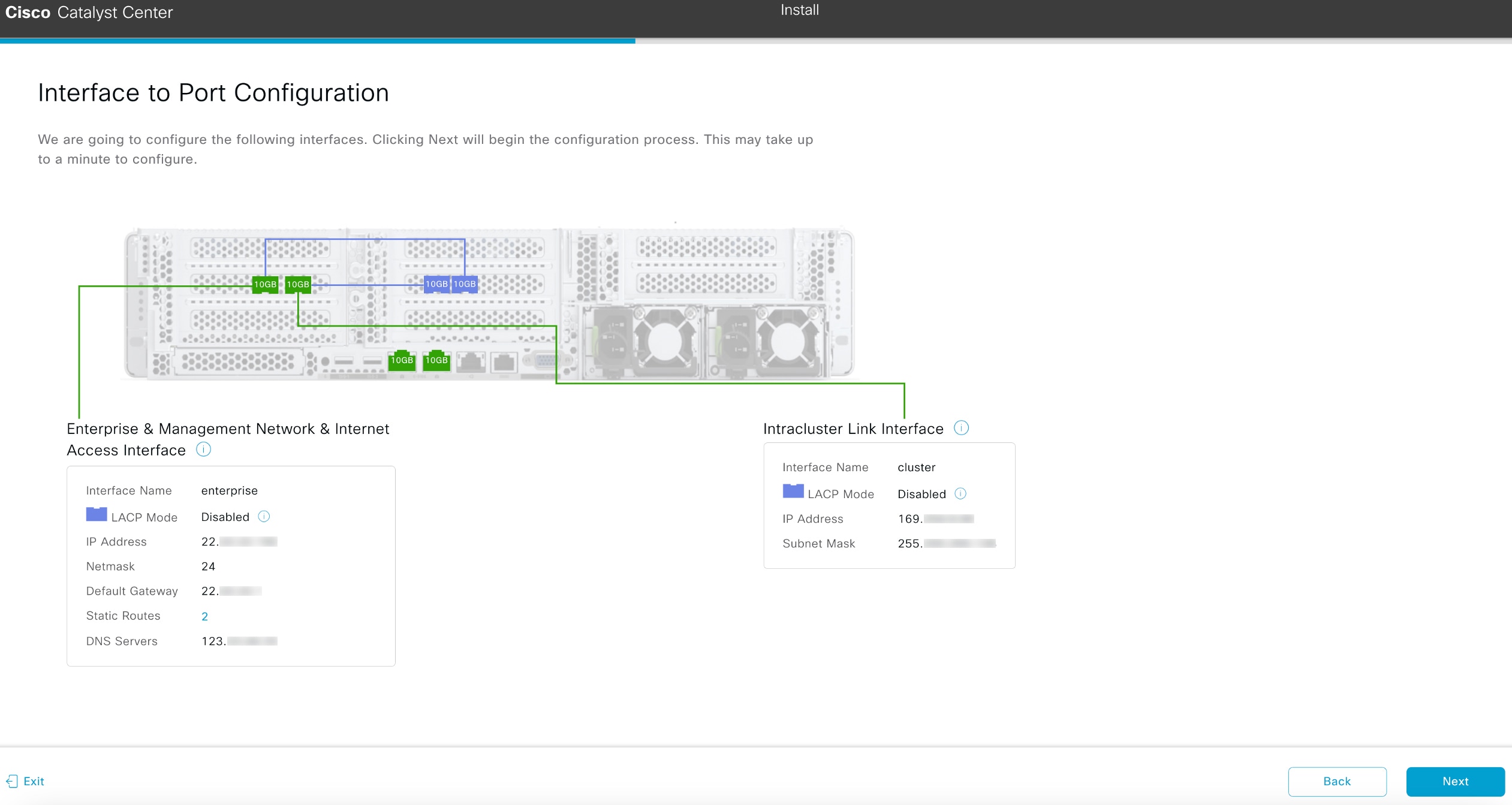
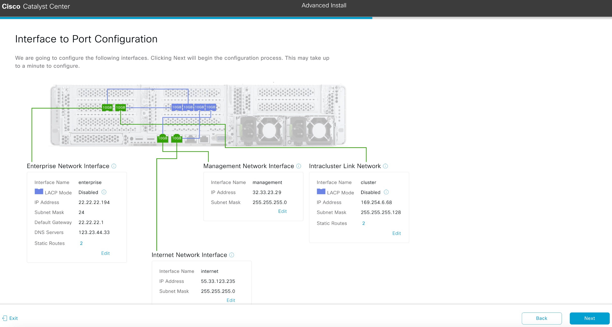
the wizard's Interface to Port Configuration screen opens.

-
Review the settings that you have entered for the primary node's interfaces.
If you need to make any changes, click the Edit link for the relevant interface.
-
After verifying that the interface settings are correct, click Next.
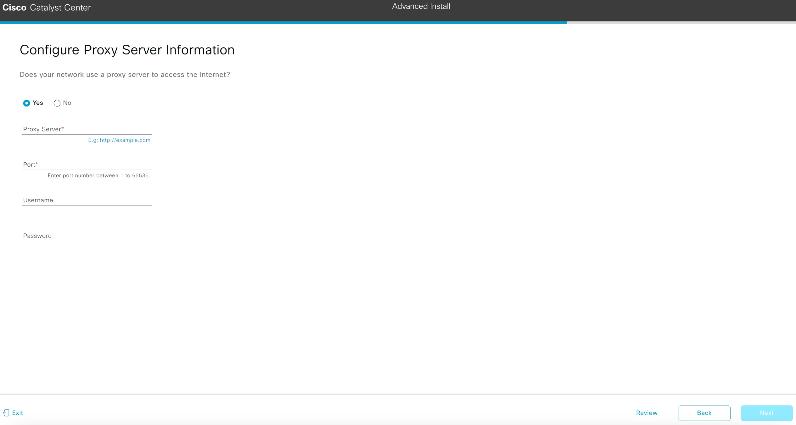
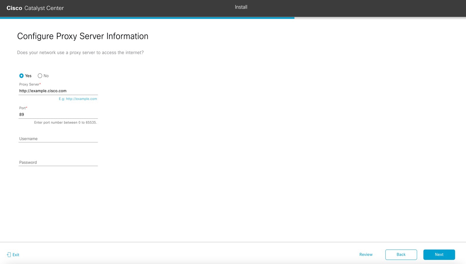
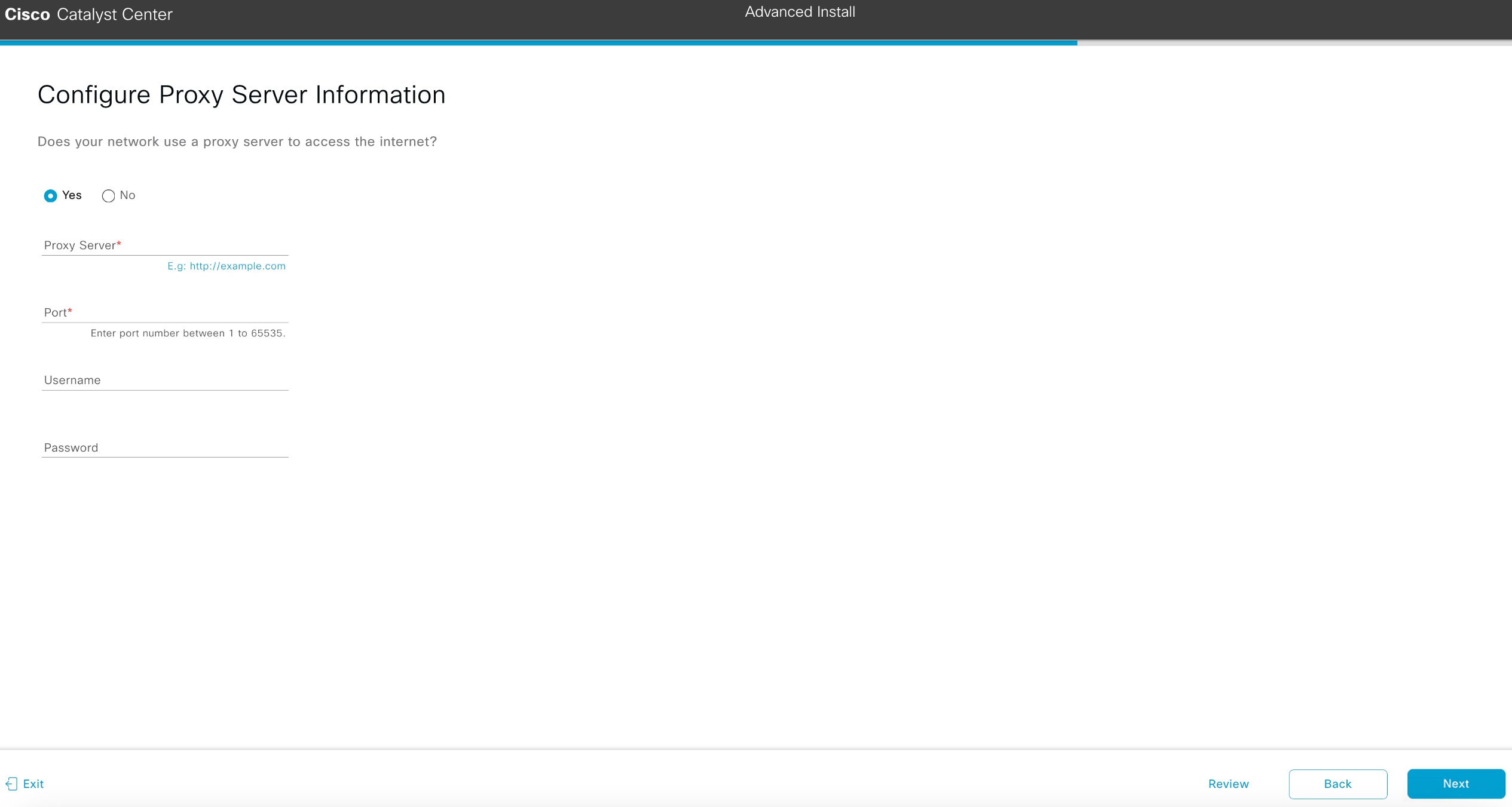
After initial interface configuration has completed, the Configure Proxy Server Information screen opens.
-
Do one of these tasks and then click Next:
-
If your network does not use a proxy server to access the internet, click the No radio button.
-
If your network does use a proxy server to access the internet, enter the values described in this table:
Table 7. Primary node entries for proxy server settings
|
Proxy Server field
|
Enter the URL or host name of an HTTPS network proxy used to access the Internet.
|
Note
|
Connection from Catalyst Center to the HTTPS proxy is supported only via HTTP in this release.
|
|
|
Port field
|
Enter the port your appliance used to access the network proxy.
|
|
Username field
|
Enter the user name used to access the network proxy. If no proxy login is required, leave this field blank.
|
|
Password field
|
Enter the password used to access the network proxy. If no proxy login is required, leave this field blank.
|
The wizard validates the information you have entered and notifies you of any settings that need to be changed before you
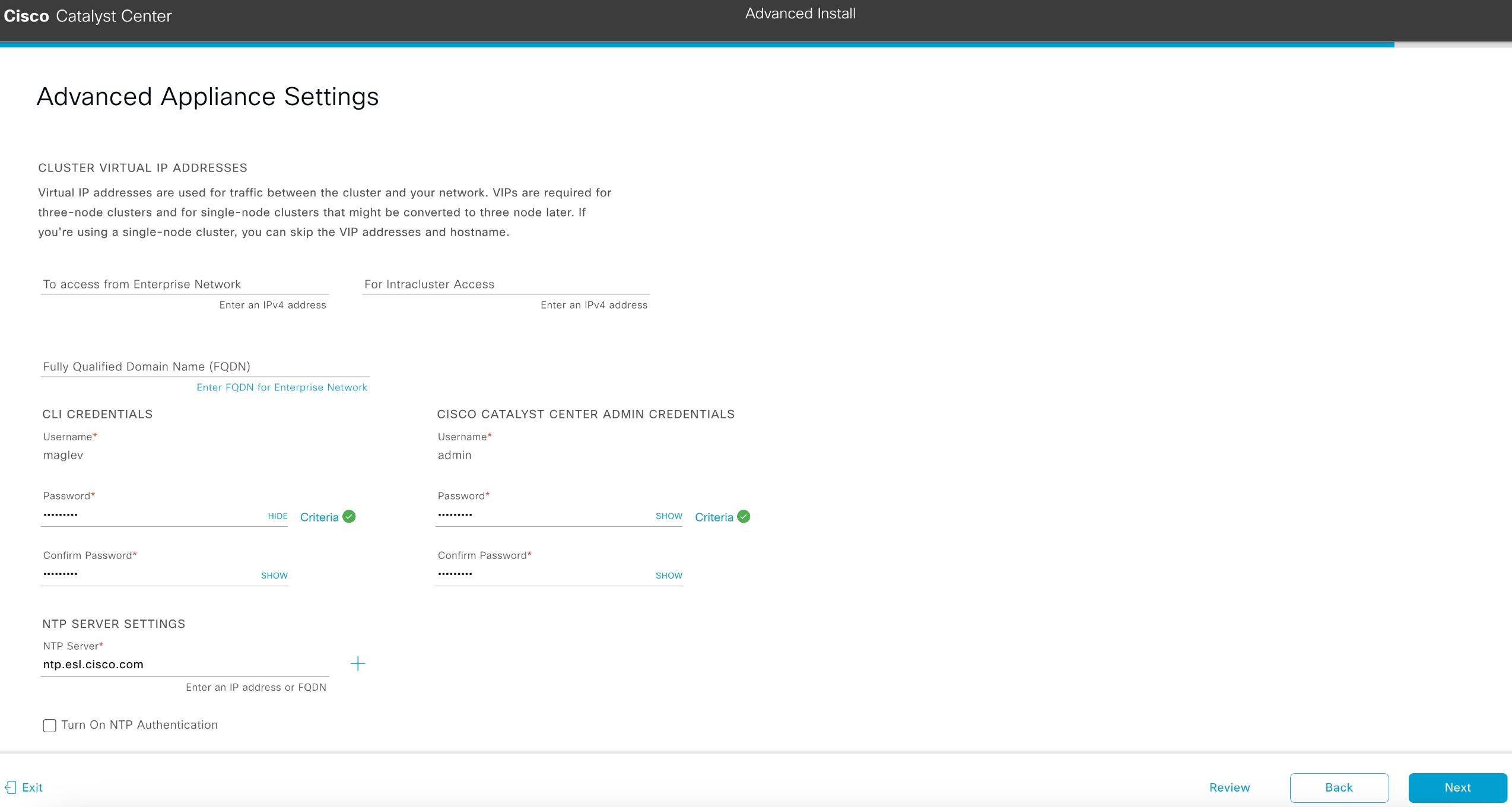
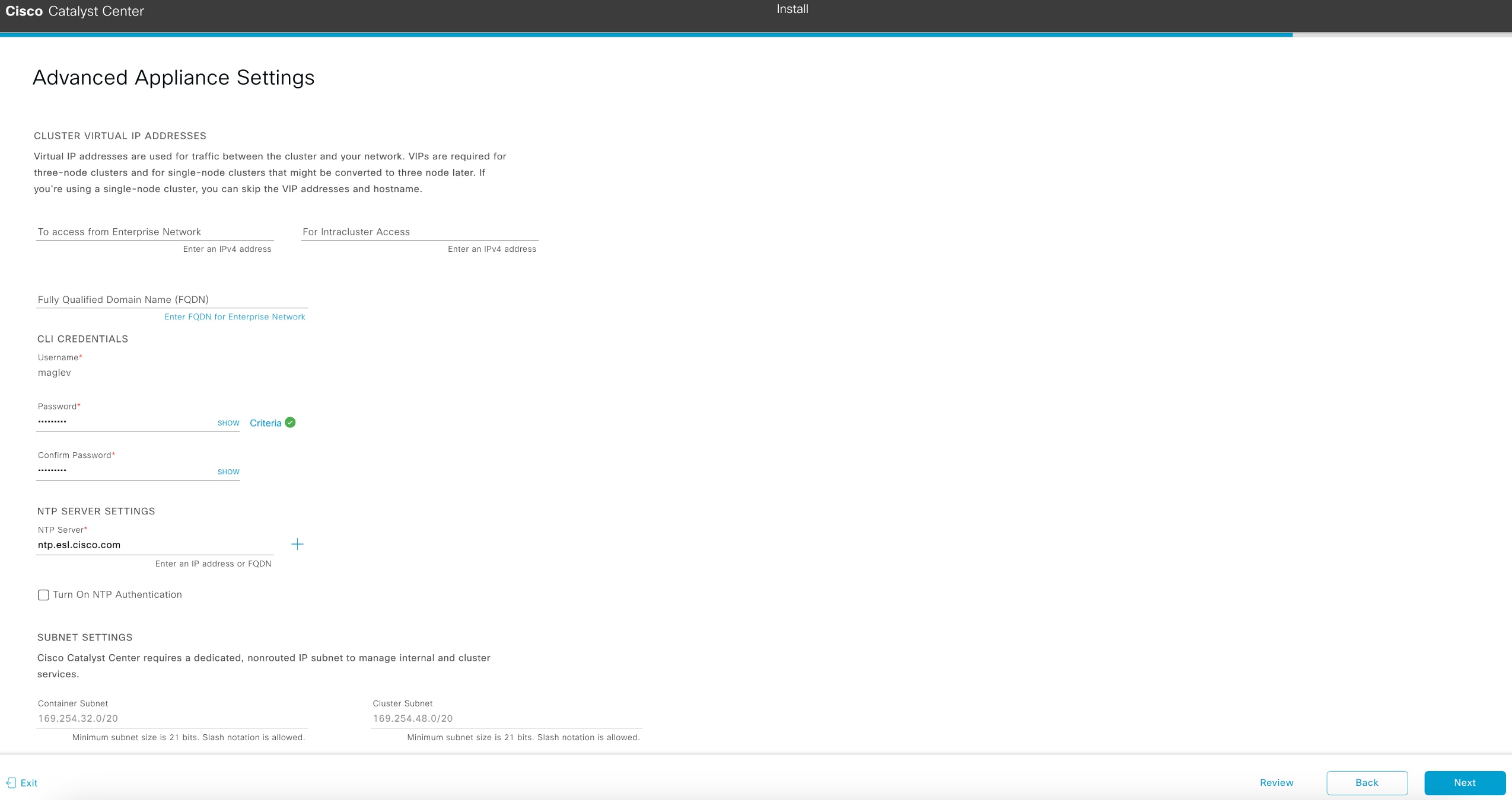
can continue with the wizard. If the settings you have entered are valid and the port is up, the wizard's Advanced Appliance Settings screen opens.
-
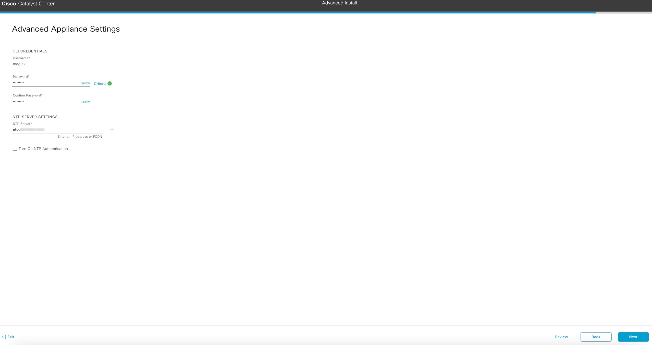
Enter configuration values for your cluster, then click Next.
Table 8. Primary node entries for advanced appliance settings
|
Cluster virtual IP addresses
|
|
To access from enterprise network, for intracluster access, to access from management network, and for internet access fields
|
Note
|
If you configured the management or internet access interface on the same port as the enterprise interface, its corresponding
field is not displayed in this section.
|
|
Enter the virtual IP address that will be used for traffic between the cluster and the interfaces that you have configured
on your primary node. This is required for both three-node clusters and single-node clusters that will be converted into a
three-node cluster in the future. If you have a single-node cluster setup and don't plan to move to a three-node cluster setup,
you can leave the fields in this section blank.
|
Important
|
If you decide to configure a virtual IP address, you must enter one for each configured network interface. You will not be
able to complete the wizard unless you do so. These addresses are tied to the cluster link's status, which must be in the
UP state.
|
|
|
Fully Qualified Domain Name (FQDN) field
|
Enter the fully qualified domain name (FQDN) for your cluster. Catalyst Center does these tasks with this hostname:
-
It uses this hostname to access your cluster’s web interface and the Representational State Transfer (REST) APIs used by devices
thatCatalyst Center manages in the enterprise network.
-
In the Subject Alternative Name (SAN) field of Catalyst Center certificates, it uses the FQDN to the define the Plug and Play server that should be used for device provisioning.
|
|
CLI credentials
Enter and confirm the password for the maglev user.
|
|
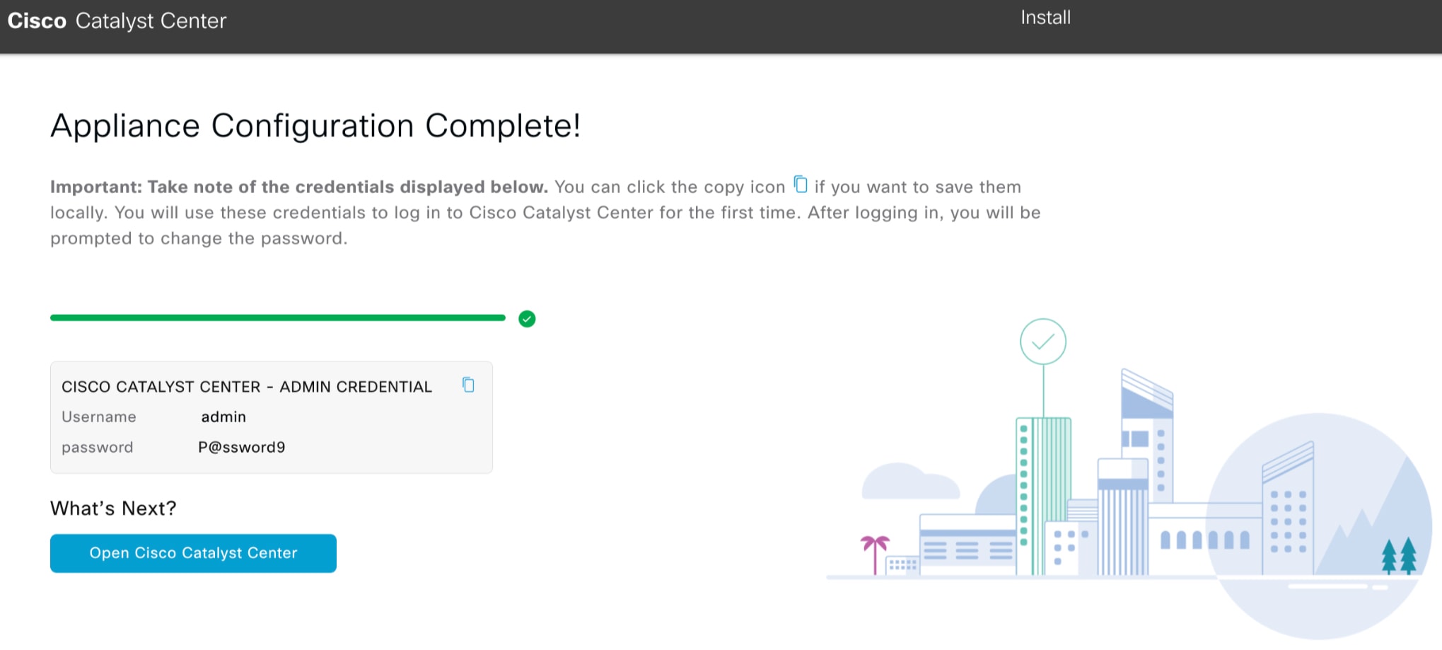
Cisco Catalyst Center admin credentials
Enter a password for the default admin superuser, used to log in to Catalyst Center for the first time.
|
|
NTP server settings
|
|
NTP Server field
|
Enter at least one NTP server address or hostname. To enter additional NTP server addresses or hostnames, click the Add (+) icon.
For a production deployment, Cisco recommends that you configure a minimum of three NTP servers.
|
|
Turn on NTP Authentication check box
|
To enable the authentication of your NTP server before it's synchronized with Catalyst Center, check this check box and then enter this information:
-
The NTP server's key ID. Valid values range between 1 and 4294967295 (2^32-1).
This value corresponds to the key ID that's defined in the NTP server's key file.
-
The SHA-1 key value associated with the NTP server's key ID. This 40-character hex string resides in the NTP server's key
file.
|
Note
|
Ensure that you enter a key ID and key value for each NTP server that you configured in the previous field.
|
|
|
Subnet settings
|
|
Container Subnet field
|
A dedicated, non-routed IP subnet that Catalyst Center uses to manage internal services. By default, this is already set to 169.254.32.0/20, and we recommend that you use this subnet.
|
|
Cluster Subnet field
|
A dedicated, non-routed IP subnet that Catalyst Center uses to manage internal cluster services. By default, this is already set to 169.254.48.0/20, and we recommend that you use this subnet.
|
The wizard validates the information you have entered and notifies you of any settings that need to be changed before you
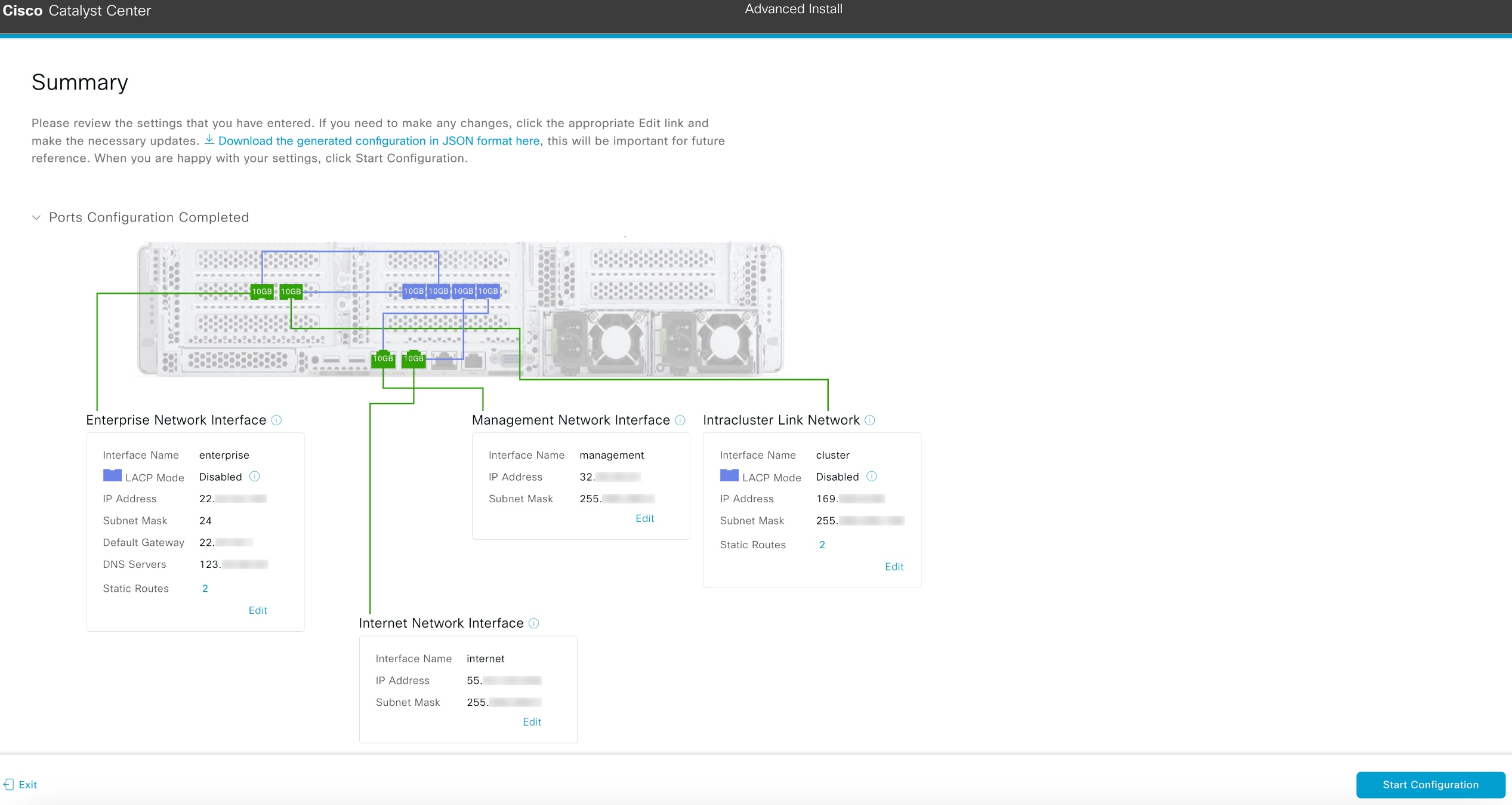
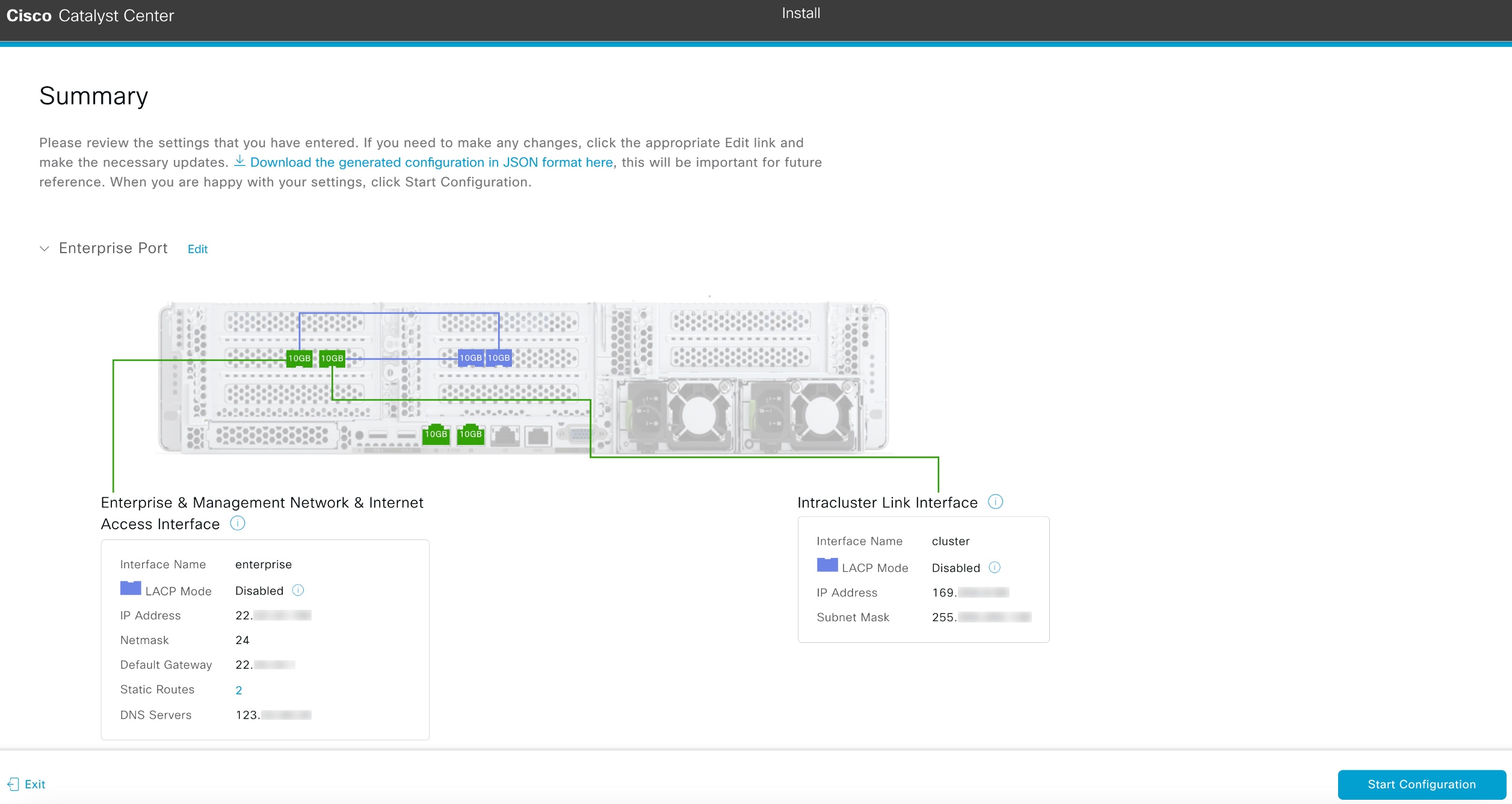
can continue with the wizard. If the settings you have entered are valid, the wizard's Summary screen opens.
|
Note
|
To download the appliance configuration as a JSON file, click the here link.
|
-
Review all of the settings that you have entered while completing the wizard. If you need to update settings, click the relevant
Edit link to open the corresponding wizard screen.
-
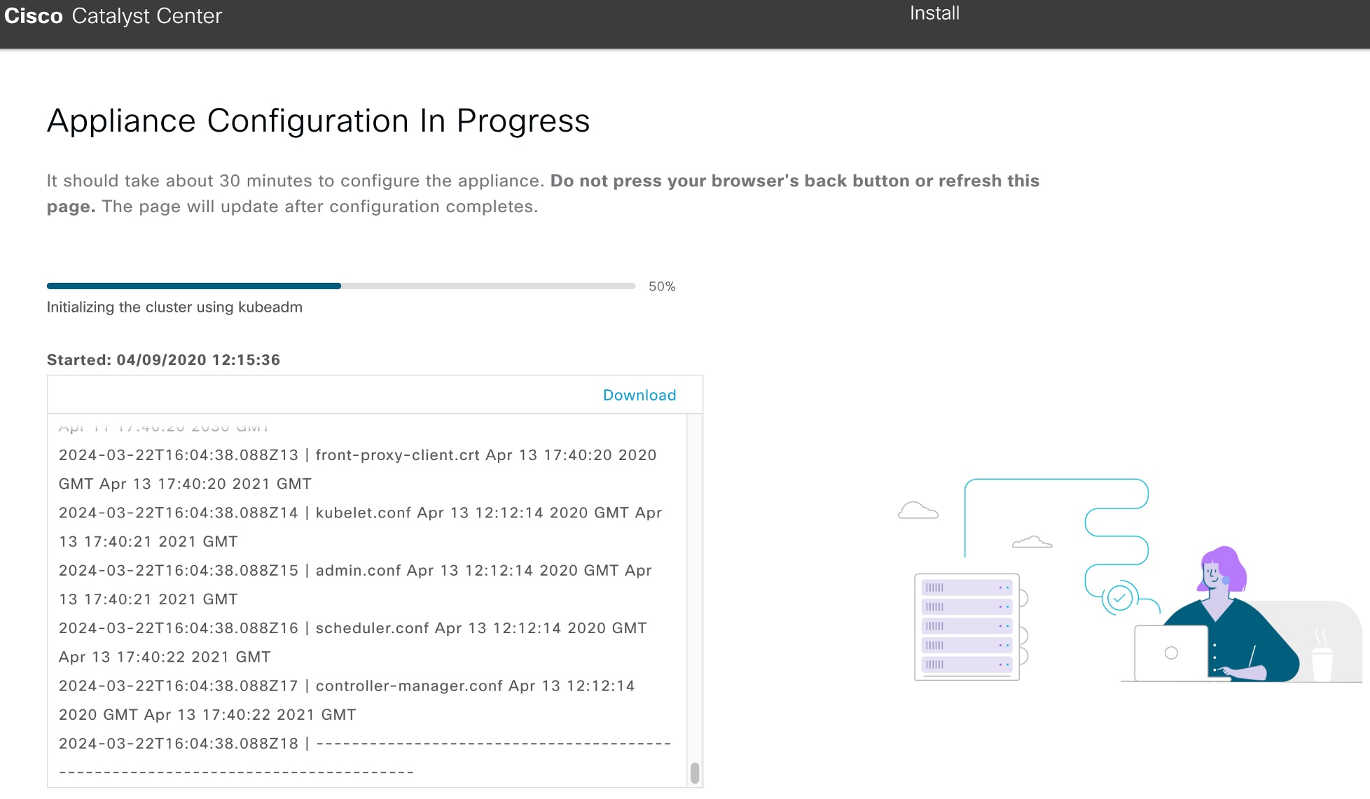
To complete the configuration of your Catalyst Center appliance, click Start Configuration.
The wizard screen continuously updates during the process, indicating the tasks that are currently being completed and their
progress, as well as any errors that have occurred. To save a local copy of this information as a text file, click the download
icon.

|


 ) and choosing
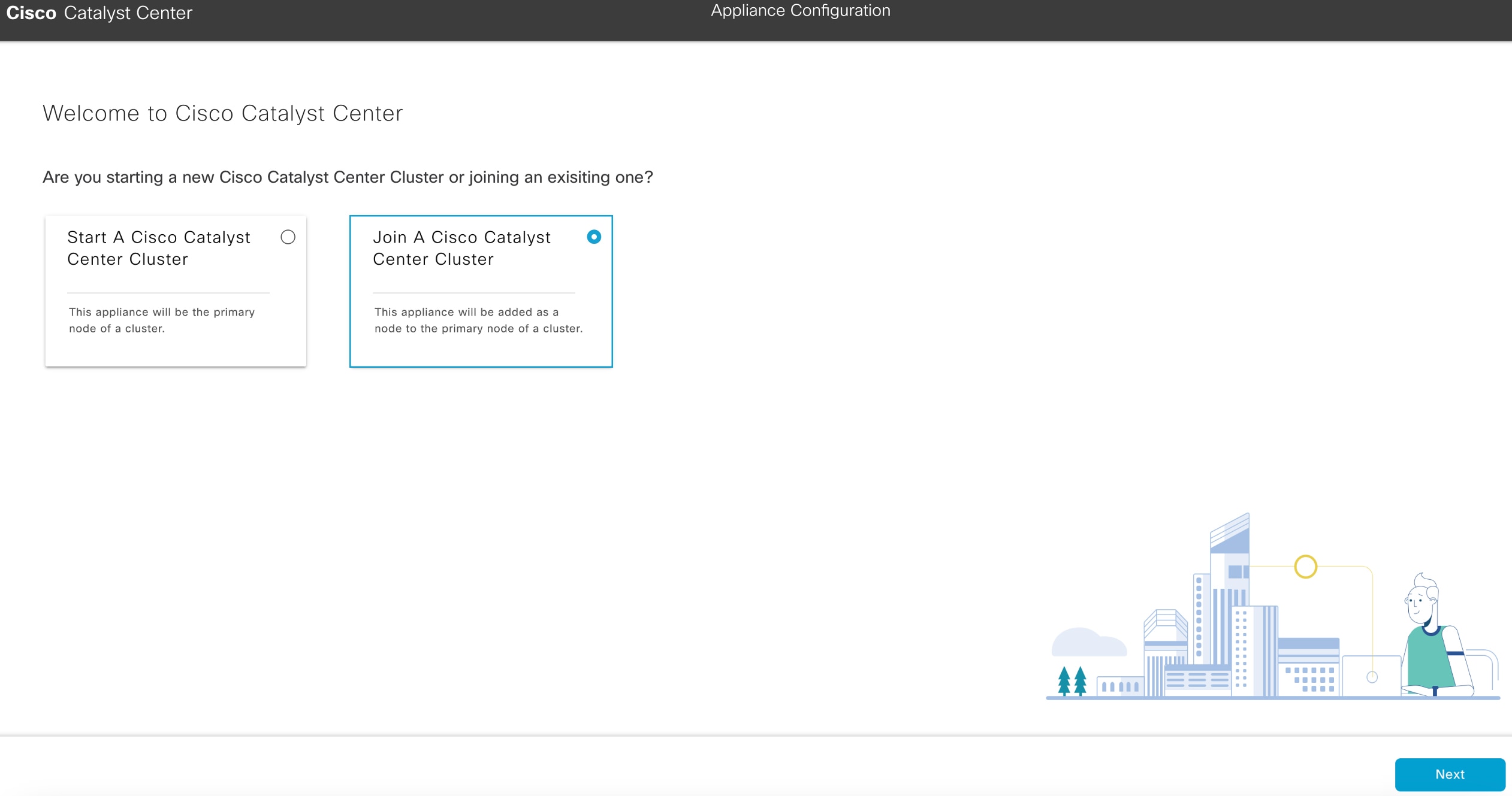


 Feedback