Appliance hardware specifications
Cisco provides Catalyst Center as a rack-mountable physical appliance with these hardware specifications.
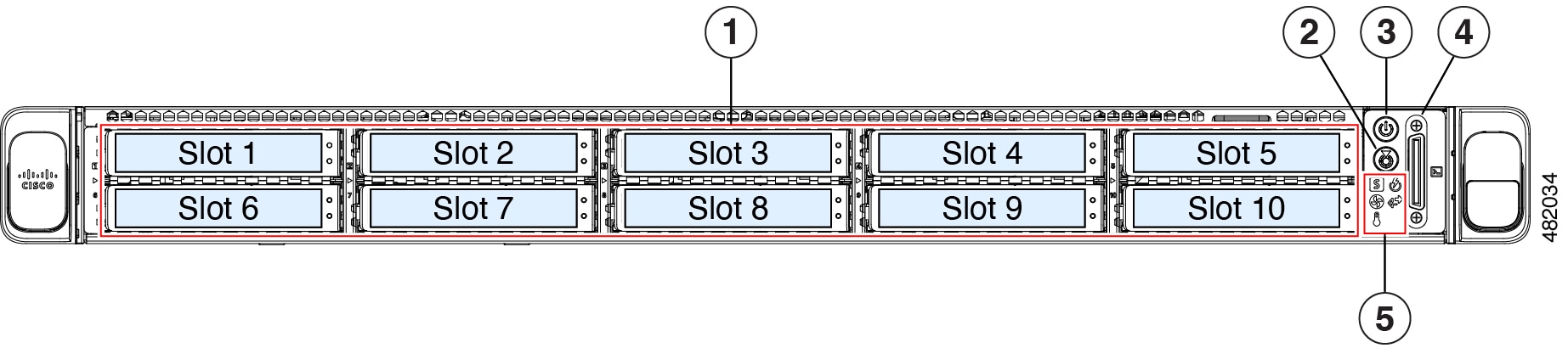
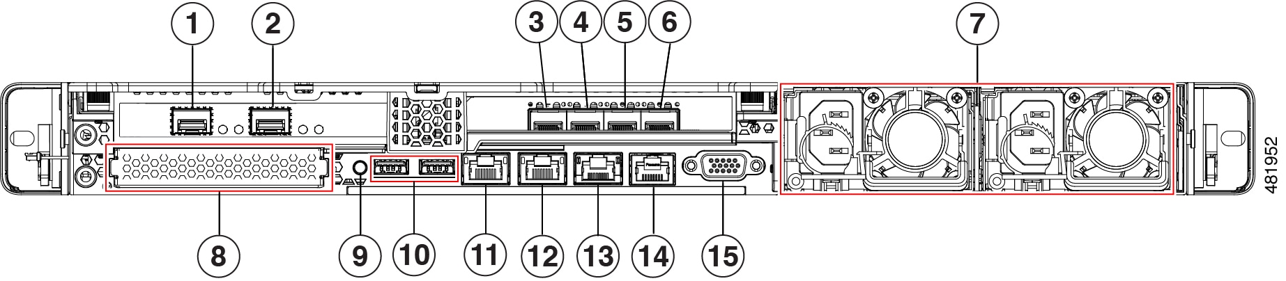
Medium Catalyst Center appliance
This table provides the hardware specifications for the third-generation medium Catalyst Center appliance.
|
Feature |
Description |
||
|---|---|---|---|
|
Cisco part number |
DN3-HW-APL |
||
|
Chassis |
One rack-unit (1RU) Cisco Unified Computing System (UCS) C220 M6 chassis |
||
|
Number of cores |
32 |
||
|
Processors |
Two Intel Xeon Gold 6326 processors. |
||
|
Memory |
Eight 32 GB DDR4 3200 MHz registered DIMMs (RDIMMs). |
||
|
Storage/Disk Management (RAID) |
Cisco RAID Controller with 4GB FBWC:
|
||
|
Network and management I/O |
Supported connectors:
These connectors are available but not typically used in the day-to-day operation of Catalyst Center:
|
||
|
Power |
Two 2300 W AC power supplies. 1 + 1 redundancy. |
||
|
Cooling |
Eight hot-swappable fan modules for front-to-rear cooling. |
||
|
Video |
The Cisco Integrated Management Controller (CIMC) provides video using the Matrox G200e video/graphics controller:
|
||
|
ACPI |
The advanced configuration and power interface (ACPI) 4.0 standard is supported. |
||
|
Integrated Management Processor |
Baseboard Management Controller (BMC) running Cisco Integrated Management Controller (Cisco IMC) firmware. Depending on the CIMC settings, you can access the CIMC through the 1GE dedicated management port, the 1GE/10GE LOM ports, or a Cisco virtual interface card (VIC). |
Large Catalyst Center appliance
This table summarizes the hardware specifications for the third-generation large Catalyst Center appliance.
|
Feature |
Description |
||
|---|---|---|---|
|
Cisco part number |
DN3-HW-APL-L |
||
|
Chassis |
1RU Cisco UCS C220 M6 chassis |
||
|
Number of cores |
56 |
||
|
Processors |
Two Intel Xeon Gold 6348 processors |
||
|
Memory |
Twelve 32 GB DDR4 3200 MHz RDIMMs |
||
|
Storage/Disk Management (RAID) |
Cisco RAID Controller with 4GB FBWC:
|
||
|
Network and management I/O |
Supported connectors:
These connectors are available but not typically used in the day-to-day operation of Catalyst Center:
|
||
|
Power |
Two 2300 W AC power supplies. Redundant as 1 + 1. |
||
|
Cooling |
Eight hot-swappable fan modules for front-to-rear cooling. |
||
|
Video |
Cisco IMC provides video using the Matrox G200e video and graphics controller:
|
||
|
ACPI |
The ACPI 4.0 standard is supported. |
||
|
Integrated Management Processor |
BMC running Cisco IMC firmware. Depending on your CIMC settings, the CIMC can be accessed through the 1GE dedicated management port, the 1GE/10GE LOM ports, or a Cisco VIC. |
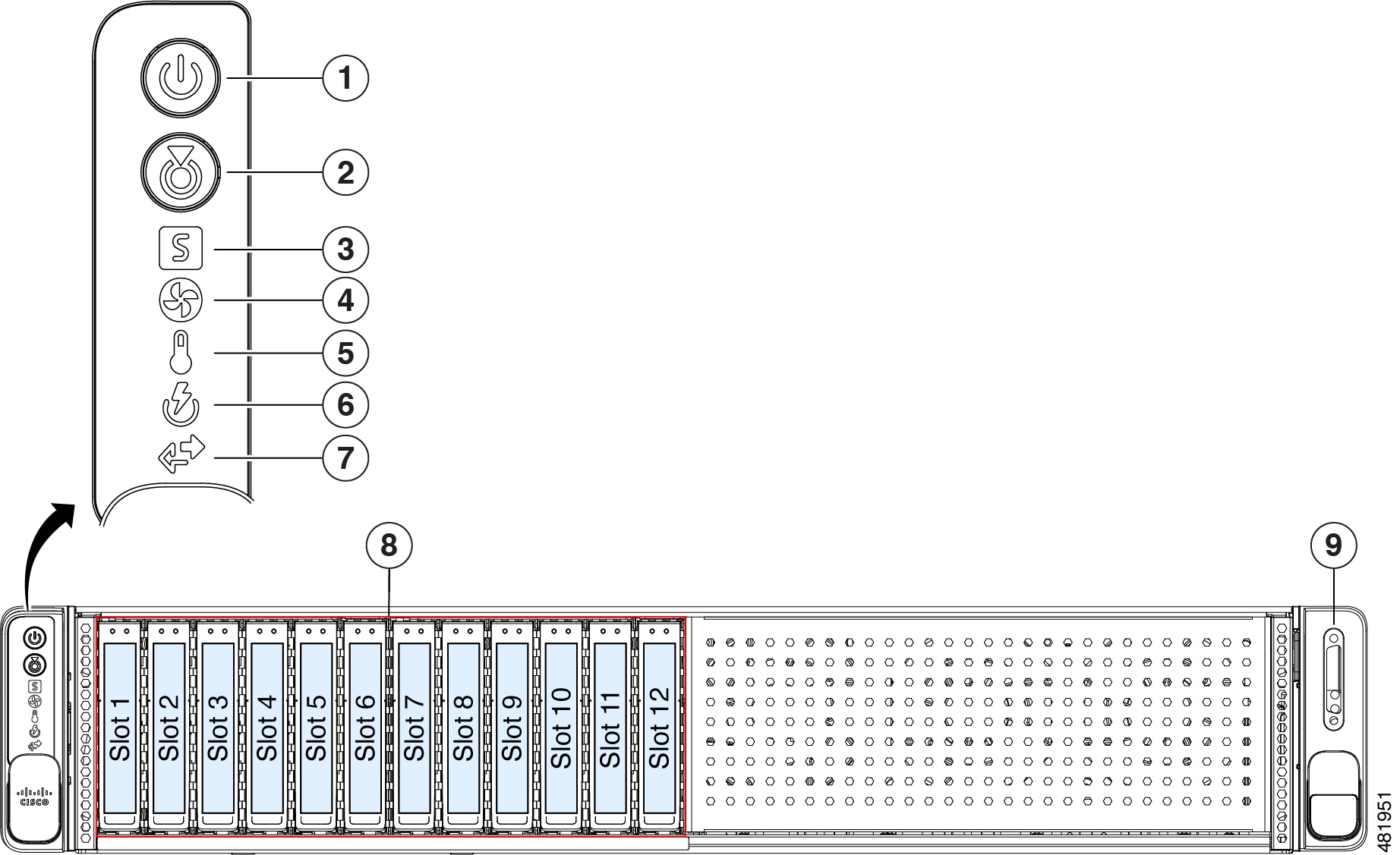
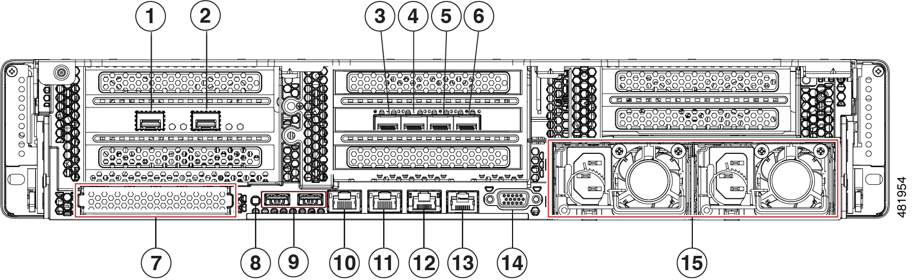
Extra large Catalyst Center appliance
This table provides the hardware specifications for the third-generation extra large Catalyst Center appliance.
|
Feature |
Description |
||
|---|---|---|---|
|
Cisco part number |
DN3-HW-APL-XL |
||
|
Chassis |
Two rack-unit (2RU) Cisco UCS C240 M6 chassis |
||
|
Number of cores |
80 |
||
|
Processors |
Two Intel Xeon Platinum 8380 processors |
||
|
Memory |
Twelve 64 GB DDR4 3200 MHz RDIMMs |
||
|
Storage/Disk Management (RAID) |
Cisco RAID Controller with 4GB FBWC:
|
||
|
Disk Management (RAID) |
Cisco RAID Controller with 4GB FBWC:
|
||
|
Network and management I/O |
Supported connectors:
These connectors are available but not typically used in the day-to-day operation of Catalyst Center:
|
||
|
Power |
Two 2300 W AC power supplies 1 + 1 redundancy |
||
|
Cooling |
Six hot-swappable fan modules for front-to-rear cooling. |
||
|
Video |
Cisco IMC provides video using the Matrox G200e video/graphics controller:
|
||
|
ACPI |
The ACPI 4.0 standard is supported. |
||
|
Integrated Management Processor |
BMC running Cisco IMC firmware. Depending on your CIMC settings, the CIMC can be accessed through the 1GE dedicated management port, the 1GE/10GE LOM ports, or a Cisco VIC. |

 Feedback