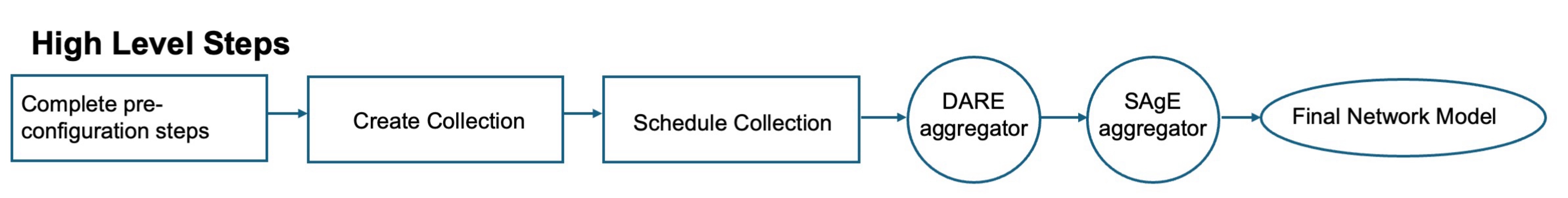
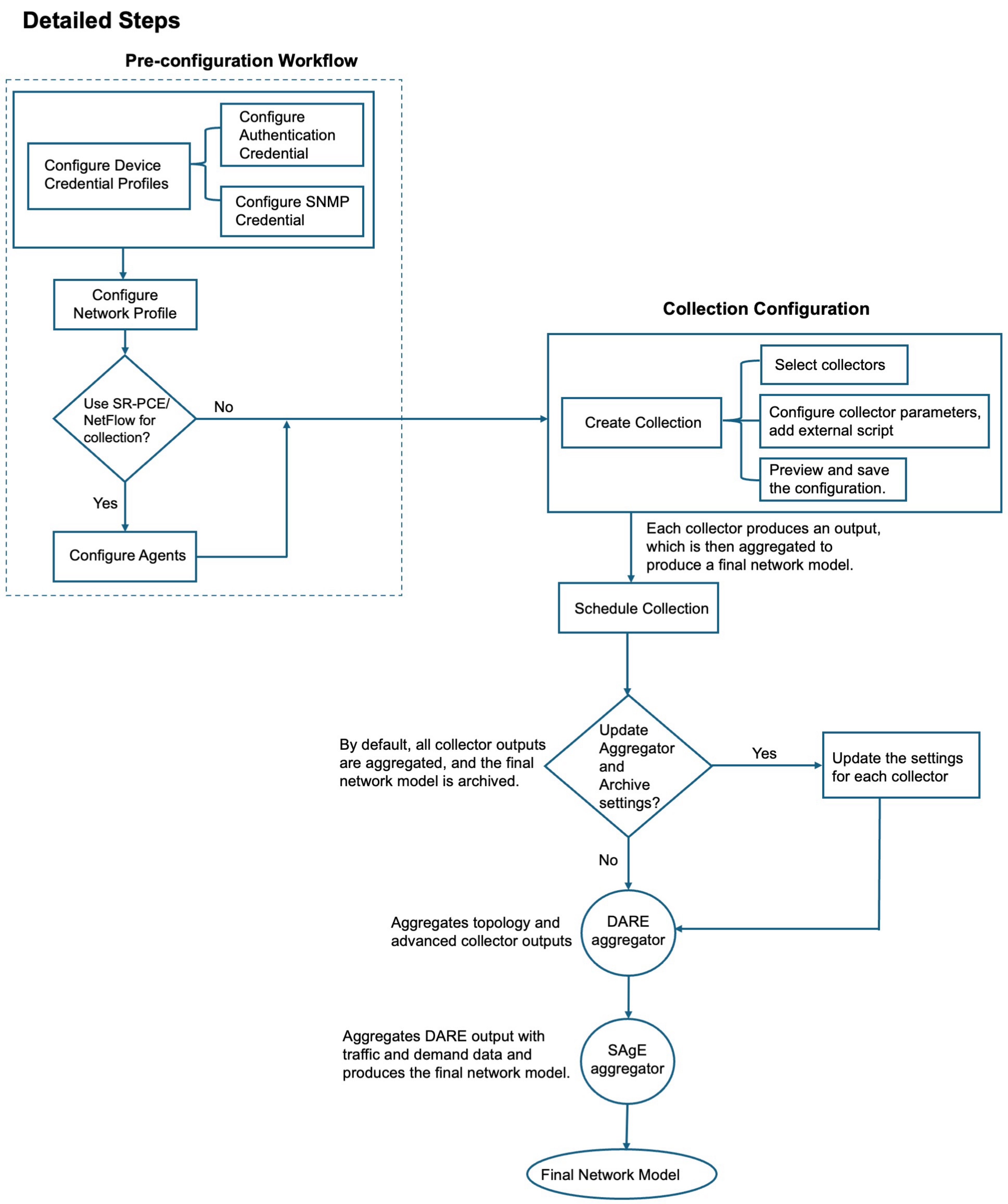
Network model creation workflow
The Cisco Crosswork Planning UI provides an easy-to-use interface that hides the complexity of creating a model building chain for a network. It combines the configuration of multiple data collectors under one network (collection) and can produce a single network model that contains the consolidated data. Use the Cisco Crosswork Planning UI for configuring device and network access, creating network models, managing users, and configuring agents.
The Table 1 and Network model creation workflow illustrate how you can configure individual network models.
|
Step |
Action |
|---|---|
|
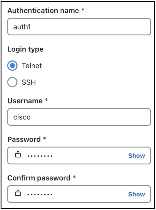
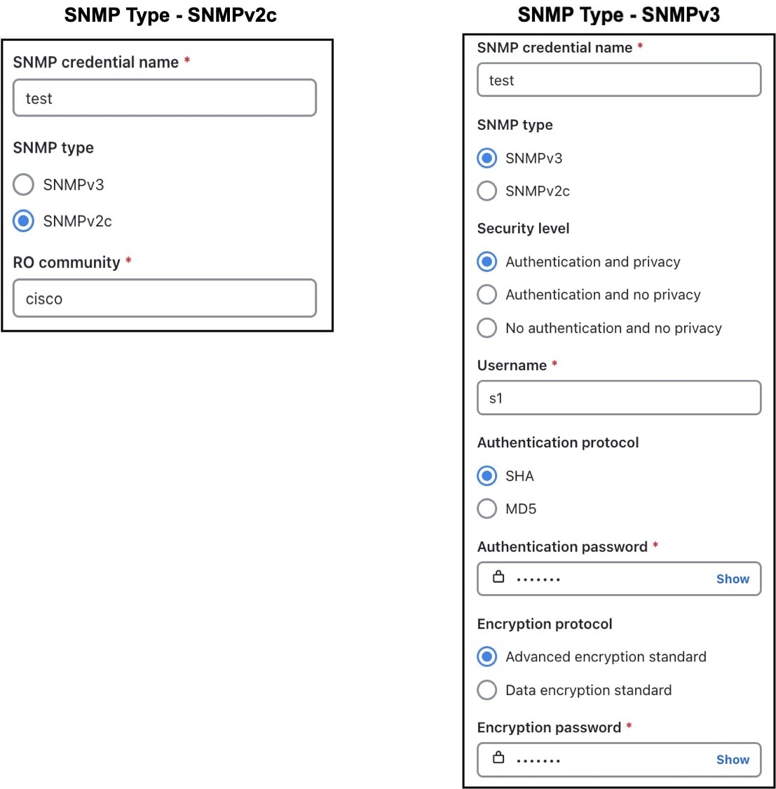
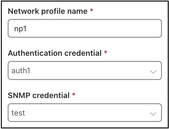
1. Configure device authgroups, SNMP groups, and network profile access. |
|
|
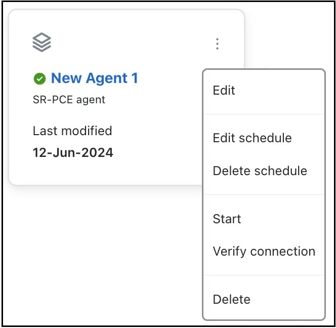
2. (Optional) Configure agents only if you need to collect SR-PCE or NetFlow information. |
See Configure agents. |
|
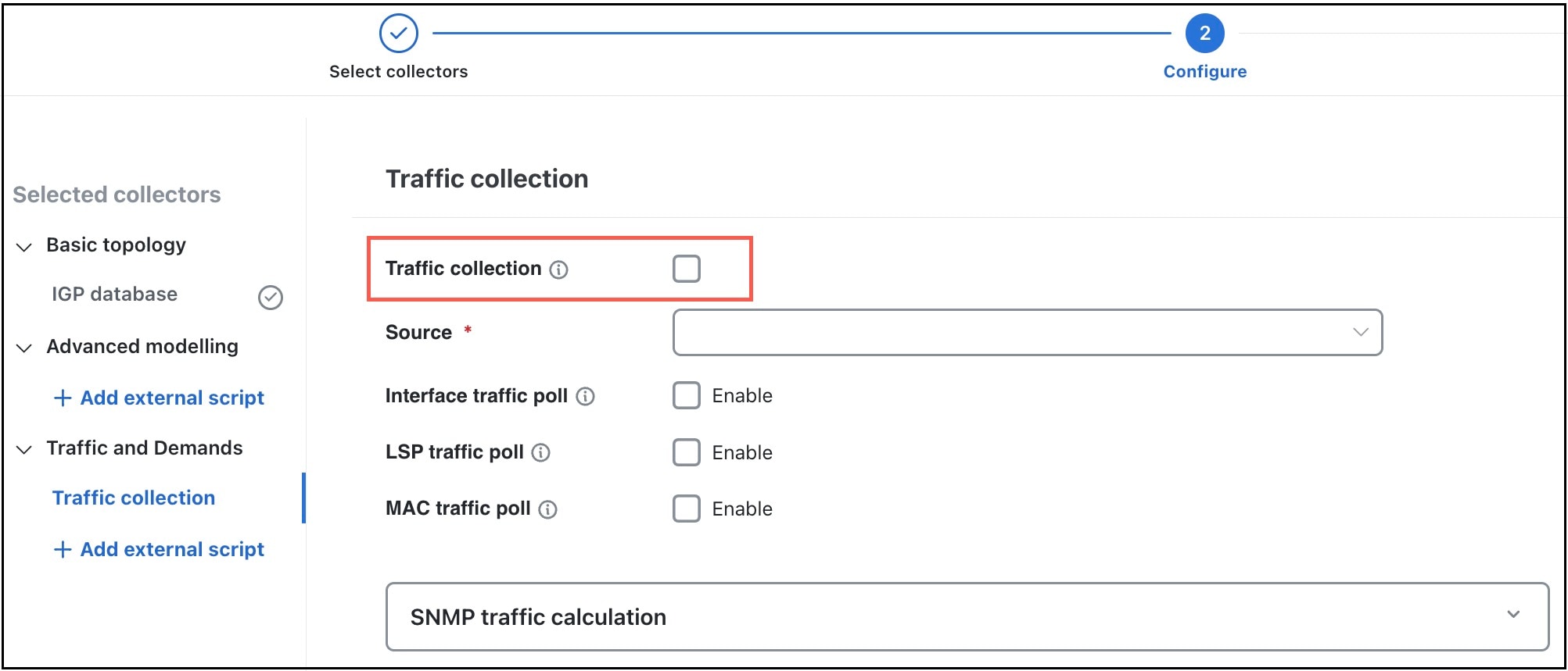
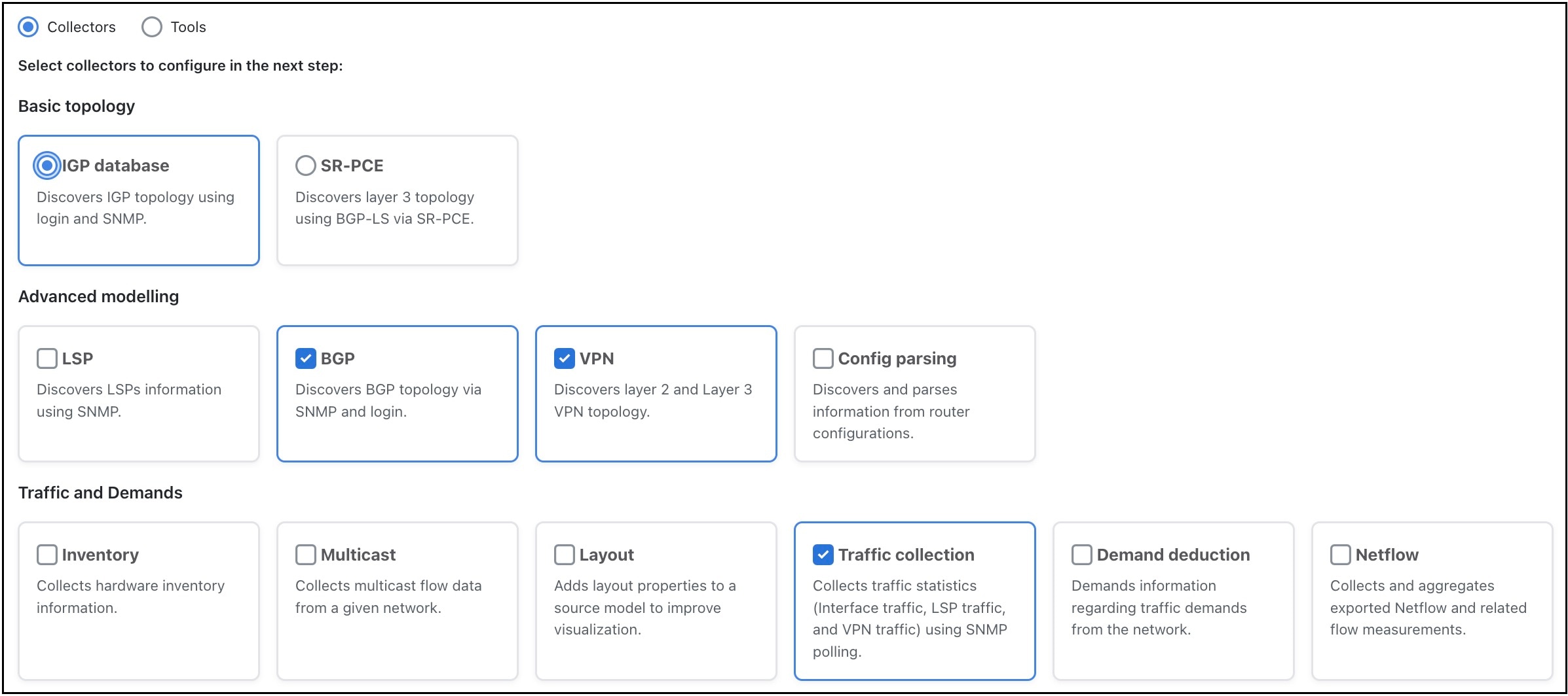
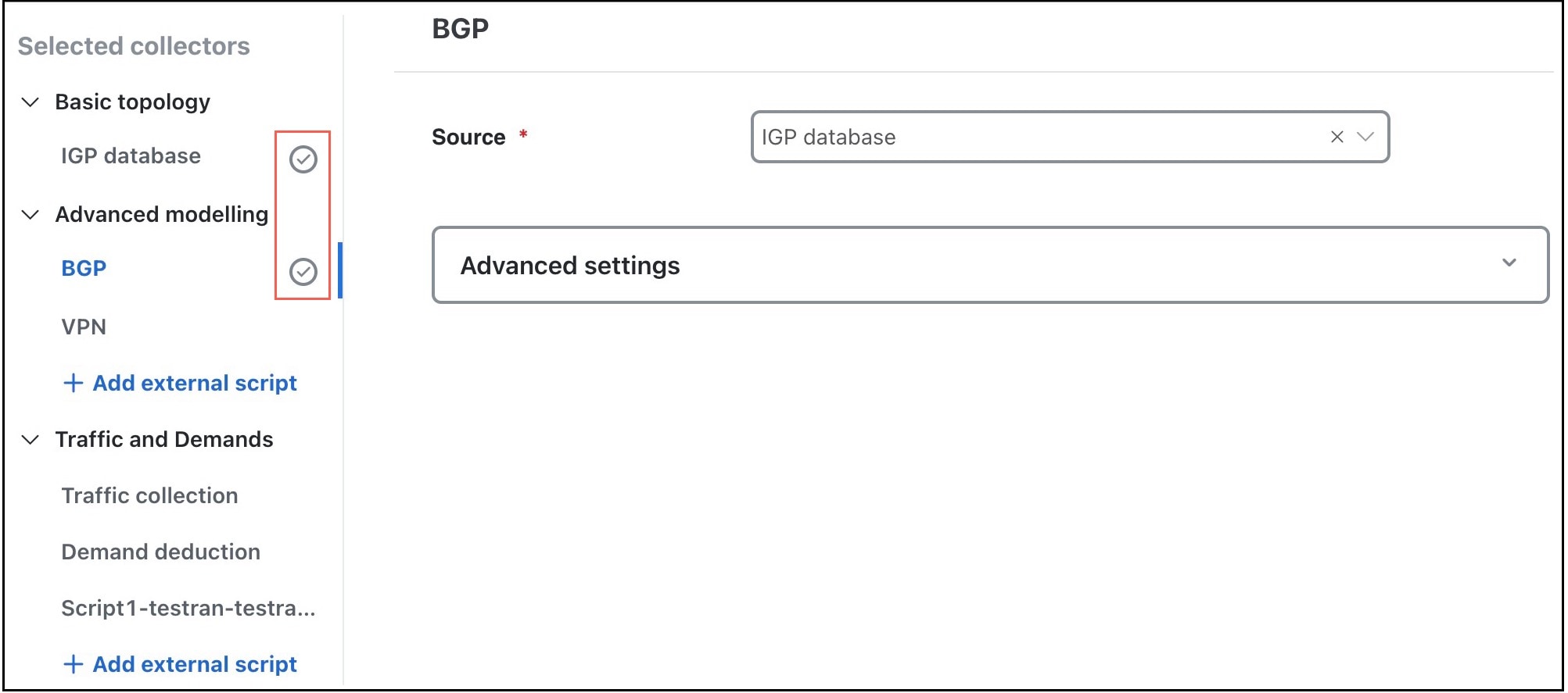
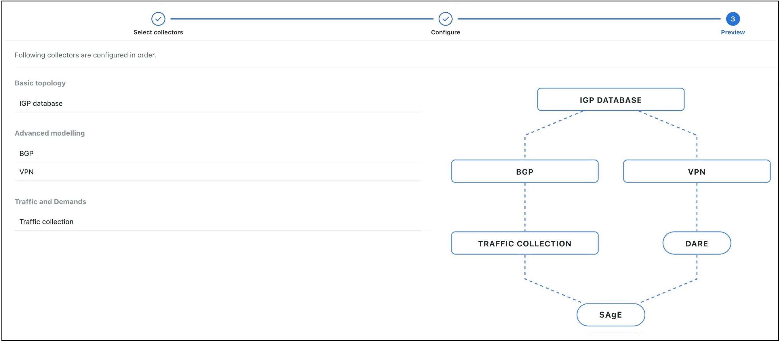
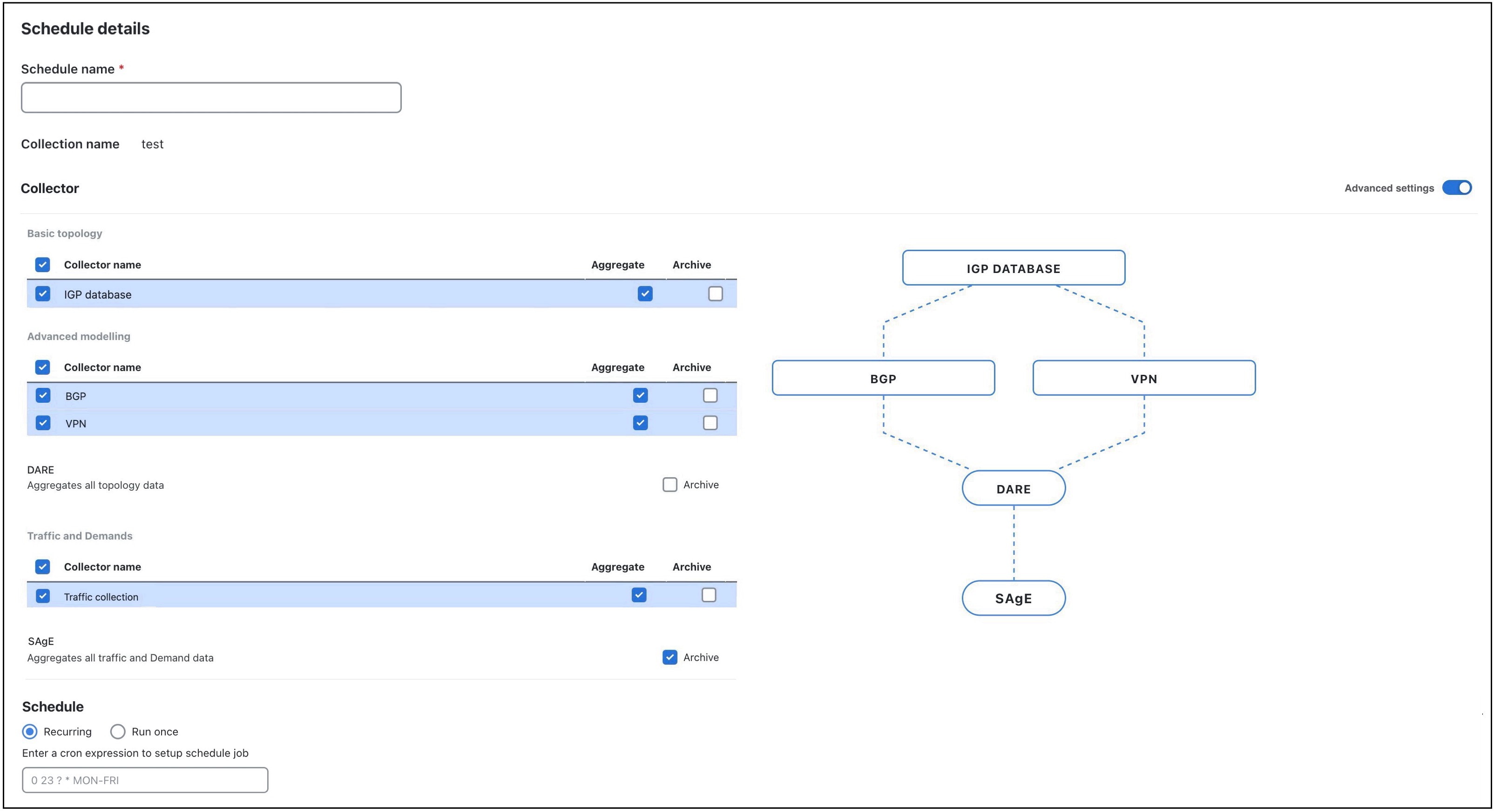
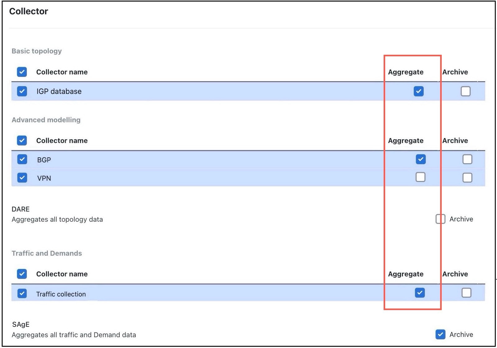
3. Configure the collections (basic and advanced configurations). |
|
|
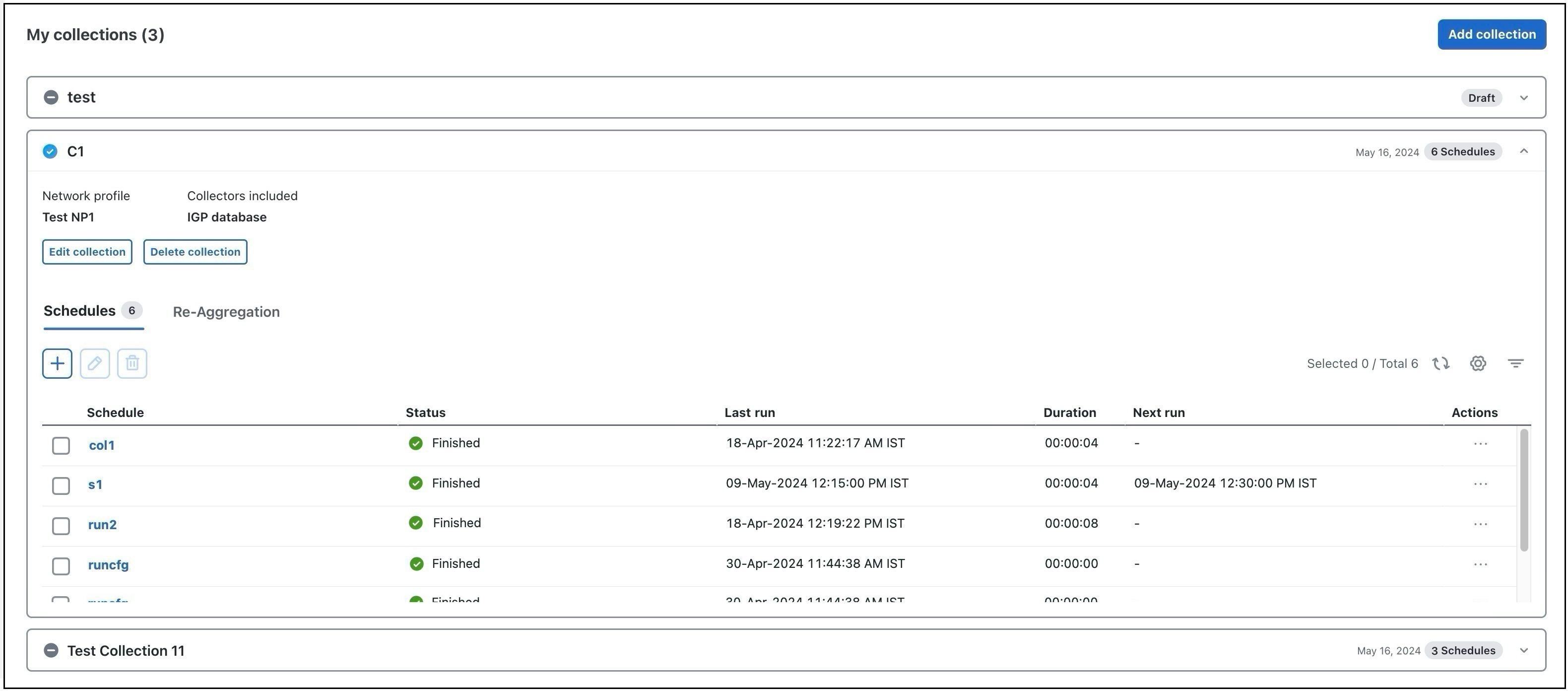
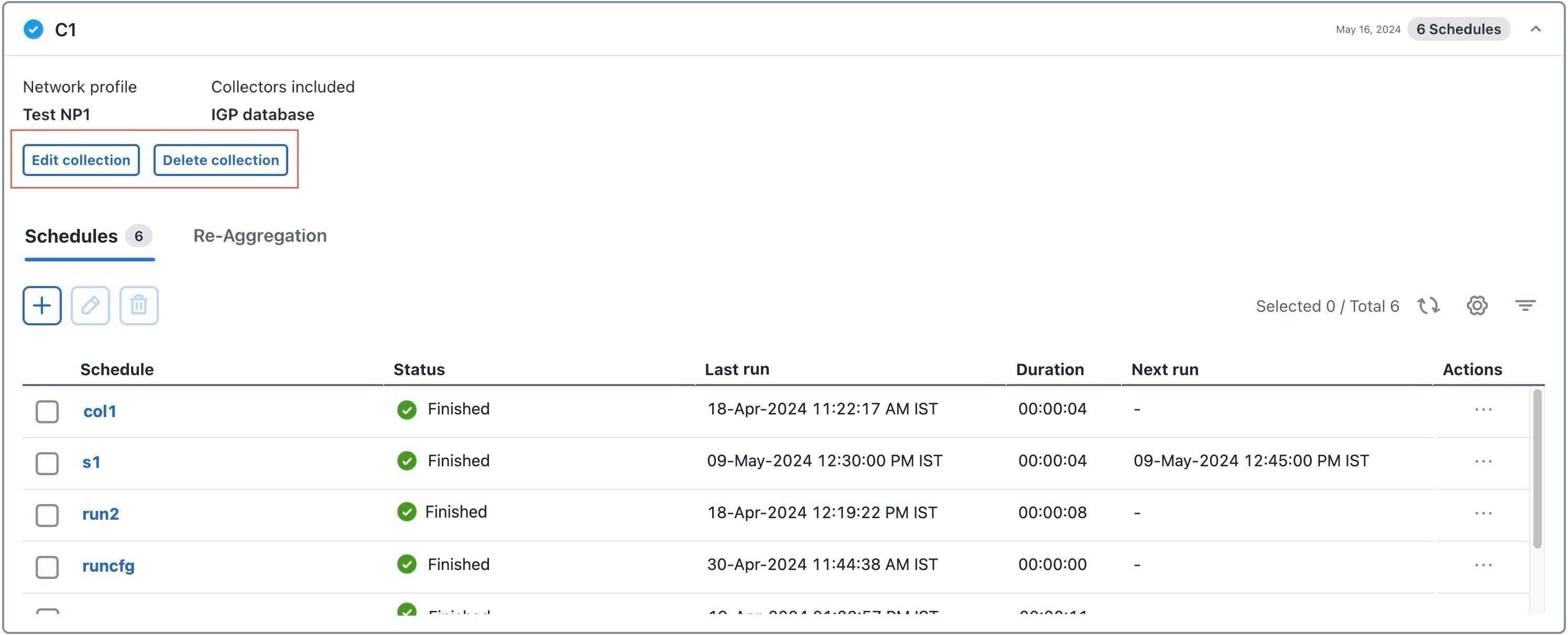
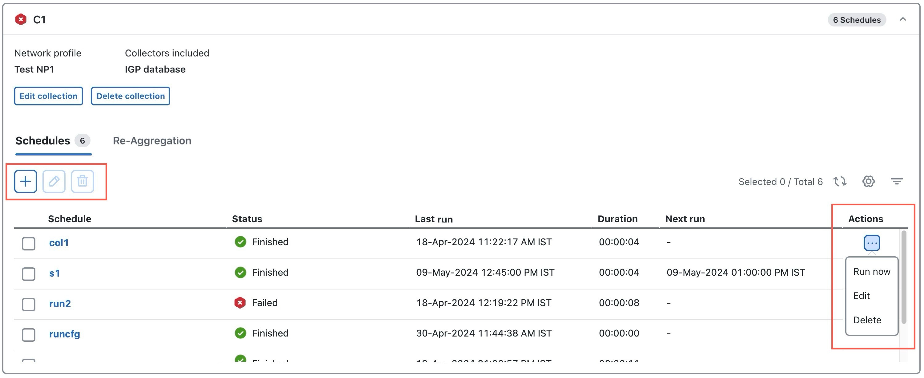
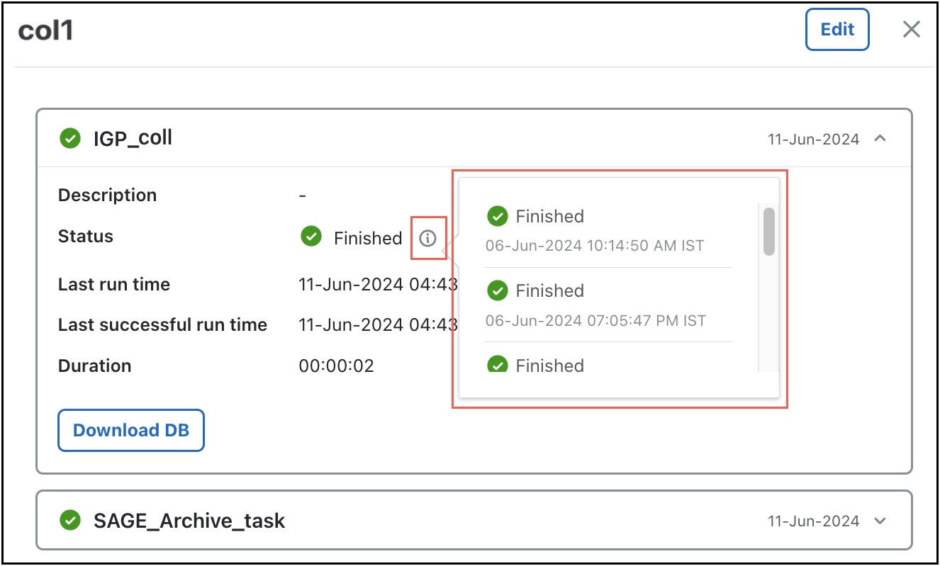
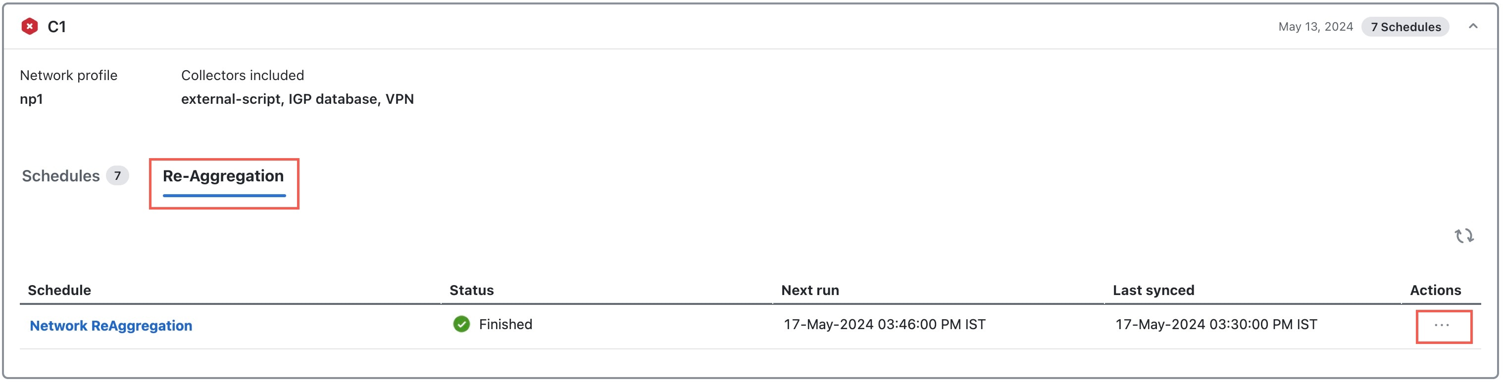
4. Schedule when to run the collections. |
See Schedule collections. |
|
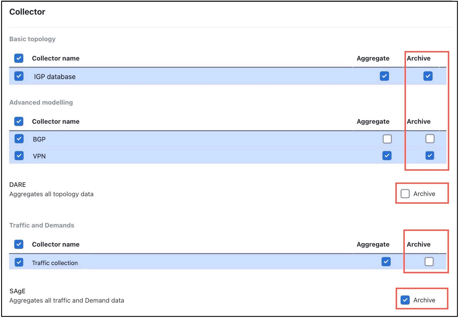
5. (Optional) Manage aggregation and archiving of network model as per your requirement. |
See |
|
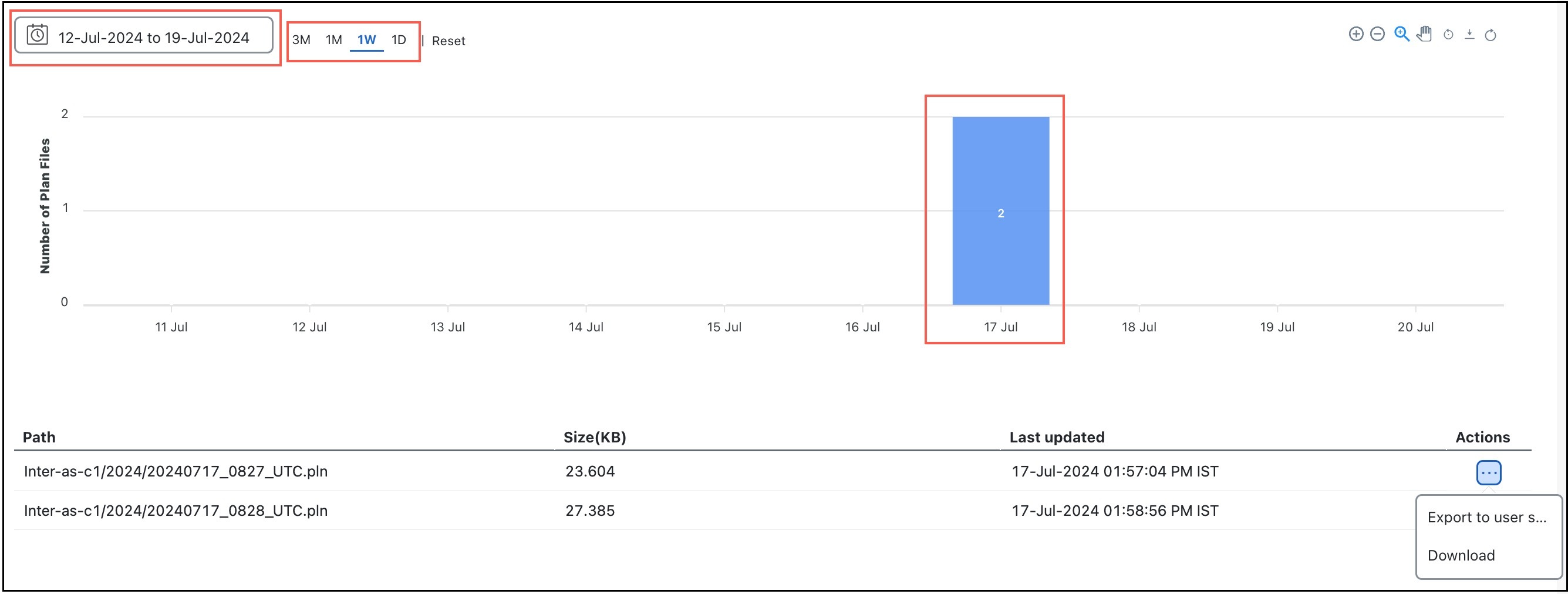
6. View or download the plan files in the Cisco Crosswork Planning Design application. |

 .
.
 .
.
 Feedback