Explains how external alarm pins enable connection of multiple alarm inputs to the switch, providing custom alarm triggers and severity notifications.
You can connect up to four alarm inputs from external devices in your environment, such as a door, a temperature gauge, or a fire alarm, to the alarm input port on the switch front panel. For each alarm input, you can configure an open or closed circuit to trigger an alarm. You can also configure the severity of the alarm.
The figure shows the alarm input pin details for setting up external alarms.
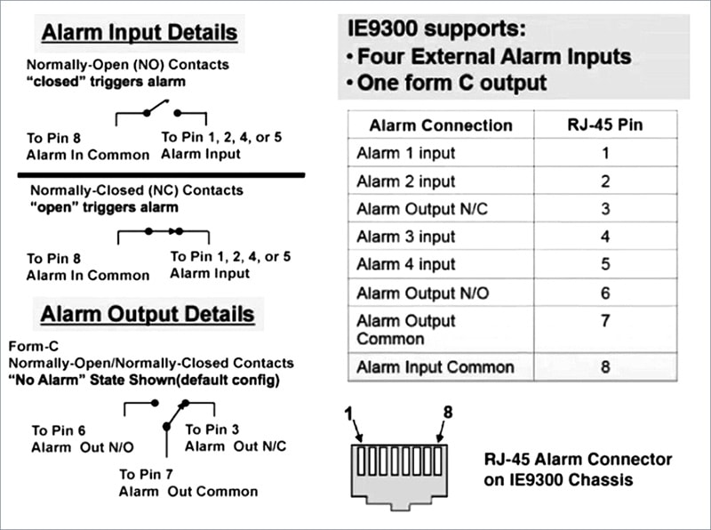
The alarm input circuit is designed to sense whether a dry contact is open or closed relative to the Alarm-In reference pin.
The Alarm Out is a relay with Normally Open and Normally Closed contacts.
The switch software is configured to detect faults. Detected faults energize the relay coil and change the state of output alarm relay contacts. Both internal faults and external input alarms can be relayed to the output alarm pins.
The input alarm trigger setting can be either open or closed. If the alarm trigger setting is not specified, the alarm is triggered when the circuit closes.
-
Open means that, under normal conditions, current flows through the contact (which indicates a normally closed contact). The alarm is generated when the current stops flowing.
-
Closed means that, under normal conditions, no current flows through the contact (which indicates a normally open contact). The alarm is generated when current begins to flow.
A triggered alarm generates a system message. A triggered alarm also turns on the LED display (the LED is normally off, meaning no alarm). You can set the severity of the input alarm to major, minor, or none. The severity is included in the alarm message and also sets the LED color when the alarm is triggered. The LED displays a solid red for a minor alarm and flashing red for a major alarm. If not set, the default alarm severity is minor. See Configure external alarms for details on how to configure external alarms.