Device Level Ring

Device Level Ring

Device Level Ring overview

Device Level Ring (DLR) is a Layer 2 protocol that enables redundancy in a ring topology, providing fast network fault detection and reconfiguration for industrial networks. DLR is an EtherNet/IP™ protocol that is defined by the Open DeviceNet® Vendors’ Association (ODVA).

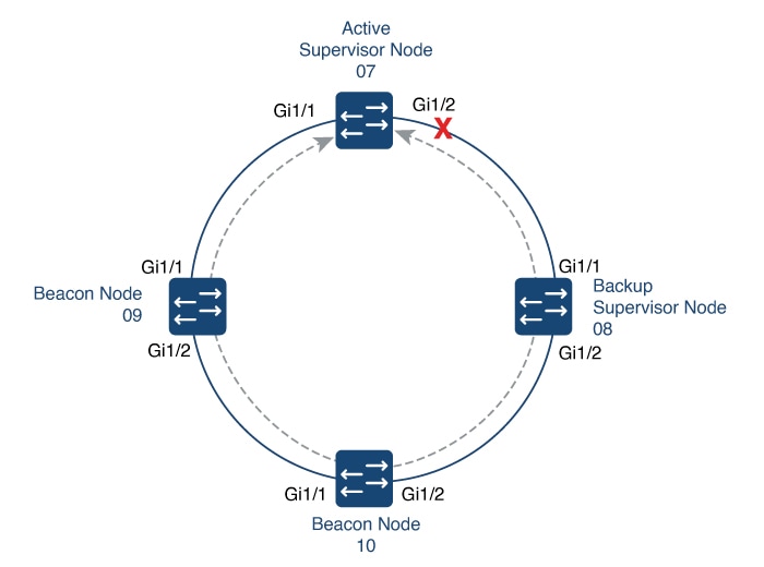
DLR network includes at least one node configured to be a ring supervisor, and any number of normal ring nodes. All DLR ring nodes are required to have at least two Ethernet ports and incorporate embedded switch technology. Non-DLR multiport devices—switches or end devices—may be present in the ring, subject to certain implementation constraints. (No MAC table filtering is one example.) Non-DLR devices also affect the worst-case ring recovery time.

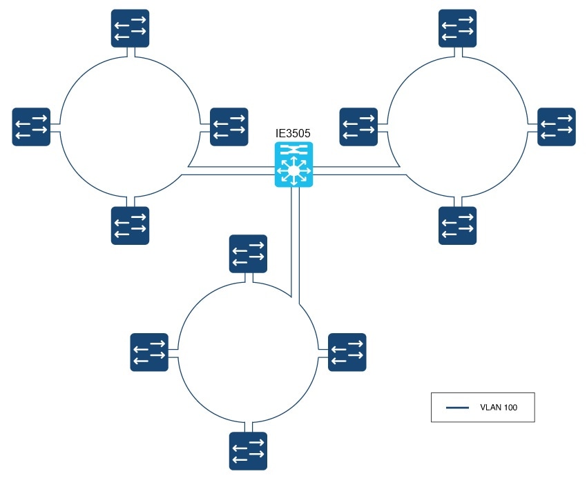
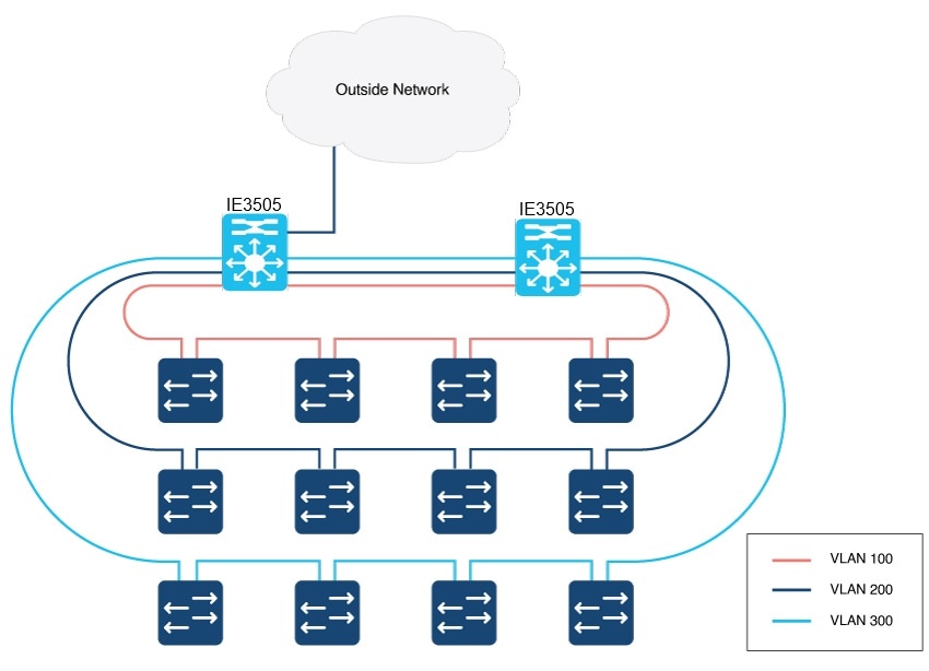
The DLR protocol supports a simple, single-ring topology. However, a network installation may use more than one DLR-based ring, so long as each ring is isolated so that DLR protocol messages from one ring are not present on another ring.

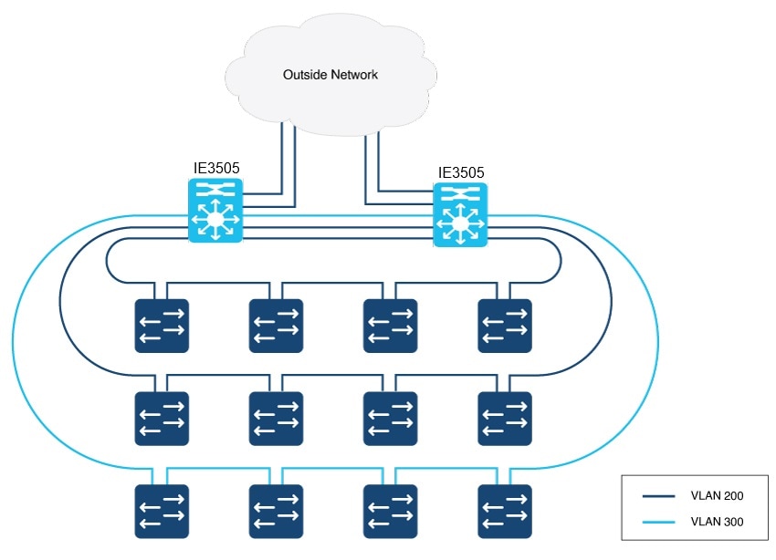
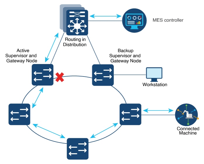
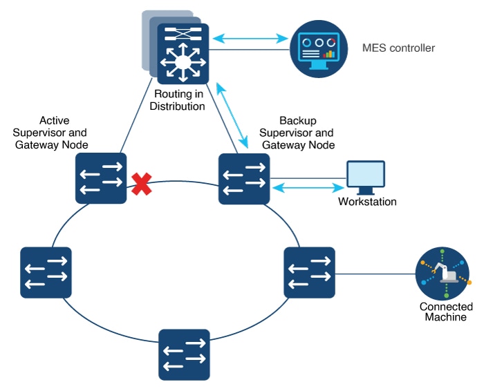
DLR supports redundant gateways for connecting with network infrastructure outside of the DLR network. The DLR redundant gateway feature provides mechanisms for automatically or manually selecting an active gateway. It also provides for automatic switchover to a backup gateway in the event of a connection failure.

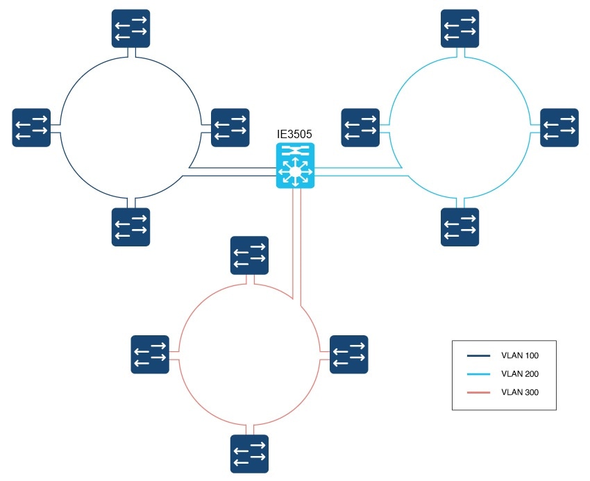
A DLR ring can operate on access or trunk interfaces. A DLR ring configured with access ports can connect switches or end nodes. A DLR ring with trunk interfaces serves as an infrastructure that connects DLR-capable switches and devices in multiple VLANs. All the interfaces on the ring should have the same VLAN membership.

Components of DLR

DLR Device Classes

DLR supports the given classes of devices:

  • Ring supervisor: On every DLR network, you must configure at least one device as the ring supervisor. The ring supervisor verifies the integrity of the ring, reconfigures it when a fault occurs, and collects diagnostic information. The ring supervisor also sends and processes Beacon frames at the default beacon interval of 400 microseconds.

    We recommend that you make at least one other device on the DLR network available as a back-up ring supervisor. Each supervisor is configured with a precedence value; the device with the highest precedence value becomes the active ring supervisor.

  • Beacon-based ring node: This class of device implements the DLR protocol, but lacks ring supervisor capability. The device must be able to process and act on the beacon frames that the ring supervisor sends.

  • Redundant Gateway: In a DLR network, redundant gateway devices enable multiple connections to the network outside of the DLR network. They provide an alternate path for communication in case a gateway device or its connection to the outside network fails.

    For information about redundant gateways, see the sections Redundant Gateways and Configure a Redundant Gateway.

  • VLAN trunking: VLAN trunking devices allow a DLR network to carry traffic through a trunk link. A trunk link connects switches that carry traffic from multiple VLANs, unlike an access link that can only carry a single VLAN.

    DLR VLAN trunking allows switches and star-connected devices in multiple VLANs to communicate through a DLR network. Traffic that passes from one switch to the next can either remain on the same VLAN or pass to a different VLAN through routing.

  • Multiple Rings support: Cisco IE3500 Rugged Series Switches and Cisco IE3500 Heavy-Duty Series Switches support up to three rings.

Default and Redundancy FPGA Profiles

Because the DLR feature requires use of the Cisco IE3505 Series Switch FPGA, the number of DLR rings supported on the Cisco IE3505 Series Switch depends on the FPGA profile. The default FPGA profile on the Cisco IE3505 Series Switch base system supports three DLR rings, while the redundancy profile supports two DLR rings, regardless of the presence of an expansion module. For information about FPGA profile, see Configure FPGA Profile

The Cisco IE3505 Series Switch expansion modules have product ID prefix IEM-3500. The switch allow you to configure all DLR rings either on the base module, on the expansion module, or as a mix of both, without restrictions.

The Cisco IE3505 Series Switch can support a maximum of three DLR rings with the default FPGA profile and two rings with the redundancy profile.

DLR Topology

The Cisco IE3505 Rugged Series Switches and Cisco IE3505 Heavy-Duty Series Switches can act as a DLR ring supervisor, backup supervisor, or regular DLR beacon node. This functionality helps other nodes that are connected in a DLR with Cisco IE3505 Rugged Series Switches and Cisco IE3505 Heavy-Duty Series Switches to recover from a ring fault within 3 milliseconds and resume communications.

The following illustration shows a DLR ring with Cisco IE3505 Rugged Series Switches and Cisco IE3505 Heavy-Duty Series Switches acting as the ring supervisor, backup supervisor, and beacon nodes. The solid blue line represents the ring over which Ethernet frames travel, and the dotted gray line represents the bidirectional beacon frames. The X in the illustration shows where the ring supervisor blocks an interface to prevent broadcast storms. If a failure occurs in the DLR ring, the supervisor will unblock the interface.

Figure 1. DLR Topology

We recommend that you connect the interface with the higher number on the active supervisor node to the backup supervisor node.

Multiple Rings

The Cisco IE3505 Rugged Series Switches and IE3505 Heavy-Duty Series Switches support up to three rings.

Multiple Rings, Single Switch, Single VLAN

The following restrictions apply to multiple rings that are connected to one switch on one VLAN:

  • Multiple rings cannot share the same ring ports.

  • Ring ports supports access ports and trunk ports.


    Note


    Ensure that all nodes in the same ring use the same access ports and trunk ports.


  • All ports participating in the ring must have the same VLAN mode. If an access ring is configured, then all ports must be in the same access VLAN. For a trunk ring, all ports must be in trunk mode.

When only one node is a member of multiple rings, as in the example below, a VLAN can have ports in more than one ring.

Figure 2. Multiple Rings, Single Switch, Single VLAN

Multiple Rings, Single Switch, Multiple VLANs

The following illustration shows multiple rings sharing a common supervisor with unique VLANs for each ring. When each DLR ring operates in a different VLAN, there is no issue and this is a supported deployment.

Figure 3. Multiple Rings, Single Switch, Multiple VLANs

Multiple Rings Connected to Multiple Switches

You can also use multiple rings with multiple Cisco IE3500 Series Switches, as shown in the illustration below. Depending on the configuration of the switches, VLAN restrictions can apply.

If the two switches are configured as redundant gateways for the same set of rings, there are no VLAN restrictions. The following example shows two rings on the same VLAN and one ring on a separate VLAN. However, because there are no VLAN restrictions, you can also configure all three rings on the same VLAN or all three on separate VLANs.

When there are two or more switches in same DLR, and they are not configured as redundant gateways, then each DLR ring must have a unique VLAN. VLANs and mutiple DLR rings need to be planned, especially when the VLAN or VLANs are present on more than one DLR ring. Configuring redundant gateways on the IE switches enables DLR deployments where a VLAN is present on multiple DLR rings. When the DLR gateway is not configured on the IE switch pair, then a VLAN cannot be shared across rings. Failure to adhere to this guidance will result in a Layer 2 loop. In example below, the two IE switches are configured for DLR gateway, thus a VLAN can be present across two or more DLR rings.

Figure 4. Multiple Rings, Multiple Switches, No VLAN Restrictions

If the two switches are not configured as redundant gateways, VLANs cannot be present on more than one ring, otherwise a Layer 2 loop becomes possible. The following illustration shows only one path out of the DLR ring, so DLR redundant gateways have not been configured.

Figure 5. Vlans Not Shared Across DLR Rings

Redundant Gateways

A DLR network with redundant gateways uses multiple switches to provide multiple connections from a ring to the outside network. Redundant gateways are not essential if you need only one connection to the outside network, but they provide extra network resiliency if an uplink connection fails.

Either a ring supervisor or a ring participant can be a redundant gateway; however, you must enable and configure DLR on both gateway switches.

Redundant gateways enable you to automatically or manually chose an active gateway as well as for automatic switchover to a backup gateway in case of a connection failure. Gateway switchover times range from 14 ms to 6.1 seconds, depending on the uplink network resiliency protocol. DLR redundancy gateway performance applies to traffic sourced from inside the DLR destined to the outside network:

  • Uplink connection failure detected by the active gateway at the physical layer is anywhere from 14 to 150 ms.

  • Failure of the Active Gateway Node can take between 19 and 150 ms.

System performance, which applies to most applications, describes traffic sourced from the outside network destined to the DLR. Higher layer uplink fault detection is up to 6.1 seconds.

DLR gateway convergence depends on the redundancy protocol running on the gateway interfaces. STP and REP have different convergence times. Traffic in and out of the DLR ring to the outside network should converge on failure to match the protocol used.

The following illustration shows traffic flow in and out of a DLR ring through the active DLR gateway.

Figure 6. DLR Active Gateway Traffic Flow

The following illustration shows traffic flow in and out of a DLR ring through the backup DLR gateway for devices directly connected to the backup gateway node. It is important to understand the physical path devices take to communicate with other applications outside the ring. The devices attached to the configured backup gateway take a different path than devices attached to the active gateway or other nodes in the DLR ring.

Figure 7. DLR Backup Gateway Traffic Flow

For more information about redundant gateways, see Guidelines for Using Device Level Ring (DLR) with Ethernet/IP™ on the odva.org website.

Cisco IE Switch Support for DLR

The Cisco IE3505 Rugged Series Switches and IE3505 Heavy-Duty Series Switches support DLR.

Switches that Support DLR

Table 1. The following Advanced base modules SKUs (PIDs) supports DLR.

Switch

PID

Cisco IE3505 Rugged Series Switch

IE-3505-8P3S

IE-3505-8T3S

Cisco IE3505 Heavy-Duty Series Switch

IE-3505H-16T

Table 2. The following Expansion modules PIDs include DLR support when installed on one of the above advanced base modules

Switch

Expansion modules PID

Cisco IE3500 Series Switch

IEM-3500-14T2S

IEM-3500-6T2S

IEM-3500-16P

IEM-3500-16T

IEM-3500-8P

IEM-3500-8S

IEM-3500-8T

Support for DLR is available on Network Essentials and Network Advantage licenses.

Supported DLR Features

IE-3505-8P3S, IE-3505-8T3S, and IE-3505H-16T switches support the following DLR features:

  • Three DLR rings for each switch and expansion model combination as shown in the following table.

    Table 3. Ring Support for Cisco IE3505 Series Switch and Expansion Models

    Switch

    FPGA Profile

    Number of Rings

    Cisco IE3505 Rugged Series without expansion module

    Default

    3

    Redundancy

    2

    Cisco IE3505 Rugged Series with expansion module

    Default

    3

    Redundancy

    2

    IE-3505H-16T

    Default

    3

    Redundancy

    2

  • Redundant gateway

  • Web User Interface (WebUI): DLR can be configured using the WebUI.

  • Common Industrial Protocol (CIP): DLR can be configured using CIP.

Differences Between Switch Models When Using DLR

Port mapping for IE3505 Heavy-Duty Series Switches differs from port mapping for IE3505-8P3S and IE3505-8T3S Rugged Series Switches.

For IE3505-8P3S and IE3505-8T3S Rugged Series Switches, DLR is supported on the base system (Gi1/1, Gi1/2), (Gi1/4, Gi1/5), (Gi1/6, Gi1/7), (Gi1/8, Gi1/9), and (Gi1/10, Gi1/11), and on the expansion module Gi2/1 through Gi2/8.

Table 4. Cisco IE3505 Rugged Series Switch Port Pairing

Module

Valid DLR Ring Port Pairs

Base module

  • [Gi1/1, Gi1/2]

  • [Gi1/4, Gi1/5]

  • [Gi1/6, Gi1/7]

  • [Gi1/8, Gi1/9]

  • [Gi1/10, Gi1/11]

Expansion module

  • [Gi2/1, Gi2/2]

  • [Gi2/3, Gi2/4]

  • [Gi2/5, Gi2/6]

  • [Gi2/7, Gi2/8]

For Cisco IE3505 Heavy-Duty Series Switches, you must pair DLR ring ports with adjacent ports. The following table shows valid DLR ring port pairs:

Table 5. Cisco IE3505 Heavy-Duty Switch Port Pairing

Ports

Valid DLR Ring Port Pairs

Gi1/1 through Gi1/8

  • [Gi1/1, Gi1/2]

  • [Gi1/3, Gi1/4]

  • [Gi1/5, Gi1/6]

  • [Gi1/7, Gi1/8]

Gi1/9 through Gi1/16

  • [Gi1/9, Gi1/10]

  • [Gi1/11, Gi1/12]

  • [Gi1/13, Gi1/14]

  • [Gi1/15, Gi1/16]

DLR Feature Interactions

The following list contains features that cannot be configured on interfaces that are also configured as DLR ring ports..

  • STP, RSTP, and MSTP

  • 802.1x and Guest VLAN

  • PVLAN and PVLAN Edge

  • VLAN Routing and Bridging and MV

DLR does not interfere with the functionality of the following features. However, take care during configuration: The MAC or IP addresses of the DLR devices must be included in the allowable list.

  • Port Security

  • Unicast MAC filter

  • DAI

  • DHCP Snooping

For the following features, the ports forward IGMP packets between the two DLR ports but do not process them. Devices other than gateways and active redundant gateway devices are unaffected.

  • Multicast

  • IGMP Snooping

Guidelines and Limitations

The following restrictions apply to DLR configuration and operation:

  • You can configure up to three DLR rings at the same time on each the Cisco IE3505 Rugged Series Switches and IE3505 Heavy-Duty Series Switches. See use cases in Multiple Rings for guidance.

  • When configuring DLR Gateways, for each node, you can configure two ports as an uplink. An uplink can belong to more than one ring.

  • We recommend that you configure no more than one backup gateway for each ring.

  • MAC learning for each ring is limited to 1024 unicast MAC addresses and 128 multicast MAC addresses for each he Cisco IE3505 Rugged Series Switches and IE3505 Heavy-Duty Series Switches.

  • Multicast MAC learning through IGMP snooping is limited to 128 addresses.

  • Duplicated packets may be observed during ring convergence.

  • DLR is supported on 1 Gbps links and 100 Mbps interfaces with full duplex capability. DLR does not support half duplex links.

  • On a given physical ring, all the nodes must be configured with same ring- ID If there is any mismatch in ring IDs between nodes (due to misconfiguration), the ring will still converge and may lead to unexpected behavior.

The following restrictions apply to configuring multiple DLR rings:

  • Multiple rings cannot share the same ring ports.

  • The switch cannot be configured as announce-based node.

  • The default beacon interval is 400 usec. This is the recommended interval for 1 Gbps and 100 Mbps ring interface speeds. The default beacon timeout is 1960 usec. This is the recommended value.

  • DLR ring ports are supported on IEM-3500 expansion modules. Check the Product ID (PID) of any expansion modules attached to the IE3505 before attempting to configure DLR rings on expansion module ports.


Note


For information, including limitations, on DLR interactions with other features and protocols, see the section DLR Feature Interactions in this guide.


Configuring DLR

The following sections provide information for configuring DLR on IE3505 Rugged Series Switches and IE3505 Heavy-Duty Series Switches. The supervisor node with the highest precedence value is elected to operate as DLR supervisor. You can use this feature to plan which node will be active and which will be backup supervisor.

Configure a Ring Supervisor

Complete the following procedure to configure the switch as a ring supervisor.

Before you begin

Refer to the parameters for configuring a DLR ring supervisor, which are shown in the following table.

Parameter

Range

Default

Beacon interval

200 to100,000 microseconds

400 microseconds

Beacon timeout

200 to 500,000 microseconds

1960 microseconds

Precedence

0 to 255

0

control-vlan-id

0 to 4095

0

Procedure

  Command or Action Purpose

Step 1

dlr ring ring_number

Example:

switch(config)#dlr ring 1

Provide the unique DLR value identifying a ring.

Step 2

mode device_role

Example:

switch(config)#mode supervisor

Configure the DLR device as a ring supervisor.

Step 3

beacon-interval microseconds

Example:

switch(config)#beacon-interval 500

Set the beacon interval.

Note


You can set the beacon interval only for devices in supervisor mode.

Step 4

beacon-timeout microseconds

Example:

switch(config)# beacon-timeout 2500

Set the beacon timeout.

Note


You can set the beacon timeout only for devices in supervisor mode.

Step 5

precedence rank

Example:

switch(config)#precedence 100

Sets the precedence of the ring supervisor.

Step 6

interface interface_name

Example:

switch(config)#interface gigabitEthernet 1/1

Enter interface configuation submode for interface GigabitEthernet 1/1.

Step 7

switchport mode access

Example:

switch(config-if)#switchport mode access
switch(config-if)#switchport access vlan 33

Configure the interface to be a member of a single VLAN.

Step 8

dlr ring 1

Example:

switch(config-if)#dlr ring 1

Configure the interface to be a member of a DLR ring.

Step 9

interface

Example:

switch(config)#interface gigabitEthernet 1/2

Set the interface for the second DLR ring port. The second DLR ring port must be a valid port pair of the first DLR ring port. See the section Cisco IE Switch Support for DLR in this guide for valid port pair combinations.

Step 10

switchport mode access

Example:

switch(config-if)#switchport mode access
switch(config-if)#switchport access vlan 33

Configure the interface to be a member of a single VLAN. The VLAN must be the same as the one used by the other interface to be a port on same DLR ring.

Step 11

dlr ring 1

Example:

switch(config-if)#dlr ring 1

Add interface for the DLR ring port.

What to do next

Verify that the ring supervisor is configured by entering the show command. The following example is output of the show command when the switch is configured as a ring supervisor:

Switch#sh dlr ring 1
DLR ring 1

mode: Active Supervisor
Network Topology: 				Ring Network Status: Normal
IOS state: NORMAL_ACTIVE 			Hardware State: NORMAL_ACTIVE
Transition bit = 0
Mac-Addr: 6C:13:D5:AC:3A:C3 IP-Addr: 0.0.0.0
Port1: GigabitEthernet1/1, vlan 33, 		UP Port2: GigabitEthernet1/2, vlan 33, UP
LastBcnRcvPort: Port 1: Yes 			Port 2: Yes

Active Supervisor Parameters:
Beacon Interval (usec): 500 			Beacon Timeout (usec): 2500
DLR VLAN ID: 0 					Precedence: 100
Mac-Addr: 6C:13:D5:AC:3A:C3 			IP-Addr: 0.0.0.0

Locally Configured Supervisor Parameters:
Beacon Interval (usec): 500 			Beacon Timeout (usec): 2500
DLR VLAN ID: 0 					Precedence: 100
Port1: GigabitEthernet1/1 			Port2: GigabitEthernet1/2

Configure a Beacon-Based Ring Node

Procedure


Complete the commands as shown in the following example to configure the switch as a beacon-based ring node.

Example:

…
dlr ring 2
   mode beacon-node 
!
…
interface GigabitEthernet1/1
   switchport mode trunk
   dlr ring 2
!
interface GigabitEthernet1/2
   switchport mode trunk
   dlr ring 2
!
…

What to do next

Verify that the beacon-based ring node is configured by entering the show command. The following example is output of the show command when the switch is configured as a beacon-based ring node:

Switch#show dlr ring 2
DLR ring 2
mode: Beacon Node
Network Topology: Ring 				Network Status: Normal
IOS state: NORMAL 				Hardware State: NORMAL
Transition bit = 0
Mac-Addr: 6C:13:D5:AC:3C:03 IP-Addr: 0.0.0.0
Port1: GigabitEthernet1/1, vlan Trunk, UP 	Port2: GigabitEthernet1/2, vlan Trunk, UP
LastBcnRcvPort: Port 1: Yes 			Port 2: Yes

Active Supervisor Parameters:
Beacon Interval (usec): 400 			Beacon Timeout (usec): 1960
DLR VLAN ID: 0 Precedence: 0
Mac-Addr: 6C:13:D5:AC:3A:C3 			IP-Addr: 0.0.0.0

Locally Configured Beacon Node Parameters:
Port1: GigabitEthernet1/1 			Port2: GigabitEthernet1/2

Configure a Redundant Gateway

You must configure DLR on both gateway switches.

Before you begin

Refer to the parameters for configuring a switch as a DLR redundant gateway node. The parameters are shown in the following table:

Parameter

Range

Default

Gateway enable

Enable-Disable

Disable

Precedence

0 to 255

0

Advertise interval

200 to 100,000 microseconds

2000 microseconds

Advertise timeout

500 to 500,000 microseconds

5000 microseconds

Learning-update

Supported

Enabled

Procedure


Complete the commands as shown in the following example to configure the switch as a redundant gateway node.

Example:

Switch A Configuration

Switch B Configuration

…
dlr ring 1
 mode supervisor
dlr ring 1
 gateway enable
  gateway-precedence 100
  advertise-interval 3000
  advertise-timeout 10000

interface GigabitEthernet1/9
 switchport mode trunk
 dlr ring 1 uplink
!…
…
dlr ring 1
 mode supervisor
dlr ring 1
 gateway enable
  gateway-precedence 255
  advertise-interval 3000
  advertise-timeout 10000

interface GigabitEthernet1/9
 switch mode trunk
 dlr ring 1 uplink
!…

What to do next

Verify that the redundant gateways are configured by entering the show command.

The following example is output of the show command when a switch is configured as the redundant gateway nodes:

Switch-a#sh dlr ring 1
DLR ring 1

mode: Active Supervisor
Network Topology: Ring 			Network Status: Normal
IOS state: NORMAL_ACTIVE 		Hardware State: NORMAL_ACTIVE
Transition bit = 0
Mac-Addr: 6C:13:D5:AC:3C:03 IP-Addr: 0.0.0.0
Port1: GigabitEthernet1/1, vlan Trunk, UP Port2: GigabitEthernet1/2, vlan Trunk, UP
LastBcnRcvPort: Port 1: Yes 		Port 2: Yes

Active Supervisor Parameters:
Beacon Interval (usec): 400 		Beacon Timeout (usec): 1960
DLR VLAN ID: 0 				Precedence: 0
Mac-Addr: 6C:13:D5:AC:3C:03 IP-Addr: 0.0.0.0

Locally Configured Supervisor Parameters:
Beacon Interval (usec): 400 		Beacon Timeout (usec): 1960
DLR VLAN ID: 0 				Precedence: 0
Port1: GigabitEthernet1/1 		Port2: GigabitEthernet1/2
…
…
…
Redundant Gateway Information:
Redundant Gateway Status: Active Gateway
Hardware State: ACTIVE NORMAL
Mac-Addr: 6C:13:D5:AC:3C:03 IP_addr:0.0.0.0
Uplink Port(s): GigabitEthernet1/9

Active Gateway Parameters:
Advertise Interval (usec): 3000 	Advertise Timeout (usec): 10000
Precedence: 100 			Learning Update Enable: yes
Mac-Addr: 6C:13:D5:AC:3C:03 IP-Addr:0.0.0.0

Fault Statistics:
Gateway Faults since power up: 0

Locally Configured Gateway Parameters:
Advertise Interval (usec): 3000 	Advertise Timeout (usec): 10000
Precedence: 100 			Learning Update Enable: yes
Uplink Port(s): GigabitEthernet1/9
switch-a#

The following example is output of the show command when a switch is configured as the backup gateway:

Switch-b#sh dlr ring 1
-----------------------------------------
DLR ring 1

mode: Backup Supervisor
Network Topology: Ring 			Network Status: Normal
IOS state: NORMAL_BACKUP 		Hardware State: NORMAL_BACKUP
Transition bit = 0
Mac-Addr: 6C:13:D5:AC:3A:C3 IP-Addr: 0.0.0.0
Port1: GigabitEthernet1/1, vlan Trunk, UP Port2: GigabitEthernet1/2, vlan Trunk, UP
LastBcnRcvPort: Port 1: 		Yes Port 2: Yes

Active Supervisor Parameters:
Beacon Interval (usec): 400 		Beacon Timeout (usec): 1960
DLR VLAN ID: 0 				Precedence: 0
Mac-Addr: 6C:13:D5:AC:3C:03 IP-Addr: 0.0.0.0

Locally Configured Supervisor Parameters:
Beacon Interval (usec): 400 		Beacon Timeout (usec): 1960
DLR VLAN ID: 0 				Precedence: 0
Port1: GigabitEthernet1/1 		Port2: GigabitEthernet1/2
…
…
…
Backup Supervisor Precedence: 0

Redundant Gateway Information:
Redundant Gateway Status: Backup Gateway
Hardware State: BACKUP NORMAL
Mac-Addr: 6C:13:D5:AC:3A:C3 IP_addr:0.0.0.0
Uplink Port(s): GigabitEthernet1/9

Active Gateway Parameters:
Advertise Interval (usec): 3000 	Advertise Timeout (usec): 10000
Precedence: 100 			Learning Update Enable: yes
Mac-Addr: 6C:13:D5:AC:3C:03 IP-Addr:0.0.0.0

Fault Statistics:
Gateway Faults since power up: 0

Locally Configured Gateway Parameters:
Advertise Interval (usec): 3000 	Advertise Timeout (usec): 10000
Precedence: 0 				Learning Update Enable: yes
Uplink Port(s): GigabitEthernet1/9

Configure VLAN Trunking


Note


When a node has two or more DLR rings configured, a VLAN can only be present on one ring. When configuring DLR ring ports in trunk mode, you must edit the trunk-allowed VLAN list to ensure unique VLAN membership across DLR rings.


Procedure


Complete the commands as shown in the following example to configure VLAN trunking for DLR.

Example:

switch(config)#dlr ring 1
switch(config-dlr)#mode supervisor
switch(config-dlr-supervisor)#end

switch(config)#int gi1/1
switch(config-if)#switchport mode trunk
switch(config-if)#switchport trunk allowed vlan 10,20
switch(config-if)#dlr ring 1

switch(config-if)#
switch(config-if)#int gi1/2
switch(config-if)#switchport mode trunk
switch(config-if)#switchport trunk allowed vlan 10,20
switch(config-if)#dlr ring 1

What to do next

Verify that VLAN trunking is configured by entering the show command. The following example is the output of the show command when VLAN trunking is configured:

switch#sh dlr ring
-----------------------------------------
DLR ring 1

mode: Active Supervisor
Network Topology: Ring 				Network Status: Normal
IOS state: NORMAL_ACTIVE 			Hardware State: NORMAL_ACTIVE
Transition bit = 0
Mac-Addr: 6C:13:D5:AC:3A:C3 IP-Addr: 0.0.0.0
Port1: GigabitEthernet1/1, vlan Trunk, UP 	Port2: GigabitEthernet1/2, vlan Trunk, UP
LastBcnRcvPort: Port 1: Yes 			Port 2: Yes

Active Supervisor Parameters:
Beacon Interval (usec): 400 			Beacon Timeout (usec): 1960
DLR VLAN ID: 0 					Precedence: 0
Mac-Addr: 6C:13:D5:AC:3A:C3 IP-Addr: 0.0.0.0

Locally Configured Supervisor Parameters:
Beacon Interval (usec): 400 			Beacon Timeout (usec): 1960
DLR VLAN ID: 0 					Precedence: 0
Port1: GigabitEthernet1/1 			Port2: GigabitEthernet1/2

Ring Protocol Participants Count: 3
No    Mac-Addr IP-Addr
1     6C:13:D5:AC:3A:C3 0.0.0.0
2     6C:13:D5:AC:3C:03 0.0.0.0
3     6C:13:D5:AC:37:03 0.0.0.0

Fault Statistics:CIP

Ring Faults since power up: 0
Ring Fault Location 	Mac-Addr IP-Addr
Last Active Node on Port 1 00:00:00:00:00:000.0.0.0
Last Active Node on Port 2 00:00:00:00:00:000.0.0.0

Redundant Gateway Information:
Redundant Gateway Status: Gateway not enabled
-----------------------------------------
DLR ring 2 not configured

Enabling CIP

You can enable Common Industrial Protocol (CIP) on a device by applying the cip enable command on one of the Layer-3 interfaces—a physical L3 interface or an SVI-interface.


Note


Be aware of the following when enabling CIP:

  • You must habve DLR rings configured on the switch before enabling CIP.

  • You must enter the command in interface configuration mode.

  • You enable CIP at the device level.

  • You enable CIP only through one of the Layer-3 interfaces; if you try to enable CIP on another interface, an error occurs.


Enable CIP on the Layer 3 Interface

Complete the steps in this section to enable CIP on the Layer 3 interface.

Procedure

  Command or Action Purpose

Step 1

conf t

Enter configuration mode.

Step 2

interface interface_name

Example:

switch(config)#interface gigabitEthernet 1/10

Specify the interface.

Step 3

no switchport

Prevent the interface from forwarding Ethernet frames based on MAC addresses. The interface is not operational until a valid IP address is assigned.

Step 4

ip address IP_address subnet_address

Example:

switch(config-if)#ip address 192.168.1.10 255.255.255.0 

Set the IP address and subnet.

Step 5

cip enable

Enable CIP on the interface.

Step 6

end

Leave configuration mode.

What to do next

Verify that CIP is configured by entering the show command. The following example is output of the show command when CIP is configured:

DLR_node#show cip status
State : Enabled
Interface : Gi1/10
DLR_node#

Enable CIP on the SVI Interface

Complete the steps in this section to enable CIP on the SVI interface.

Before you begin

If the SVI is not vlan1, assign switchport access vlan vlan-id to the DLR ring.

Procedure

  Command or Action Purpose

Step 1

conf t

Enter configuration mode.

Step 2

vlan vlan_id

Example:

switch(config)#vlan 1

Specify the VLAN.

Step 3

int vlan vlan_id

Example:

switch(config-vlan)#int vlan 1

Enter interface configuration mode.

Step 4

ip address IP_address subnet_address

Example:

switch(config-if)#ip address 192.168.1.10 255.255.255.0

Specify an ID address and subnet.

Step 5

cip enable

Example:

switch(config-if)# cip enable

Enable CIP on the interface.

Step 6

end

Example:

switch(config-if)# end

Leave configuration mode.

What to do next

Verify that CIP is configured by entering the show command. The following example is output of the show command when CIP is configured:

DLR_node#show cip status
State : Enabled
Interface : Vlan 1
DLR_node#