Information About PRP
From Release 17.17.1, the Cisco IE3505 Rugged Series Switches and IE3505 Heavy-Duty Series Switches supports Parallel Redundancy Protocol (PRP).
Parallel Redundancy Protocol overview
PRP is defined in the International Standard IEC 62439-3. PRP is designed to provide hitless redundancy (zero recovery time after failures) in Ethernet networks.
To recover from network failures, redundancy can be provided by network elements connected in mesh or ring topologies using protocols like RSTP, REP, or MRP, where a network failure causes some reconfiguration in the network to allow traffic to flow again (typically by opening a blocked port). These schemes for redundancy can take between a few milliseconds to a few seconds for the network to recover and traffic to flow again.
PRP uses a different scheme, where the end nodes implement redundancy (instead of network elements) by connecting two network interfaces to two independent, disjointed, parallel networks (LAN-A and LAN-B). Each of these Dually Attached Nodes (DANs) then have redundant paths to all other DANs in the network.
The DAN sends two packets simultaneously through its two network interfaces to the destination node. A redundancy control trailer (RCT), which includes a sequence number, is added to each frame to help the destination node distinguish between duplicate packets. When the destination DAN receives the first packet successfully, it removes the RCT and consumes the packet. If the second packet arrives successfully, it is discarded. If a failure occurs in one of the paths, traffic continues to flow over the other path uninterrupted, and zero recovery time is required.
Non-redundant endpoints in the network that attach only to either LAN-A or LAN-B are known as Singly Attached Nodes (SANs).
A Redundancy Box (RedBox) is used when an end node that does not have two network ports and does not implement PRP needs to implement redundancy. Such an end node can connect to a RedBox, which provides connectivity to the two different networks on behalf of the device. Because a node behind a RedBox appears for other nodes like a DAN, it is called a Virtual DAN (VDAN). The RedBox itself is a DAN and acts as a proxy on behalf of its VDANs.
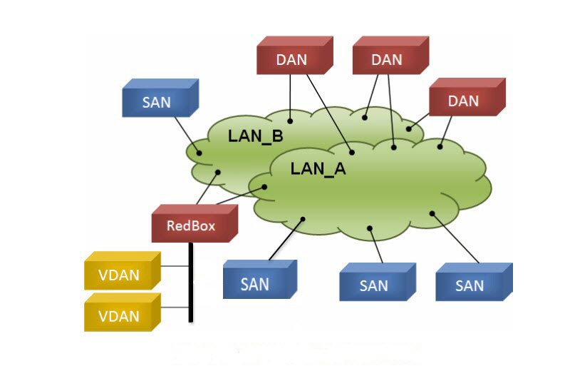
To manage redundancy and check the presence of other DANs, a DAN periodically sends Supervision frames and can evaluate the Supervision frames sent by other DANs.
Switches that Support PRP
|
Switch |
PID |
|---|---|
|
Cisco IE3505 Rugged Series Switch |
IE-3505-8P3S |
|
IE-3505-8T3S |
|
|
Cisco IE3505 Heavy-Duty Series Switch |
IE-3505H-16T |
|
Switch |
Expansion modules PID |
|---|---|
|
Cisco IE3505 Rugged Series Switch |
IEM-3500-14T2S |
|
IEM-3500-6T2S |
|
|
IEM-3500-16P |
|
|
IEM-3500-16T |
|
|
IEM-3500-8P |
|
|
IEM-3500-8S |
|
|
IEM-3500-8T |
Support for PRP is available on Network Essentials and Network Advantage licenses.
Supported PRP Features
IE-3505-8P3S, IE-3505-8T3S, and IE-3505H-16T switches support the following PRP features.
PRP supports maximum of two channel instance as shown in the following table:
|
Switch |
FPGA Profile |
Number of PRP Instance |
|---|---|---|
|
Cisco IE3505 Rugged Series without expansion module |
Default |
1 |
|
Redundancy |
2 |
|
|
Cisco IE3505 Rugged Series with expansion module |
Default |
1 |
|
Redundancy |
2 |
|
|
IE-3505H-16T |
Default |
1 |
|
Redundancy |
2 |
Role of the Switch
The switches implement RedBox functionality using Gigabit Ethernet port connections to each of the two LANs.
PRP Channels
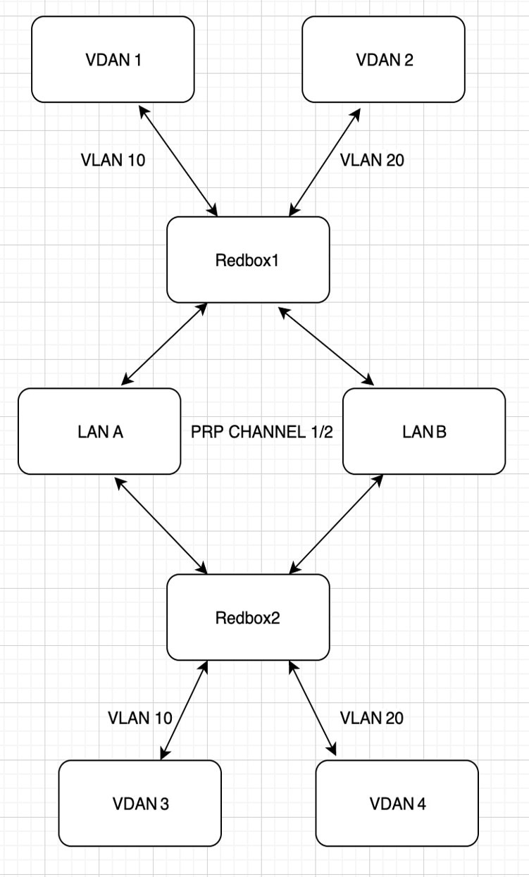
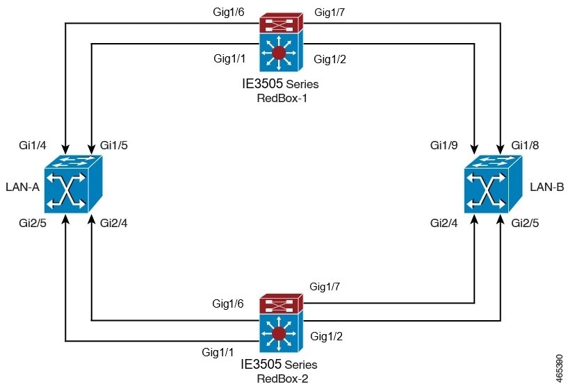
PRP channel or channel group is a logical interface that aggregates two Gigabit Ethernet interfaces (access, trunk, or routed) into a single link. In the channel group, the lower numbered Gigabit Ethernet member port is the primary port and connects to LAN-A. The higher numbered port is the secondary port and connects to LAN-B.
The PRP channel remains up as long as at least one of these member ports remains up and sends traffic. When both member ports are down, the channel is down. The maximum number of supported PRP channel groups per switch is 2, depending on the configured FPGA profile. For information about FPGA profile, see Configure FPGA Profile.
The interfaces that you can use for each group on each switch series are fixed, as shown in the following table.
|
PRP Channel Number |
Module |
Ports Interface |
|---|---|---|
|
PRP Channel 1 |
Base module with SFP ports |
GigabitEthernet1/1 and 1/2 |
|
PRP Channel 1 |
Base module with Copper (CU) ports |
GigabitEthernet1/4 and 1/5 |
|
PRP Channel 2 |
Base module with CU ports |
GigabitEthernet1/6 and 1/7 |
|
PRP Channel 2 |
8 port CU expansion module |
GigabitEthernet2/1 and 2/2 |
|
PRP Channel 2 |
8 port SFP expansion module |
GigabitEthernet2/1 and 2/2 |
|
PRP Channel 2 |
16 port CU expansion module |
GigabitEthernet2/1 and 2/2 |
|
PRP Channel 2 |
8 port Mix expansion module |
GigabitEthernet2/7 and 2/8 |
|
PRP Channel 2 |
16 port Mix expansion module |
GigabitEthernet2/15 and 2/16 |
|
PRP Channel Number |
Module |
|
|---|---|---|
|
PRP Channel 1 |
Base module with CU ports |
GigabitEthernet1/1 and 1/2 |
|
PRP Channel 1 |
Base module with CU ports |
GigabitEthernet1/4 and 1/5 |
|
PRP Channel 2 |
Base module with CU ports |
GigabitEthernet1/6 and 1/7 |
Mixed Traffic and Supervision Frames
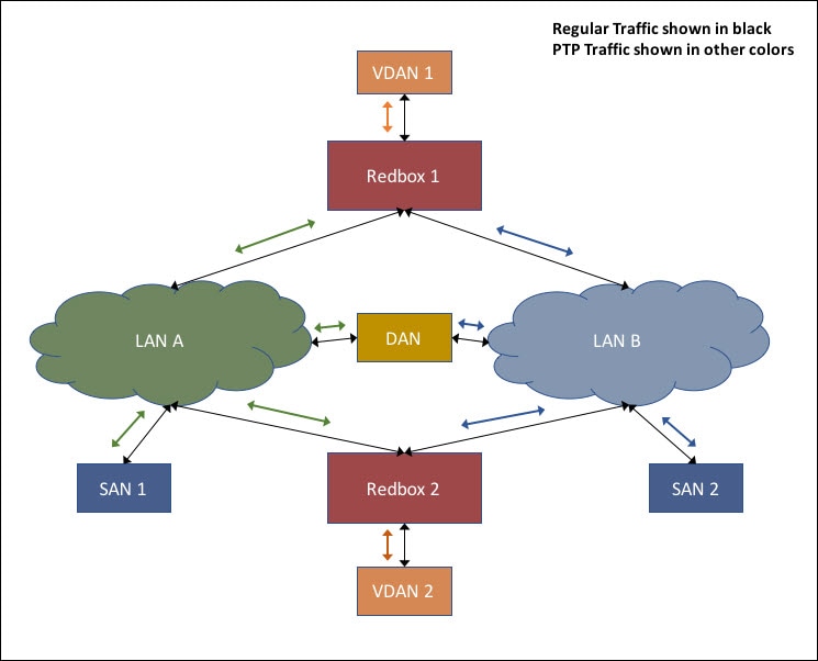
Traffic egressing the RedBox PRP channel group can be mixed, that is, destined to either SANs (connected only on either LAN-A or LAN-B) or DANs. To avoid duplication of packets for SANs, the switch learns source MAC addresses from received supervision frames for DAN entries and source MAC addresses from non-PRP (regular traffic) frames for SAN entries and maintains these addresses in the node table. When forwarding packets out the PRP channel to SAN MAC addresses, the switch looks up the entry and determines which LAN to send to rather than duplicating the packet.
A RedBox with VDANs needs to send supervision frames on behalf of those VDANs. For traffic coming in on all other ports and going out PRP channel ports, the switch learns source MAC addresses, adds them to the VDAN table, and starts sending supervision frames for these addresses. Learned VDAN entries are subject to aging.
You can add static entries to the node and VDAN tables as described in x. You can also display the node and VDAN tables and clear entries. See y and z.
VLAN Tag in Supervision Frame
Switches support VLAN tagging for supervision frames. PRP VLAN tagging requires that PRP interfaces be configured in trunk mode. This feature allows you to specify a VLAN ID in the supervision frames for a PRP channel.
 Note |
The IE3505 Series Switches support 512 VDAN/Node MAC addresses. The PRP Supervision VLAN-aware feature is not supported in the IE3505 Series Switches. |
For information on configuring the VLANs, see Configuring PRP Channel with Supervision Frame VLAN Tagging.
 Feedback