Product Overview
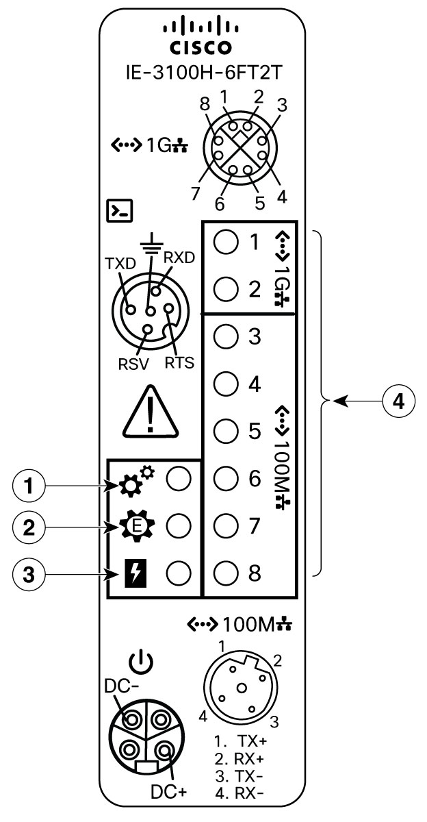
Cisco Catalyst IE3100H Heavy Duty Series Switch is a IP66/IP67 rated compact entry-level managed L2 switch. The switch is specifically designed as an I/O Network Switch for PLC-level connectivity, available in 8 Gigabit Ethernet (X-coded) or 2 Gigabit Ethernet (X-coded) + 6 Fast Ethernet (D-coded) M12 interface models. These switches cater to deployments including of automotive manufacturing, food and beverage, clean rooms or other industrial environments that are required to be cleaned regularly with harsh-chemicals and support a 24x7 production process.
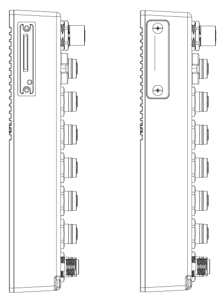
The switch is an enclosed type equipment, it can be wall mounted and deployed without a housing cabinet, under either indoor or outdoor environment with Pollution Degree 2.
Switch Models
|
Hardware Specifications |
IE-3100H-8T-E |
IE-3100H-6FT2T-E |
|---|---|---|
|
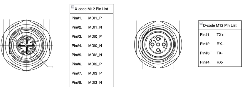
100-Mbps D-coded ports |
0 |
6 |
|
1-Gbps X-coded ports |
8 |
2 |
|
Removable storage |
SD card1 |
|
|
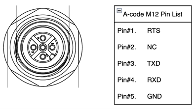
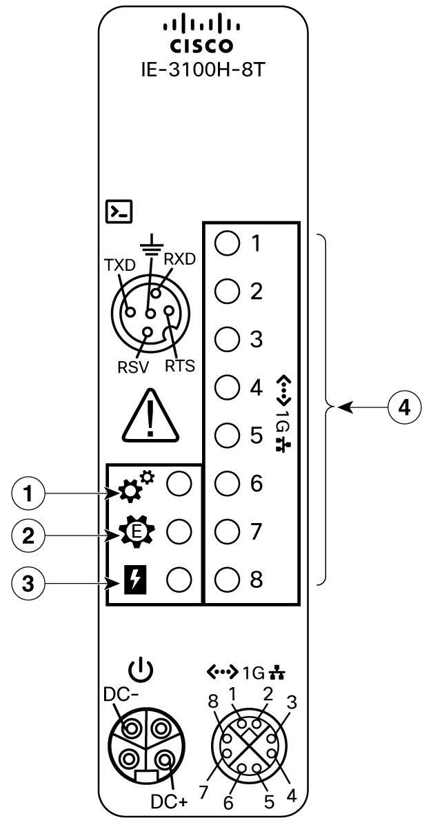
Console ports |
1x A-code M12 |
|
|
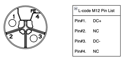
Power input (Marked Rating) |
12–48 VDC, 1.5 A |
|
|
Power Connector |
1xL-Code M12 |
|

 Feedback