G.8032 Ethernet Ring Protection

PDF

G.8032 Ethernet Ring Protection

G.8032 Ethernet Ring Protection

Want to summarize with AI?

Log in

Explains the G.8032 Ethernet Ring Protection feature that implements protection switching mechanisms for Ethernet layer ring topologies.


G.8032 Ethernet ring protection is a protection switching feature that

  • implements protection switching mechanisms for Ethernet layer ring topologies

  • uses the G.8032 Ethernet ring protection (ERP) protocol version 1, defined in ITU-T G.8032, and

  • provides protection for Ethernet traffic in a ring topology with non-Cisco devices.


ITU-T G.8032 Ethernet ring protection switching functionality

ITU-T G.8032 Ethernet ring protection switching functionality is a network protection mechanism that

  • provides loop avoidance,

  • uses learning, forwarding, and Filtering Database (FDB) mechanisms, and

  • ensures traffic flows continuously through all links except the Ring Protection Link (RPL).

RPL node types and functions

Loop avoidance in an Ethernet ring is achieved by ensuring traffic flows continuously through all links except the Ring Protection Link (RPL).

This is a list of RPL types (or RPL nodes) and their functions:

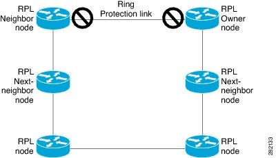
  • RPL owner: Responsible for blocking traffic over the RPL to prevent loops in the Ethernet traffic. There can be only one RPL owner in a ring.

  • RPL neighbor node: An Ethernet ring node adjacent to the RPL. It is responsible for blocking its end of the RPL under normal conditions. This node type is optional and prevents RPL usage when protected.

  • RPL next-neighbor node: Next-neighbor node is an Ethernet ring node adjacent to an RPL owner node or RPL neighbor node. It is mainly used for FDB flush optimization on the ring. This node is also optional.

The figure illustrates the G.8032 Ethernet ring topology.

Figure 1. G.8032 Ethernet ring topology
The G.8032 Ethernet ring topology illustrates the arrangement of nodes, including RPL neighbor and next-neighbor nodes, and their roles in Ethernet ring protection switching functionality.

R-APS control messages

R-APS control messages are ring coordination mechanisms that

  • coordinate switching the ring protection link (RPL) on and off between nodes on the ring

  • trigger when a failure occurs along the ring, sending R-APS Signal Failure (R-APS SF) messages in both directions from nodes adjacent to the failed link after they block the port facing the failed link, and

  • cause the RPL owner to unblock the RPL port upon receipt of this message.

Loop-free topology behavior

Note

A single link failure in the ring ensures a loop-free topology.


G.8032 ERP timers

G.8032 ERP timers are network management mechanisms that

  • prevent race conditions during network state changes

  • filter out intermittent faults and verify network stability, and

  • ensure proper sequencing of switching operations in Ethernet ring protection.

Timer types and configuration

The G.8032 protocol uses three main categories of timers:

  • Delay timers: Used by the Ring Protection Link (RPL) owner to verify that the network has stabilized before blocking the RPL. Note the following points about delay timers.

    • After a signal failure (SF) condition, a Wait-to-Restore (WTR) timer is used to verify that the SF is not intermittent.

    • The WTR timer can be configured by the operator. The default time interval is 5 minutes; the time interval ranges from 1 to 12 minutes.

    • After a force switch (FS) or a manual switch (MS) command is issued, a Wait-to-Block (WTB) timer is used to verify that no background condition exists.

      Note

      The WTB timer interval may be shorter than the WTR timer interval.

  • Guard timer: Used by all nodes when changing state; the guard timer blocks latent outdated messages from causing unnecessary state changes. The guard timer can be configured. The default time interval is 500 ms; the time interval ranges from 10 to 2000 ms.

  • Hold-off timers: Used by the underlying Ethernet layer to filter out intermittent link faults. The hold-off timer can be configured. The default time interval is 0 seconds; the time interval ranges from 0 to 10 seconds. Faults are reported to the ring protection mechanism only if this timer expires.