Best Practices for Deploying Multimode Bidirectional Pluggable Transceivers White Paper
Available Languages
Bias-Free Language
The documentation set for this product strives to use bias-free language. For the purposes of this documentation set, bias-free is defined as language that does not imply discrimination based on age, disability, gender, racial identity, ethnic identity, sexual orientation, socioeconomic status, and intersectionality. Exceptions may be present in the documentation due to language that is hardcoded in the user interfaces of the product software, language used based on RFP documentation, or language that is used by a referenced third-party product. Learn more about how Cisco is using Inclusive Language.
Value: Cisco QSFP-40/100-SRBD, QSFP-100G-SR1.2, and QDD-400G-SR4.2-BD (40/100/400G multimode bidirectional optics) let customers reuse duplex multimode fiber for migration from 10G short reach (SR) to 40G, 100G, and 400G.
Challenge: A fiber plant originally installed for 10G SR can often be reused for 40/100/400G multimode bidirectional optics, but it should be verified against the specific transceiver requirements, because these optics use 25 gigabaud (Gbaud) vertical-cavity surface-emitting lasers (VCSELs) and 50G pulse amplitude modulation 4-level (PAM4) per optical lane rather than the 10 Gbaud non-return-to-zero (NRZ) VCSELs used for the original application.
What fails in the field: Link flaps on these transceivers are usually physical-layer margin problems, not random module failures. Typical causes are too many mated connections for a 1.9 dB channel, contaminated end faces, wrong loss-test method, uncontrolled modal bandwidth at the longer wavelength used by these optics (~910 nm), back reflection, and multipath interference (MPI). Those mechanisms already existed on 10G SR; however, they did not matter as much. The same dirty connector, extra cassette, or 910 nm differential mode delay (DMD) penalty that 10G never noticed can close a PAM4 eye and flap the link.
Recommendations: Start with the existing plant originally installed and tested for 10GBASE-SR and verify it against the bidirectional transceiver’s application requirements before optics installation. Testing that supported 10GBASE-SR remains useful evidence of plant condition, but it does not by itself verify every parameter relevant to operation at 25 Gbaud. There are three takeaway recommendations for 40/100/400G multimode bidirectional optics:
● Number of optical connections. Design the cabling channel for no more than four mated pairs, excluding the transceiver ports, in line with the IEEE 802.3 Clause 150.10.1 fiber optic cabling model.
● Quality of the connections and cleanliness. Inspect-clean-inspect every LC and MPO end face, including the module receptacle, to IEC 61300-3-35 before every mate. Contamination is the leading cause of insertion loss, back reflection, and intermittent flaps on VCSEL links for these optics. For trunk cable MPO termination, a US Conec MTP or equivalent quality connector is recommended to avoid potential back-reflection and stability issues.
● Measure optical channel loss. Certify the channel with an encircled flux (EF) compliant optical loss test set (OLTS) using the 1-jumper reference at 850 nm, and compare the result with the transceiver application budget (1.9 dB). A TIA “pass” can still be a fail for these bidirectional optics.
The 40/100/400G bidirectional multimode optics product family
QSFP-40/100-SRBD, QSFP-100G-SR1.2, and QDD-400G-SR4.2-BD are duplex (or parallel duplex) bidirectional optics. In this paper, “bidirectional multimode optics” refers collectively to these product families; where a product-specific distinction matters, the paper uses SRBD, SR1.2, or SR4.2-BD. They are not single-fiber access “A/B pair” modules. Each fiber carries transmit and receive at two different wavelengths, isolated by a passive Wavelength-Division Multiplexing (WDM) filter in the module. Both ends of a link use the same SKU; there is no upstream/downstream pairing.
Table 1. 40/100/400G bidirectional multimode optics relevant information
| Product ID |
Form factor |
Rate |
Optical arrangement |
VCSEL class |
Connector |
Fiber |
| QSFP- 40/100- SRBD |
QSFP28 |
40G or 100G |
40G: 2x 20G NRZ 100G: 2x 50G PAM4, 850/910 nm |
40G: ~20 Gbaud NRZ; 100G: ~26 Gbaud PAM4 |
Duplex LC UPC |
OM3/OM4/ OM5 |
| QSFP- 100G-SR1.2 |
QSFP28 |
100G only |
2x 50G PAM4, 850/910 nm |
26 Gbaud PAM4 (25G-class VCSEL) |
Duplex LC UPC |
OM3/OM4/ OM5 |
| QDD-400G-SR4.2-BD |
QSFP-DD |
400G or 4x 100G |
8x 50G PAM4 on 4 fiber pairs, 850/910 nm (4 pairs) |
26 Gbaud PAM4 (25G-class VCSEL) |
MPO-12 UPC |
OM3/OM4/ OM5 |
Always confirm platform and software support in the Optics-to-Device Compatibility Matrix, and optics-to-optics mapping in the Interoperability Matrix (see the References section).
Optical transmission is vulnerable to chromatic dispersion, modal dispersion, polarization-mode dispersion, and noise. Short-reach Cisco® 40/100/400G multimode bidirectional optics fail on the same physical mechanisms already present on 10G SR. What has changed is the laser and the modulation.
Reusing a duplex LC multimode plant originally installed for 10GBASE-SR is geometrically valid (the connectors and fiber type still match) and can be a practical migration path. It still requires verification of connection count, cleanliness, loss discipline, 910 nm bandwidth, and back reflection, which become first-order at 25 Gbaud.
Table 2. Why the same fiber plant behaves differently
| Item |
10GBASE-SR (10G VCSEL) |
Cisco 40/100/400G bidirectional multimode optics (25G VCSEL) |
| Optical lane |
10 Gbaud NRZ |
25 Gbaud PAM4 |
| Bits per symbol |
1 |
2 |
| Unit interval |
~97 ps |
~38–39 ps |
| Receiver eyes |
One large 2-level eye diagram |
Three stacked PAM4 eyes (~one third the NRZ vertical opening) |
| Forward Error Correction (FEC) |
None (Bit Error Ratio (BER) 1E-12 on the wire) |
Yes (onboard or host KP4) Pre-FEC BER designed at 2.4E-4 |
| Effective Modal Bandwidth (EMB) specified for the wavelength in use |
Yes (850 nm) |
Partial (850 nm yes; ~910 nm not specified for OM3/OM4) |
| What “receive power in spec” proves |
Usually enough |
Not enough (eye can be closed) |
Four reasons a 25 Gbaud module requires careful verification of an existing 10G plant:
● The bit (symbol) is about 2.5x shorter. Modal delay that occupied a third of a 10G unit interval is approximately one full symbol at 26.6 Gbaud. Pulse overlap that 10G SR absorbed as a slightly fuzzy NRZ eye becomes inter-symbol interference in the middle PAM4 decision threshold. Cisco’s white paper “Understanding FEC and Its Implementation in Cisco Optics” (see the References section) makes the general point: at higher speed the receiver filter must be wider and therefore admits more noise. On multimode fiber the same statement applies to modal dispersion: the fiber did not get faster, the symbol did.
● PAM4 has far less amplitude margin than 10G NRZ. Four optical levels split the same extinction into three eyes. Relative to NRZ, that is on the order of 9.5 dB of Signal-to-Noise Ratio (SNR) penalty (20·log10(3)) before you add fiber. A 0.3 to 0.5 dB dirty LC or a modest multipath-interference term that never produced Cyclic Redundancy Check (CRC) errors on 10G SR will drive pre-FEC BER into uncorrectable events on SRBD, SR1.2, and SR4.2. That is why these links flap rather than sitting at a constant low error rate: FEC is already working at the edge of its coding gain.
● The 25G VCSEL die is less forgiving of light that comes back. Reaching 25 GHz-class modulation requires smaller oxide apertures and higher current density than 10G VCSELs. Optical feedback from a connector, air gap, or crushed contamination increases relative intensity noise, encourages mode hopping, and adds jitter. 10G VCSELs were relatively tolerant of the 20 to 35 dB return loss of a typical multimode UPC pair. 25 Gbaud VCSELs are not. Cleanliness and connection count in this paper are reflection problems, not only loss problems.
● The specification moved from power to eye closure. 10G SR field practice was Digital Optical Monitoring (DOM) or a power meter. 25 Gbaud PAM4 transmitters are qualified with TDECQ (transmitter and dispersion eye closure quaternary). The fiber plant adds penalty to that closure. Enough photons can still fail the link. Having the receive power in spec does not mean the link will stay up.
In multimode fiber, a pulse propagates as many spatial modes. Higher-order modes take a longer path than lower-order modes. The resulting spread in time of flight is modal dispersion. It broadens the pulse, reduces amplitude, and causes inter-symbol interference. A 10G VCSEL’s ~97 ps NRZ eye can absorb a surprising amount of this. A 25 Gbaud PAM4 eye cannot.
These transceivers do not operate only at 850 nm. The second lane sits near 910 nm, where OM3/OM4 effective modal bandwidth is not specified. OM5 controls bandwidth further into that window; standard OM3/OM4 does not. Do not assume that a successful 850 nm 10GBASE-SR test proves the fiber at 910 nm.
Each bidirectional module contains a WDM diplexer so that 850 nm and 910 nm optical channels share the fiber. Any reflection from a connector, air gap, crack, or contamination returns toward the laser and toward the local receiver through finite filter isolation.
That path existed with 10G VCSELs, but it is worse at 25 Gbaud: the cavity is more feedback-sensitive, the symbol is shorter (so a given fiber delay is a larger fraction of a unit interval), and PAM4 has no spare vertical margin for the resulting Relative Intensity Noise (RIN) and MPI.
25 Gbaud VCSEL-based PAM4 receivers are sensitive to:
● Discrete reflections (poor physical contact, APC/UPC mismatch, unseated MPO)
● MPI from two or more reflections that recombine with a time delay, producing a noisy, time-varying eye signal
● Modal noise when connector offsets and contamination change the mode fill
The symptom is characteristic: DOM receive power is “in range,” yet the link CRC-storms or flaps under traffic, after a cable move, or as temperature changes. Power meters report average power. They do not report MPI.
Multimode UPC connectors typically return 20 to 35 dB. That is adequate if the plant is short, clean, and has few mates. It is not adequate if ferrules are dirty, not fully seated, or concatenated through extra couplers. Every additional mated pair is both a loss event and a reflection event.
Fiber plant requirements for 25 Gbaud bidirectional optics
At 10G SR, IEEE still allocated about 1.5 dB to connectors at maximum reach, but unused dispersion penalty on a typical 30 to 70 m data center run was large, the NRZ eye was wide, and there was no FEC cliff. Extra cassettes often just worked on 10G VCSEL links.
At 100/400G with these bidirectional optics, the 25 Gbaud PAM4 penalty allocation is already spent on the VCSEL and the fiber DMD. What remains of the budget is connectors.
Cisco data sheets allocate 1.5 dB of the 1.9 dB total to connections and splices, in line with IEEE (1.5 dB connection allocation plus 3.5 dB/km fiber attenuation at 850 nm).
Fiber itself consumes only a small portion of the total optical power budget, as shown in Table 3.
Table 3. Loss available for connectors (some examples)
| Reach |
Fiber loss at 3.5 dB/km |
Remaining for connectors (from 1.9 dB) |
| 70 m |
0.25 dB |
~1.65 dB |
| 100 m |
0.35 dB |
~1.55 dB |
| 150 m |
0.53 dB |
~1.37 dB |
Connection count is not a cabling-standard trivia item.
Compared with a 10G VCSEL, each added mated pair on a 25 Gbaud VCSEL is not only loss but also a reflection. 10G largely ignored that reflection. 25 Gbaud cannot.
Cisco 100/400G multimode bidirectional optics are specified to the IEEE fiber optic cabling model.
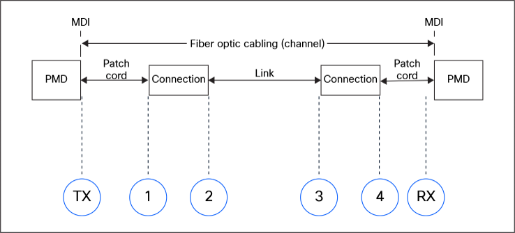
Fiber optic cabling model (excerpt from IEEE Std 802.3, Clause 150)
That model matches how Cisco and cabling partners have tested channels for these bidirectional optics. The Cisco and Berk-Tek Leviton Technologies Application Note on Cisco QSFP BiDi transceivers (see the References section) used a typical data center switch-to-switch topology:
● LC patch cord → MTP-LC cassette → trunk → cassette → LC patch cord.
● Four connections. The connection count does not include the mates at the QSFP modules.
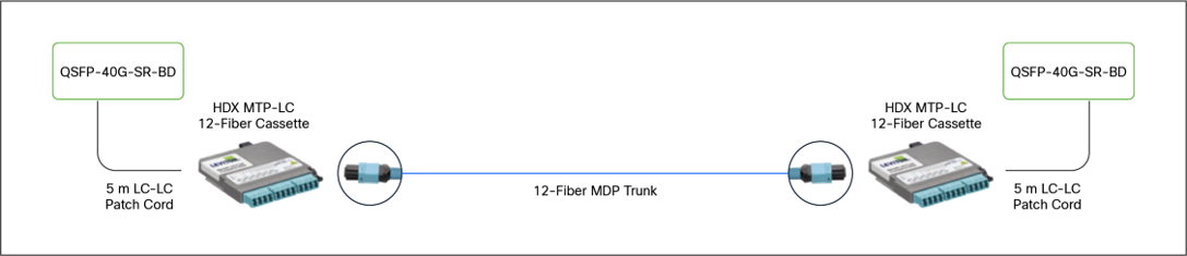
Switch-to-switch topology
LC connection points lose less than MPO ones and therefore support more patching for a given budget—but the budget is still 1.5 dB. Extra patch panels provide flexibility, not free optical margin.
A 10G plant is typically installed and tested to TIA-568. That standard allows 0.75 dB per mated pair. Four such pairs are 3.0 dB. These optics have 1.5 dB for all connectors combined. The cabling standard and the transceiver application budget are different references. A plant can meet the cabling standard and support 10G VCSEL operation while still requiring application-specific verification for the bidirectional multimode optics.
Table 4. Connector pair loss per grade
| Connector grade (per mated pair) |
Pairs that fit in 1.5 dB |
Field meaning |
| TIA-568 maximum 0.75 dB |
2 |
Generic cabling max. Too pessimistic to design to, too loose to test to if you check only “TIA pass.” |
| Conservative installed LC/MPO, 0.50 dB |
3 |
Typical mixed plant with average jumpers. |
| Low-loss factory LC/ MTP Elite, 0.35 dB |
4 |
Standard bidirectional design target. |
Count every place two ferrules meet:
● Equipment cord to patch-panel/cassette LC or MPO
● Cassette MPO to trunk MPO
● Trunk-to-trunk coupler or adapter plate
● Cross-connect jumper at a second row of panels
● Any LC coupler, media converter, or “gender changer”
● MPO-to-LC breakout cassette (two optical interfaces: MPO in, LC out)
● MPO-to-4×LC hydra (MPO mate plus four LC mates on that path)
Cisco’s white paper “Six Considerations When Planning Data Center Network Upgrades” (see the References section) lists the operational reason duplex LC bidirectional optics exist: LC is easier to clean and inspect, has less insertion-loss variability, and is less likely to be contaminated than MPO. That advantage disappears if nobody inspects.
Industry data continues to show that contaminated end faces are the leading cause of optical downtime. For 10G VCSELs the usual result was a few extra tenths of a dB and a link that stayed up.
For 25 Gbaud VCSELs the same particle has worse effects than simple loss:
● A particle on the core blocks power (loss) that the 1.9 dB budget cannot spare.
● The same particle, crushed between ferrules, creates an air gap (loss and a strong reflection into a feedback-sensitive 25 Gbaud VCSEL).
● On MPO, one crushed particle can seed debris across the 250-micron fiber pitch and take down four 100G breakout legs.
● Reflections increase VCSEL RIN and MPI; PAM4 runs out of FEC and the link flaps rather than sitting at a constant low error rate the way 10G SR often did.
Inspect, clean if needed, inspect, then connect: Never mate a dust cap to a port and assume the ferrule is clean. Never clean “because it is good practice” without inspecting; dry cleaning a clean UPC can add residue. Never look into a live fiber.
Apply this practice to:
● Both LC ferrules on every jumper
● Both MPO ferrules on every trunk, hydra, and cassette
● The transceiver receptacle (LC or MPO) on SRBD, SR1.2, and SR4.2-BD
● Alignment pins and pin holes on MPO (debris in a guide hole misaligns all fibers)
Acceptance criteria and equipment
Grade end faces to IEC 61300-3-35 (Ed. 3:2022 is current) using an automated probe. Pass/fail is based on defects and scratches in the core and cladding zones. Do not accept a “looks pretty clean” judgment based on a laptop camera.
IEC 61300-3-35 Ed. 3 still requires technicians to inspect the full MPO ferrule and remove loose particles that can migrate into Zone A/B. Particles that remain after several cleaning attempts on the outer contact zone may be treated as embedded; they must not be in the core.
Table 5. Connector cleanliness and equipment
| Task |
Equipment |
| Inspect LC |
400x/200–400x probe, 1.25 mm tip, IEC analysis (examples: VIAVI P5000i, FiberChek; EXFO FIP; Fluke FI-3000) |
| Inspect MPO-12 |
Dedicated MPO/MTP tip; inspect all 12 fibers and the pin field, not one “representative” fiber |
| Inspect bulkheads |
Bulkhead adapter tips for LC and MPO (male/female as required) |
| Clean LC |
1.25 mm click cleaner; lint-free stick plus residue-free solvent only if dry clean fails |
| Clean MPO |
MPO cassette/wide-fabric cleaner that wipes the full MT ferrule in one pass; separate pin/hole sticks |
| Protect |
Keep dust plugs in until the moment of inspection; do not set ferrules on clothing or tile |
One-click cleaners are for one click. Repeated clicking on a dirty MPO smears contamination into the cores.
If a link flaps after a cable is reseated, assume contamination or an incomplete LC or MPO latch before assuming a failed optic. Inspect both ends and both bulkheads. If the ferrule shows pits or scratches in Zone A, replace the jumper; cleaning will not restore glass that has been crushed.
There are two different pass/fail criteria. Do not treat them as the same number.
Table 6. Optical channel loss criteria
| Test |
Typical limit |
Meaning |
| TIA-568.3/ISO 11801 channel |
~0.75 dB × N connectors + fiber |
Cabling warranty style limit. Can be 2 to 3 dB on a four-connector channel. |
| Cisco/IEEE application for these bidirectional optics |
1.9 dB total, of which 1.5 dB is connectors |
What the transceiver can tolerate. |
A channel can pass TIA-568 and still require additional verification for these bidirectional optics.
Knowledge of the link loss is necessary but not sufficient—especially on 25 Gbaud PAM4. A 1.2 dB channel with a bad 910 nm DMD or a single highly reflective connector can still flap even though the same measurement would have been a comfortable 10G SR pass. After a loss pass, if the link still errors, troubleshoot reflections, polarity, FEC, and fiber type as described in the following test method.
● Follow ANSI/TIA-526-14-C/IEC 61280-4-1 for multimode installed-plant attenuation.
● Launch condition: Encircled Flux (EF) at 850 nm on 50-micron fiber. A non-EF source (random LED, or a transceiver used as a light source) can bias the reading by several tenths of a dB—enough to pass a bad plant or fail a good one.
● Reference method: 1-jumper (one-cord). This includes the loss of the first and last connections, which is how the channel is used.
● Wavelength: 850 nm minimum. 1300 nm is optional and is not a substitute for 850 nm. Field OLTS units generally cannot test at 910 nm. The 850 nm loss is the installed-plant metric, but it does not establish EMB at 910 nm.
● Direction: Test both fibers (or all eight active MPO fibers) in both directions if the instrument supports it. These optics use both fibers as Tx and Rx.
● Test Reference Cords (TRCs): Verify TRCs: multimode TRC verification target is typically ≤0.10 dB. Bad TRCs are the largest source of false fails.
● EF-compliant OLTS (main + remote), 850 nm (and 1300 nm), LC duplex adapters. Examples of the class of instrument are Fluke CertiFiber Pro and FiberInspector, EXFO MaxTester OLTS and FTB, and VIAVI SmartClass Fiber OLTS-85. The brand is not the requirement; EF compliance and a 1-jumper workflow are.
● EF-compliant TRCs for LC duplex (SRBD/SR1.2) and, for SR4.2, MPO-12 UPC TRCs plus MPO-to-LC fanouts if testing after a cassette.
● IEC 61300-3-35 inspection probe with LC and MPO tips.
● Cleaning kit for LC 1.25 mm and MPO-12.
1. Inspect and clean the TRCs and bulkhead adapters before you set the reference.
2. Set reference with the 1-jumper method at 850 nm. Do not disconnect the TRC from the source after referencing.
3. Connect into the permanent link or channel exactly as the optics will use it (include the equipment jumpers if you are certifying the channel).
4. Compare to 1.9 dB.
For MPO-12 SR4.2, test the eight active fibers (typically positions 1–4 and 9–12 on a 12-fiber ferrule; 5–8 are unused). Polarity must be Method B for Ethernet-style parallel plants unless the cassette design states otherwise. A polarity error presents as Rx power on the wrong lanes or one breakout leg down.
A note on Module Power Monitors (DOM)
DOM is a live health check, not a certifier. Typical accuracy is about ±3 dB. Tx and Rx power readouts cannot be used to derive the optical channel loss.
How to read and interpret Tx and Rx power monitors:
● Rx below minimum: High loss, dirty connector, broken fiber, polarity error, or a dead Tx. Measure the plant with an OLTS.
● Rx in range with high CRC, high pre-FEC BER, or flaps: MPI, modal dispersion, contamination that reflects more than it attenuates, FEC mismatch, or one of the two wavelengths degraded. Do not stop at “power is good.” On 25 Gbaud PAM4 this is the most common false all-clear.
● Rx near maximum on a very short jumper is rarely a problem for these multimode receivers (overload is typically around +4 to +5 dBm). Inspect for a missing attenuator only if an unusual high-power source was introduced.
Procedure to set up bidirectional multimode optics on an existing 10GBASE-SR link
A plant that carried 10G SR is a valid starting point for bidirectional optics operating at 25 Gbaud, but it should be verified against the optics’ application requirements.
Use this sequence before declaring the optics at fault.
1. Confirm pairing and FEC. Use the same product ID at both ends: SRBD to SRBD, SR1.2 to SR1.2, or SR4.2-BD to 4×SR1.2. Do not mix QSFP-40/100-SRBD with QSFP-100G-SR1.2. Enable host KP4 FEC on SR1.2 and SR4.2. If one end is 40G-SR-BD, lock the dual-rate module to 40 Gb.
2. Confirm platform and software support in the Optics-to-Device Compatibility Matrix before you insert the modules.
3. Confirm the media. Use OM3, OM4, or OM5 50-micron fiber only, and UPC/PC polish only. Do not use APC (green) connectors, OM1/OM2, or mode-conditioning patch cords.
4. Count mated pairs in the existing 10GBASE-SR plant. Walk every place where two ferrules meet. The design limit is four mated pairs in the cabling channel, excluding the two transceiver ports (IEEE Std 802.3 Clause 150.10.1). Prefer two. Extra 10G patch panels can provide flexibility, but they do not add optical margin. If you count more than four, redesign the channel before you install bidirectional optics.
5. Inspect, clean if needed, inspect, then connect. Grade every LC and MPO end face and both module receptacles to IEC 61300-3-35. Include MPO alignment pins and holes. Never assume a dust cap means a clean ferrule. Never look into a live fiber.
6. Verify channel loss against the transceiver application budget and the applicable cabling requirements. Use an EF-compliant OLTS, 1-jumper reference, 850 nm, both fibers (or the eight active MPO fibers for SR4.2). Compare with 1.9 dB. A TIA pass is useful evidence but does not by itself verify the application for these bidirectional optics. Do not use optics Tx and Rx power monitor readouts as a loss meter, a single-mode OLTS on 50-micron multimode fiber, or the pluggable as a light source.
7. Connect the optics the way the channel will run. Duplex LC uses standard A-to-B polarity. MPO-12 SR4.2 typically uses Method B in Ethernet plants unless the cassette design states otherwise. Fully seat and latch LC and MPO; a half-seated MPO is a reflector.
8. Bring the link up and treat DOM as a health check only. Record Tx power, Rx power, temperature, and voltage. Tx/Rx in range does not by itself verify the plant: DOM accuracy is about ±3 dB, and average power does not show MPI or eye closure.
9. Check errors, not only “link up.” Watch CRC, pre-FEC BER, and flaps under traffic. If Rx is in range and the link still flaps, treat it as MPI, 910 nm modal bandwidth, contamination, polarity, or FEC mismatch.
10. Change one variable at a time. Use a known-good jumper, a known-good module, or a short direct interconnect. RMA last, and only after FEC, cleanliness, connection count, and the 1.9 dB application-budget loss test are closed.
Cisco Transceiver Modules white papers (listing): https://www.cisco.com/c/en/us/products/interfaces-modules/transceiver-modules/white-paper-listing.html
Cisco 100GBASE QSFP-100G Modules Data Sheet. Link loss budget for QSFP-40/100-SRBD and QSFP- 100G-SR1.2; optical characteristics. https://www.cisco.com/c/en/us/products/collateral/interfaces-modules/transceiver-modules/datasheet-c78-736282.html
Cisco 400G QSFP-DD Cable and Transceiver Modules Data Sheet. QDD-400G-SR4.2-BD reach, MPO-12 UPC, 12W, 4x 100G breakout to QSFP-100G-SR1.2. https://www.cisco.com/c/en/us/products/collateral/interfaces-modules/transceiver-modules/datasheet-c78-743172.html
Cisco 40GBASE QSFP Modules Data Sheet. QSFP-40G-SR-BD loss budget and allowable connector loss vs. distance. https://www.cisco.com/c/en/us/products/collateral/interfaces-modules/transceiver-modules/data_ sheet_c78-660083.html
Cisco 100Gbps QSFP100 SR1.2 BiDi Pluggable Transceiver At-a-Glance. Interoperability with SR4.2; non-interoperation with QSFP-40/100-SRBD. https://www.cisco.com/c/en/us/products/collateral/interfaces-modules/transceiver-modules/100gbps-bidi-plug-transceiver-aag.html
Cisco 40/100Gb QSFP100 BiDi Pluggable Transceiver At-a-Glance. Dual-rate operation, 850/910 nm, onboard FEC, PAM4 in 100G mode. https://www.cisco.com/c/en/us/products/collateral/interfaces-modules/transceiver-modules/at-a-glance-c45-740242.pdf
Understanding the Differences Between OM4 and OM5 Multimode Fiber (Cisco white paper). EMB, DMD, and uncontrolled OM4 bandwidth at non-850 nm wavelengths. https://www.cisco.com/c/en/us/products/collateral/interfaces-modules/transceiver-modules/diff-om4-om5-multimode-fiber-wp.html
Understanding FEC and Its Implementation in Cisco Optics (Cisco white paper). Modal dispersion, KP-FEC RS (544,514), host vs. module FEC. https://www.cisco.com/c/en/us/products/collateral/interfaces-modules/transceiver-modules/implementation-optics-wp.html
Craig Pasek and Pat Chou, Don’t Mix Up Your FECs, Cisco SP360 Service Provider blog. https://blogs.cisco.com/sp/dont-mix-up-your-fecs
What Are Breakouts and How Do You Use Them? (Cisco white paper). QDD-400G-SR4.2-BD MPO-12 breakout; SR-BD not breakout-capable. https://www.cisco.com/c/en/us/products/collateral/interfaces-modules/transceiver-modules/whitepaper-c11-744077.html
Six Considerations When Planning Data Center Network Upgrades (Cisco white paper). BiDi reuse of duplex LC; LC vs. MPO cleanliness and loss; enhanced OM4 for BiDi wavelengths. https://www.cisco.com/c/en/us/products/collateral/interfaces-modules/transceiver-modules/white-paper-c11-743230.html
Berk-Tek Leviton Technologies’ Connectivity Performance with Cisco QSFP BiDi Transceivers (Cisco and Berk- Tek Leviton Technologies Application Note). Four-connection Configuration A; connection count excludes QSFP mates; 910 nm bandwidth not specified for OM3/OM4. https://www.cisco.com/c/dam/en/us/products/interfaces-modules/transceiver-modules/berk-tek-leviton-technologies.pdf
400G BiDi MSA, 400G-BD4.2 Technical Specification; IEEE Std 802.3cm (400GBASE-SR4.2), Clause 150. 1.5 dB connection allocation; EMB at 850/918 nm; channel insertion loss.
400GBASE-SR4.2 Application Overview. Valerie Maguire, TIA Fiber Optics Tech Consortium. https://www.tiafotc.org/ieee-802-3-ethernet-standards-update/multimode-standards-update/400gbase-sr4-2/
Troubleshoot Link Flap Issue on Nexus 9000 (Cisco Troubleshooting TechNotes). https://www.cisco.com/c/en/us/support/docs/switches/nexus-9000-series-switches/221572-troubleshoot-link-flap-issue-on-nexus-90.html
Standards for fiber plant testing (non Cisco): IEC 61300-3-35 (end-face inspection); IEC 61280-4-1 and ANSI/TIA- 526-14-C (MMF attenuation, encircled flux); ANSI/TIA-568.3 (cabling limits—do not substitute for the transceiver budget).
Tools:
● Cisco Optics-to-Device Compatibility Matrix, https://tmgmatrix.cisco.com/
● Optics-to-Optics Interoperability, https://tmgmatrix.cisco.com/iop
● Cisco Optics, https://www.cisco.com/go/optics