Cisco Compute Intersight Hardening Guide White Paper
Available Languages
Bias-Free Language
The documentation set for this product strives to use bias-free language. For the purposes of this documentation set, bias-free is defined as language that does not imply discrimination based on age, disability, gender, racial identity, ethnic identity, sexual orientation, socioeconomic status, and intersectionality. Exceptions may be present in the documentation due to language that is hardcoded in the user interfaces of the product software, language used based on RFP documentation, or language that is used by a referenced third-party product. Learn more about how Cisco is using Inclusive Language.
| Document summary |
Prepared for |
Prepared by |
| V2.2 |
Cisco Field |
Aaron Kapacinskas |
| Changes |
||
| Added Appendix D – USB BIOS Install boot procedure |
||
| Added Appendix E – TPM and TAM details for secure boot |
||
| Added Appendix F – Microchip tri-mode disk controller details |
||
| Added information about TPM self-tests |
||
| Added additional information around expired secure boot certificates |
||
| Added some updates to PQC |
||
| Added MFA for Intersight login |
||
This document contains confidential material that is proprietary to Cisco Systems, Inc. The materials, ideas, and concepts contained herein are to be used exclusively to assist in the configuration of Cisco® hardware and software solutions.
The documentation set for this product strives to use bias-free language. For purposes of this documentation set, bias-free is defined as language that does not imply discrimination based on age, disability, gender, racial identity, ethnic identity, sexual orientation, socioeconomic status, and intersectionality. Exceptions may be present in the documentation due to language that is hardcoded in the user interfaces of the product software, language used based on standards documentation, or language that is used by a referenced third-party product.
All information in this document is provided in confidence and shall not be published or disclosed, wholly or in part to any other party without Cisco’s written permission.
We recommend reviewing the Cisco UCS® release notes, installation guide, and user guide before proceeding with any configuration. Please contact Cisco Technical Assistance Center (Cisco TACor your Cisco representative if you need assistance.
Cisco Intersight® is a Software-as-a-Service (SaaS) cloud-based infrastructure lifecycle management platform or an on-premises appliance-based device that delivers simplified deployment, monitoring, and support of a Cisco Unified Computing System™ (Cisco UCS®). Systems managed with Intersight run in Intersight Managed Mode (IMM) or in standalone mode after being claimed by Intersight for management. Cisco Intersight can be used for both first-time deployment and management of UCS components and post-UCSM deployment management through a multifactor claim process.
Cisco Intersight is a cloud-operations platform that consists of modular capabilities for advanced infrastructure and workload optimization. Cisco Intersight infrastructure services include the deployment, monitoring, management, and support of your physical and virtual infrastructure. It supports Cisco Unified Computing System (Cisco UCS), myriad other Cisco networking offerings, and other third-party Intersight-connected targets. This guide is specific to UCS C-series, B-series, and X-series models.
This guide will focus on the security-hardening aspects of the Intersight Software-as-a-Service (SaaS) offering along with the on-premises version (Private Virtual Appliance [PVA] and Connected Virtual Appliance [CVA]) and its integration with Cisco UCS. The Cisco Intersight Connected Virtual Appliance software can be deployed on premises, allowing users to take advantage of the SaaS functionality. The Private Virtual Appliance can be deployed on premises with further security restrictions. For the remainder of this document, the term “Intersight” refers to all deployment modes unless explicitly stated otherwise.
We begin with Cisco’s development and design methodology and the various federally and internationally recognized certifications that validate this process. The guide will cover how the service is architected to secure system and service access, data transfer, and management. Regional redundancy and privacy will be explained, as well as the various user and system protections that are enabled through encryption, RBAC, segmentation, and policy.
At the core of Cisco’s UCS platform and Intersight offerings lies a development philosophy centered on proactive security measures. With an approach designed for preemptive threat mitigation and continuous enhancement, Cisco leverages in-house technologies and research to fortify its system architecture against emerging threats. Incorporating robust industry practices and adhering to stringent security protocols, the UCS and Intersight platforms are built to meet the highest standards of security certifications, ensuring compliance with regulatory frameworks, and assuring customers of a resilient and safeguarded infrastructure. Moreover, the management features embedded within the solution provide administrators with comprehensive tools for monitoring, auditing, and controlling access, enabling proactive threat identification and rapid response to potential security breaches.
In addition to its development and certification framework, Cisco UCS utilizes advancements in confidential computing and secure storage to keep user applications and data protected. Implementing NIST-approved encryption techniques, secure boot processes, and hardware-based isolation mechanisms, UCS ensures data confidentiality, integrity, and availability throughout its lifecycle. Through secure storage solutions and federally certified secure interfaces, users leverage the UCS platform confidently, knowing that their data remains protected against unauthorized access. This white paper discusses the implementation of these features, demonstrating how UCS meets and exceeds the security and accountability requirements in today’s enterprise environments.
For a general overview of UCS-based security, see the white paper here:
Cisco Compute Security Overview White Paper - Cisco.
The Cisco Secure Development Lifecycle – CSDL
Cisco products and components are developed, integrated, and tested using the Cisco Secure Development Lifecycle (CSDL). Secure product development and deployment h several components, ranging from following specified design and development practices, to testing their implementation, to providing customers with a set of recommendations for deployments that maximize the security of their system.
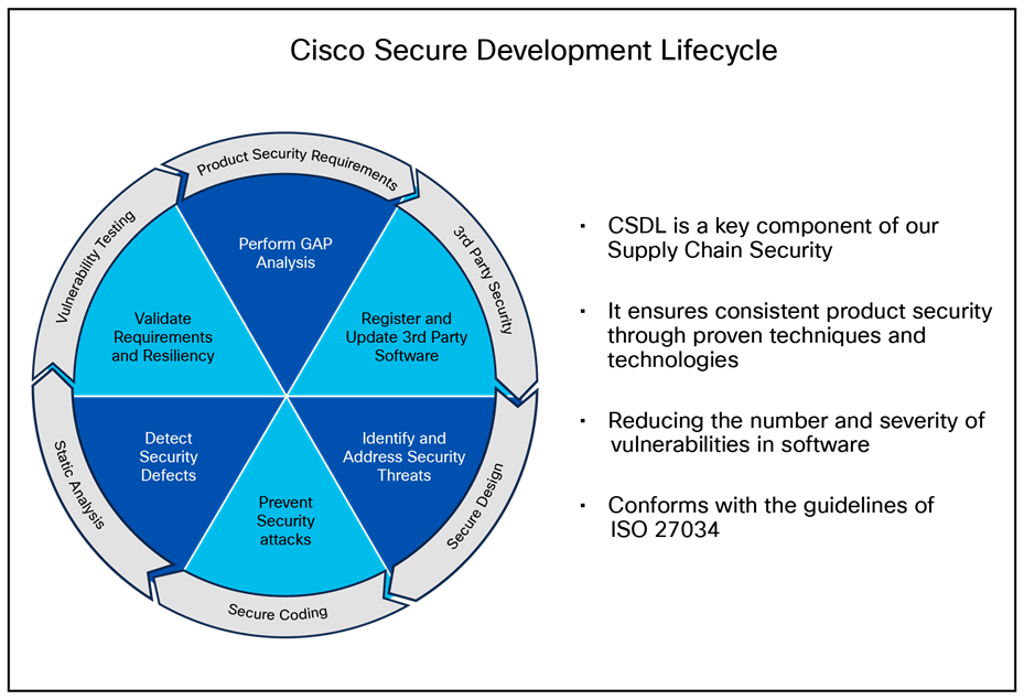
The Cisco Secure Product Development Lifecycle
A poor product design can open the way to vulnerabilities. The CSDL is designed to mitigate these potential issues. At Cisco, our secure-design approach requires two types of considerations:
● Design with security in mind
● Use threat modeling to validate the design’s security
Designing with security in mind is an ongoing commitment to personal and professional improvement through:
● Training
● Applying Product Security Baseline (PSB) design principles
● Considering other industry-standard secure-design principles
● Being aware of common attack methods and designing safeguards against them
● Taking full advantage of designs and libraries that are known to be highly secure
● Protecting all potential entry points
Cisco also reduces design-based vulnerabilities by considering known threats and attacks:
● Follow the flow of data through the system
● Identify trust boundaries where data may be compromised
● Based on the data flow diagram, generate a list of threats and mitigations from a database of known threats, tailored by product type
● Prioritize and implement mitigations to the identified threats
The goal of this effort is to enforce a set of security processes and ensure a security mindset at every stage of development:
● Secure design
● Secure coding
● Secure analysis
● Vulnerability testing
● Secure deployments
Each iteration of the product’s development addresses needs for ongoing security fixes and general feature enhancements that include security components (new deployment models, changes in management, partner onboarding, etc.). At every stage of development, the product(s) undergo potential enhancements relative to findings and new features.
● The system is configured in the Quality-Assurance (QA) testing stage to accommodate the relevant settings identified above and run through a typical deployment test.
● The result is a validated set of best practices for security and is communicated through the CSDL process and exposed in the documentation.
CSDL product adherence methodologies
Cisco CSDL adheres to Cisco Product Development Methodology (PDM), ISO/IEC 27034, and ISO 9000 compliance requirements. The ISO/IEC 27034 standard provides an internationally recognized standard for application security. Details for ISO/IEC 27034 can be found here. The ISO 9000 family of quality management systems standards is designed to help organizations ensure that they meet the needs of customers and other stakeholders while meeting statutory and regulatory requirements related to a product or service. ISO 9000 details are here.
The CSDL process is not a one-time approach to product development. It is recursive, with vulnerability testing, penetration testing, and threat modelling added to subsequent development of CSDL. This process follows ISO 9000 and ISO 27034 standards as part of an internationally recognized set of guidelines. The approaches involved often use a solution-wide methodology; for example, utilizing our continually updated Cisco SSL crypto module to guarantee that Cisco UCS (along with other elements in the Cisco offering) is always secure and meets FIPS certification requirements.
Cisco Security and Trust Organizations
Cisco Security and Trust Organization (S&TO) has the core responsibility to implement CSDL. In the effort to accomplish this, S&TO encompasses various groups with core responsibilities to deliver a secure product or respond to security concerns as they arise.
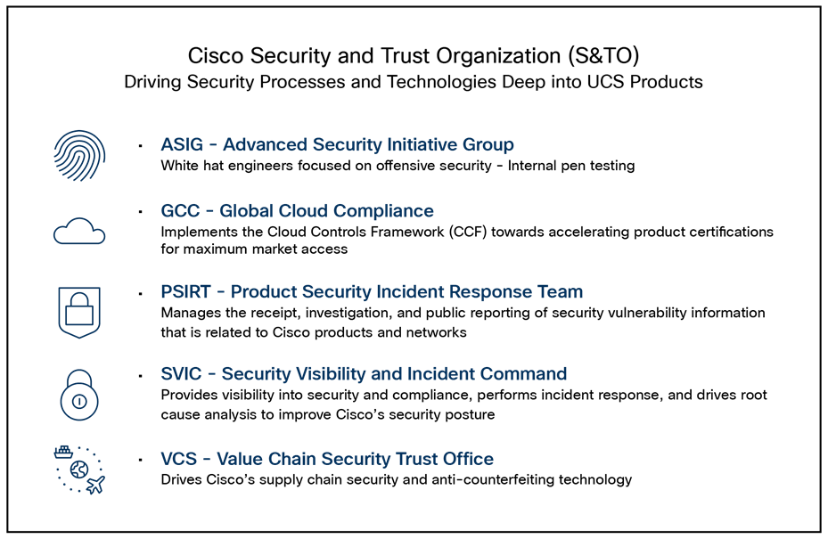
The groups within Cisco S&TO
Intersight’s ongoing commitment to security and compliance through annual external audits ensures that customer information is handled responsibly. In addition, Cisco’s Product Security Incident Response Team (PSIRT) manages the receipt, investigation, and public reporting of security vulnerabilities related to Cisco products and networks. The team works with Cisco customers, independent security researchers, consultants, industry organizations, and other vendors to identify possible security issues with Cisco products and networks.
A critical aspect of secure product development and deployment is ensuring that the components that go into the system are legitimate and uncompromised. To this end, Cisco takes exceptional measures to ensure supply chain integrity.
The Cisco Value Chain describes the development model used for all Cisco products, including Cisco HyperFlex®. Cisco is a leader in industry and international standards on counterfeit reduction and has been engaged in decades-long efforts to prevent and detect the distribution of counterfeit products. Cisco incorporates tools and processes to prevent counterfeiting—beginning with product development, through the manufacturing process, and in the marketplace.
In collaboration with Cisco’s Brand Protection, legal, and other teams, an end-user portal has been developed to aid customers in these efforts and can be accessed at: anticounterfeit.cisco.com.
Cisco’s Brand Protection Team has conducted numerous investigations into counterfeiting operations and worked with local law enforcement to disrupt those operations. The portal includes examples of the Brand Protection Team’s work over the years and the numerous resources that are available for Cisco customers and partners.
The Cisco Value Chain has the following characteristics:
● Comprehensive across all stages of a solution’s lifecycle
● Multilayer approach, with focused protection against:
◦ Source-code corruption
◦ Hardware counterfeit
◦ Misuse of intellectual property
This multilayered approach is shown in Figure 3.
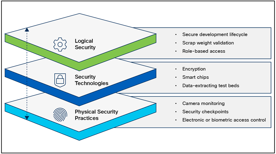
Layers of the Cisco Value Chain
Consortiums for secure vendors
Table 1. Secure vendor consortium memberships
| Name |
Component(s) |
Description |
Status |
| TAPA |
Supply chain |
The Transported Asset Protection Association’s (TAPA) Security Standards act as a worldwide benchmark for supply-chain security and resilience, providing guidance, processes, and tools that reduce loss exposure, protect assets, and the costs of cargo theft. |
Member |
| C-TPAT |
Supply chain |
Customs Trade Partnership Against Terrorism (CTPAT) Trade Compliance Program is a voluntary program that provides the opportunity for importers who have made a commitment of resources to assume responsibility for monitoring their own compliance in exchange for benefits. |
Member |
Advisories, vulnerabilities, and incident responses
Cisco’s Computer Emergency Response Team (CERT) advisories are transmitted when new vulnerabilities are identified. Cisco’s internal CERT team monitors and alerts product groups to potential issues that might affect their respective components. When these items are identified by CERT or are otherwise indicated by vendor partners (VMware, etc.), patches are either developed or acquired from the respective vendors. Cisco has heavily invested to protect customers by creating this team, which constantly monitors threats and builds a centralized solution to remediate these issues and vulnerabilities.
Additional vulnerability testing measures
Cisco also utilizes an internal tool for threat modeling called Threat-builder. This tool is used to explicitly map out application components and services and to identify potential attack surfaces and develop line items for direct evaluation. This information, along with industry tools, is used for vulnerability and exploit testing by Cisco’s ASIG (Advanced Security Initiatives Group). ASIG also uses fuzzing and manual testing as part of its suite of tools.
Running vulnerability scans against PVA/CVA
PVA and CVA have an abstracted shell (such as IOS®, HXCLI, etc.). You cannot run a credentialed root scan against this shell. The backing, embedded operating system is currently CentOS, but that will soon change to Alma. You will not be able to enter the development debug shell.
The Cisco Product Security Incident Response Team (PSIRT) is responsible for responding to Cisco product security incidents. The Cisco PSIRT is a dedicated, global team that manages the receipt, investigation, and public reporting of information about security vulnerabilities and issues related to Cisco products and services. Cisco defines a security vulnerability as a weakness in the computational logic (for example, code) found in software and hardware components that, when exploited, results in a negative impact to confidentiality, integrity, or availability. Cisco reserves the right to deviate from this definition based on specific circumstances. The Cisco PSIRT adheres to ISO/IEC 29147:2018, which is a set of guidelines for disclosure of potential vulnerabilities established by the International Organization for Standardization.
The Cisco PSIRT is on call and works 24 hours a day with Cisco customers, independent security researchers, consultants, industry organizations, and other vendors to identify possible security vulnerabilities and issues with Cisco products and networks.
All vulnerabilities disclosed in Cisco Security Advisories are assigned a Common Vulnerability and Exposures (CVE) identifier and a Common Vulnerability Scoring System (CVSS score) to aid in identification. Additionally, all vulnerabilities are classified based on a Security Impact Rating (SIR).
Cisco uses version 3.1 of CVSS as part of its standard process of evaluating reported potential vulnerabilities in Cisco products. The CVSS model uses three distinct measurements or scores that include base, temporal, and environmental calculations. Cisco provides an evaluation of the base vulnerability score and, in some instances, a temporal vulnerability score. End users are encouraged to compute the environmental score based on their network parameters.
In addition, Cisco uses the Security Impact Rating (SIR) to categorize vulnerability severity in a simpler manner. The SIR is based on the CVSS base score, adjusted by PSIRT to account for variables specific to Cisco, and is included in every Cisco Security Advisory.
Cisco PSIRT assigns a Common Vulnerabilities and Exposures Identifier (CVE ID) to any vulnerability that is found in Cisco products and that qualifies to receive this identifier. Usually, all vulnerabilities with medium, high, or severe SIRs — that is, a CVSS score of 4.0 or greater — will qualify for a CVE ID.
Cisco UCS has a unique architecture that integrates compute, data-network access, and storage-network access into a common set of components under a single pane of glass management interface. Cisco UCS fuses access-layer networking and servers. This high-performance, next-generation server system provides a data center with a high degree of workload agility and scalability. The hardware and software components support Cisco’s unified fabric, which runs multiple types of data-center traffic over a single converged network adapter.
A Cisco UCS compute system is available in many blade or rack-mount configurations. With Intersight, systems that come with Fabric Interconnects (FIs) are configured at build time to run with Intersight’s cloud-management services (Intersight Managed Mode, IMM). Systems without FIs will run in standalone mode and can be claimed by Intersight using a two-factor authentication mechanism that requires access to the system.
Cisco Intersight Virtual Appliance
Cisco Intersight Virtual Appliance delivers the management features of Intersight in an easy-to-deploy VMware OVA, Microsoft Hyper-V Server VM, and KVM hypervisor. Intersight Virtual Appliance provides the benefits of Cisco Intersight that offers an intelligent level of management to enable customers to analyze, simplify, and automate their environments in more advanced ways than the previous generations of tools, while allowing more flexibility with additional data locality, security, and compliance requirements.
You can deploy Intersight Virtual Appliance in one of the following modes:
● Intersight Connected Virtual Appliance
● Intersight Private Virtual Appliance
Intersight Connected Virtual Appliance delivers the management features of Intersight while allowing you to control what system details leave your premises. Intersight Connected Virtual Appliance deployments require a connection back to Cisco and Intersight services for automatic updates and access to services for full functionality.
Intersight Private Virtual Appliance delivers the management features of Intersight and allows you to ensure that no system details leave your premises. Intersight Private Virtual Appliance deployments are intended for an environment where you operate data centers in a disconnected (air-gapped) mode.
For an overview of Intersight Assist, see About Cisco Intersight Assist.
You can deploy Intersight Virtual Appliance as a single-node virtual machine in your existing environment.
You can also deploy Intersight Virtual Appliance on VMware vSphere as a multi-node cluster, which allows for high availability. Once you have completed the initial setup of the single-node appliance, you can add additional nodes. After you successfully add two additional nodes, you can create a multi-node cluster in Intersight Virtual Appliance.
Multi-node Intersight Virtual Appliance
The Intersight Virtual Appliance is capable of multi-node deployment for fault tolerance. This provides customers with a highly available and resilient on-premises deployment option to manage their data-center infrastructure.
● Appliance resiliency – Protection against disruptions, thus providing zero downtime for Intersight services
● Flexible configuration – Virtual nodes available within or across data centers if meeting latency and bandwidth requirements
● Migration path from a single-node deployment – Expandable from existing deployments to leverage these new capabilities
For more information:
● Configuring a Multi-Node Cluster for Intersight Virtual Appliance
● Migration Path for Expanding Existing Single-Node Deployment to Multi-Node Cluster Configuration
Federal compliance and audit-based certifications are a critical component of a standardized and predictable security posture. They are critical in most federal deployments, especially those dealing with financial and defense arenas. The Cisco Global Certification Team (GCT) works to complete various certifications.
SOC 2 Type 2
System and Organization Controls (SOC) (also sometimes referred to as service organizations controls), as defined by the American Institute of Certified Public Accountants (AICPA) is the name of a suite of reports produced during an audit. SOC is intended for use by service organizations (organizations that provide information systems as a service to other organizations) to issue validated reports on internal controls over those information systems to the users of those services.
SOC compliance and audits are intended for organizations that provide services to other organizations. For example, a company that offers cloud-hosting services may need SOC compliance. For Cisco and its customers, this is relevant for the Cisco Intersight SaaS cloud service.
There are two levels of SOC reports that are also specified by Statement on Standards for Attestation Engagements (SSAE) 18:
● Type 1, which describes a service organization’s systems and whether the design of specified controls meets the relevant trust principles
● Type 2, which also addresses the operational effectiveness of the specified controls over a period of time (usually 9 to 12 months)
There are three types of SOC reports:
● SOC 1 – Internal Control over Financial Reporting (ICFR)
● SOC 2 – Trust Services Criteria
● SOC 3 – Trust Services Criteria for General Use Report
SOC 2 Type 2 certified: meets controls for confidentiality, security, and availability, among others.
SOC 2 reports focus on controls addressed by five semi-overlapping categories called Trust Service Criteria:
1. Security
a. Firewalls
b. Intrusion detection
c. Multifactor authentication
2. Availability
a. Performance monitoring
b. Disaster recovery
c. Incident handling
3. Confidentiality
a. Encryption
b. Access controls
c. Firewalls
4. Processing integrity
a. Quality assurance
b. Process monitoring
c. Adherence to principle
5. Privacy
a. Access control
b. Multifactor authentication
c. Encryption
The SOC 2 Audit provides the organization’s detailed internal controls report made in compliance with the five trust service criteria. It shows how well the organization safeguards customer data and assures them that the organization provides services in a secure and reliable way.
SOC 3
SOC 3 for Service Organizations: Trust Services Criteria for General Use Report is a short, publicly facing summary of the SOC 2 Type 2 attestation report for users who need assurances about a service organization’s controls but do not need a full SOC 2 report or are not eligible under SOC 2 to receive one. Because SOC 3 reports are general-use reports, they can be freely distributed.
A SOC 3 report contains a written assertion by service-organization management regarding control effectiveness to achieve commitments based on the applicable trust services criteria, and the service auditor’s opinion on whether management’s assertion is stated fairly.
Cisco Intersight SOC 3 https://trustportal.cisco.com/c/r/ctp/trust-portal.html?search_keyword=intersight#/1632370623703433.
FIPS
The Federal Information Processing Standard (FIPS) Publication 140-2 is a U.S. government computer-security standard used to approve cryptographic modules.
Cisco UCS is compliant with FIPS140-2 level 1 through direct implementation of the FIPS-compliant Cisco SSL crypto module. The module, once implemented, is vetted by a third party that is federally certified to ascertain compliance status.
● Utilizes Cisco SSL module
◦ Already FIPS compliant
◦ SSH-approved cipher list
◦ SSL/TLS implementation
◦ Eliminates weak or compromised components
● Regularly updated
● Lab validates that the module is incorporated correctly
◦ Build logs
◦ Source-access-identifying calls to the module
◦ All admin access points to the cluster are covered here
● SSH for CLI
● HTTPS for UI
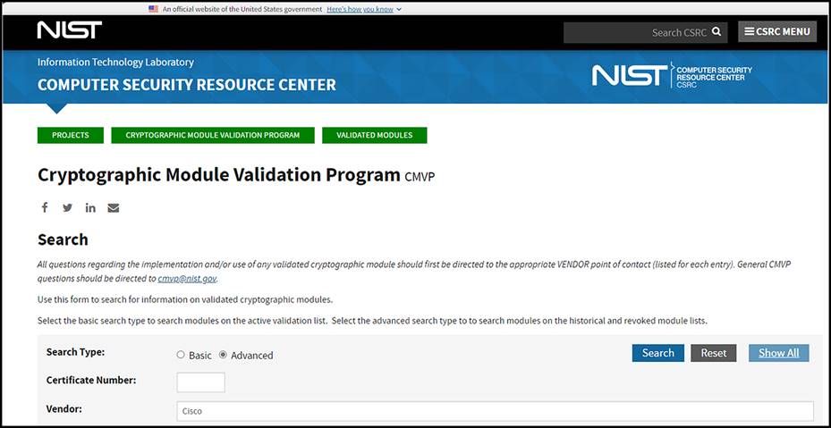
A comprehensive list of Cisco FIPS-compliant products is given below, along with the corresponding reference with NIST:
● Cisco FIPS-certified products: https://www.cisco.com/c/en/us/solutions/industries/government/global-government-certifications/fips-140.html
● Cryptographic Module Validation Program (CMVP) vendor list: Cryptographic Module Validation Program | CSRC (nist.gov)
FIPS vendor listings
Note: FIPS 140-2 level 2 on PVA/CVA is only applicable to single-node appliance.
CNSA (Commercial National Security Algorithm)
This is a schema that is detailed in RFC 9151: RFC 9151: Commercial National Security Algorithm (CNSA) Suite Profile for TLS and DTLS 1.2 and 1.3 (rfc-editor.org)
The Commercial National Security Algorithm (CNSA) describes which algorithms should be in use and what their profiles should look like. It is intended to give guidance for secure and interoperable communications, including guidelines for certificates, for national security reasons.
Cisco supports both Elliptic Cryptographic Certificates (ECC) and RSA certificates, so these requirements are met:
● Elliptic Curve Digital Signature Algorithm (ECDSA) and Elliptic Curve Diffie-Hellman (ECDH) key pairs are on the curve P-384. FIPS 186-4, Appendix B.4, provides useful guidance for elliptic curve key pair generation that should be followed by systems that conform to the RFC.
● RSA key pairs (public or private) are identified by the modulus size expressed in bits; RSA-3072 and RSA-4096 are computed using moduli of 3072 bits and 4096 bits, respectively. Cisco’s FIPS certification through Cisco SSL implements federally approved crypto modules to satisfy the complexity requirements as well.
CNSA compliance is just a matter of making sure to implement a cryptographic ecosystem according to the CNSA requirements since Cisco UCS supports all the documented methods.
FIPS 140-3
FIPS 140-3 is the successor to FIPS 140-2. FIPS 140-3 became effective on September 22, 2019. FIPS 140-3 testing began on September 22, 2020, and a small number of validation certificates have been issued. FIPS 140-2 testing was available until September 21, 2021, creating an overlapping transition period of one year. FIPS 140-2 test reports that remain in the CMVP queue will still be granted validations after that date, but all FIPS 140-2 validations will be moved to the Historical List on September 21, 2026, regardless of their actual final validation date.
Beginning with PVA/CVA version 1.1.4-0, FIPS 140-3 compliance has been achieved. The letter is available here.
Versions of Cisco software using CiscoSSL version 8.3 or later are certified for FIPS 140-3 level 1 encryption. Note that CisoSSH uses the cryptographic engine from CiscoSSL so that it is automatically covered. This includes the latest UCSM and CIMC software that manages the Device Connector for communication to Intersight SaaS as well as Intersight appliances such as the PVA (Private Virtual Appliance) and the CVA (Connected Virtual Appliance). The certification letter can be found here (Cryptographic Module Validation Program | CSRC).
Other certifications and procedural guidelines
ISO/IEC 27001 is not a certification for specific pieces of hardware as much as it is a dozen or so “best practices” in the form of checklists and guidelines for how organizations manage their security controls internally. It observes such things as building access, password management, badging into a copier to make copies, etc. Training on a frequent basis is a part of the standard.
Cisco is ISO/IEC 27001-certified. This is a link to our ISO/IEC 27001 certificate: Cisco Secure Cloud Analytics (StealthWatch®) ISO/IEC 27001:2013, 27017:2015, 27018:2019.
ISO/IEC 27001:2013: the Cisco Intersight platform has completed its ISO/IEC 27001:2013 First Surveillance Audit from the external certification body/auditor Coalfire, and the certificate issued has been uploaded to Trust Portal site. The First Surveillance Audit included a review of the establishment and overall operating effectiveness of control areas that form Cisco Intersight’ s information security management system.
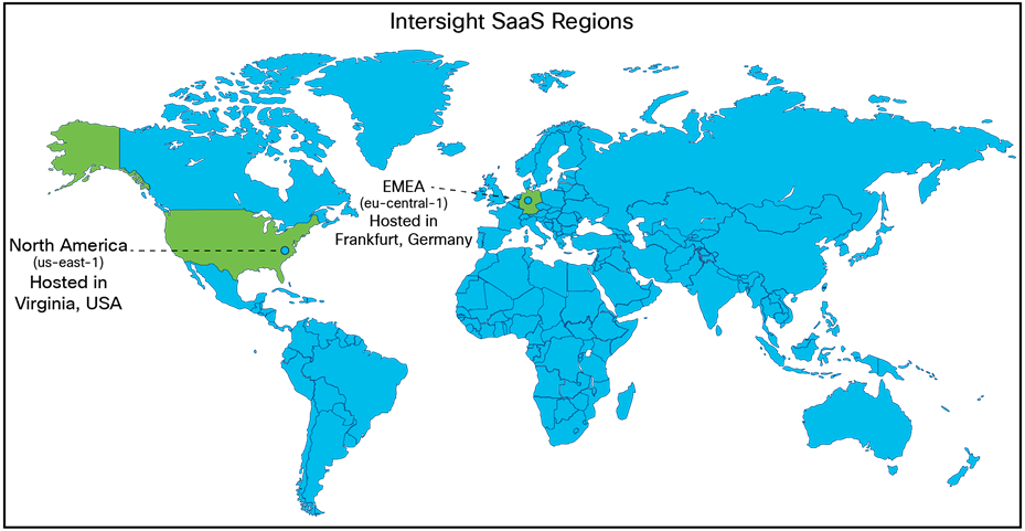
Cisco Intersight supports two regions: the existing North America region (us-east-1) and the Europe, Middle East, and Africa (EMEA) region (eu-central–1).
Benefits include:
● Compliance: multi-region support helps meet local regulatory requirements such as control, confidentiality of personal and sensitive data, availability, and service resilience.
● Improved performance and latency: deployments can use an Intersight instance closer to the geographic location of users and devices.
● Seamless connection and configuration: no new workflows are required. All regions include the same familiar Intersight configuration and management experience. Connection and configuration changes are also the same in all regions.
● Data sovereignty with the same user experience: the Intersight EMEA user experience is the same in all regions. Users are automatically redirected to their account’s region to maintain data sovereignty requirements.
Intersight global regions
The various regions offer global feature parity. All regional customers enjoy all new features at the same time. Creating new Intersight accounts is also as simple as using a drop-down menu, as shown in Figure 6.
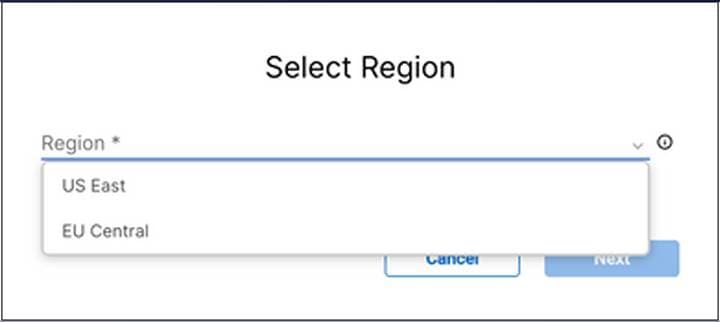
Region selection on account creation
The selected region determines which Intersight SaaS regional instance will be used to store customers’ data to help comply with local laws and data residency regulations while achieving low latency. Users can seamlessly switch between accounts in different regions.
The Intersight claiming process is unified for all regions. When a target is claimed, data is stored in the region of the account that claimed the target, and all interactions with Intersight are performed in the local region. In the example multi-region illustration below, targets in Spain, United Kingdom, and India are managed by the EMEA instance while targets in Australia, Africa, and South America are managed by the North American instance.
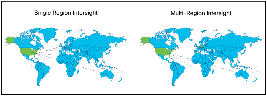
Multi-region Intersight account locations
If you are using Intersight SaaS or the CVA and either created your account before the EMEA instance was available or selected the wrong region during account creation, there is no back-end migration of data to the EMEA instance. Normally a CVA is claimed to an Intersight account just as a regular endpoint is claimed in a SaaS deployment. This Intersight account can be created in the U.S. or Europe. If a CVA or endpoint is claimed to an Intersight account in the U.S., then it stays there. If the data is required to be kept in the EMEA instance, then an Intersight account should be created in the EMEA hub, and the CVA and/or endpoints need to be unclaimed from the old account in the U.S. and reclaimed to the new account in EMEA.
Intersight point-of-presence replication and attack hardening
Enterprise security services that are internet exposed must be able to be deployed such that they are resilient to volumetric Distributed Denial of Service (DDOS) and common web-based attacks. These are handled by Amazon Web Services (AWS) security services that host Cisco Intersight SaaS. Similarly, AWS manages the multi-PoP (point of presence) and active/failover configurations as defined in the AWS Recovery Point Objective (RPO) and Recovery Time Objective (RTO) contracts.
Intersight privacy and data retention
Intersight collects a subset of the information in the Intersight privacy data sheet.
For details, see Cisco Cloud Services delivered by the Intersight Platform, including Nexus® Cloud Privacy Data Sheet.
Usage notes for the EMEA (eu-central–1) region:
● Inventory data for unclaimed devices is temporarily stored in the U.S. region until the device is claimed by an EMEA account. After the device is claimed, any previously collected data is purged from the generic U.S. Intersight account to which all unclaimed devices belong. The data is retained in the Intersight backup as specified in the Cisco Cloud Services delivered by the Intersight Platform Data Sheet.
● Cisco Technical Assistance Center (Cisco TAC) support, as a global service, may need to move customer tech-support data to a different region for troubleshooting and analysis. Deployments can use an Intersight instance closer to the geographic location of users and devices.
● The Intersight default setting for tech support is to allow collection of incident information. To turn this off, see Disabling Tech Support Bundle Collection. Only an account administrator can modify the setting.
● The Proactive RMA system automatically generates a Service Request (SR) and a Return Material Authorization (RMA) when products experience certain failures. To turn off this service, see Opting out of Proactive RMAs.
Data collected and encrypted at rest
● The Intersight platform has complete visibility into and control over managed systems, the same as local API access. Data collected from device connectors on managed systems may include the following:
◦ Inventory and configuration data for fabric interconnects and all servers and nodes, including storage controllers, network adapters, I/O modules, and CPUs
◦ Server operational data (such as faults) that can be used by the Intersight platform to provide automated recommendations
◦ Technical support files that can be created when requested by Cisco TAC
Note that device connectors do not collect sensitive data that may be stored in the connected systems, such as passwords. If you use the Cisco Intersight Connected Virtual Appliance, you have control over whether the above data is passed on to the cloud-based portal. If you opt out of additional data collection, the above information is kept locally. The Intersight help pages have more information on data collected by the on-premises Cisco Intersight Virtual Appliance.
For all data collected, the following additional security practices are implemented:
● Customer data is kept separate from other customer data through virtual data segregation. Data requests by Cisco Intersight services return data specific to the customer account only, and per-customer encryption keys are used for access.
● Long-term persistent data is encrypted at rest. Block storage or similar volume encryption is enabled for all data and tenant files.
● Third-party access to data is not permitted.
There is no user data that is stored in any Intersight instance; only meta-data is collected. If you have a support case open with Cisco TAC, only the TAC engineer that is assigned to the Support Request (SR) created by the end user can generate tech-support logs.
Cisco TAC does not have access to login data. TAC engineers can generate tech-support bundles, but policies, profiles, pools, etc., are not exposed in the case viewer for TAC. The TAC team uses the “Technical Assistance User” role, which is defined as a “Limited number of approved Cisco employees with read-only access to the Intersight web portal UI across all Intersight accounts, and the ability to trigger serviceability functions such as tech support bundle collection and downloading tech support data.”
Expected by Q3CY24, instead of enabling the general Technical Assistance User role for TAC, a new “TAC Support-Services role” will provide read-only access to specific TAC engineers based on the mapping of an SR and authorization to the TAC engineer.
Engineers will be able to operate with the “support-services” role in the customer’s account, giving the customer auditability of which TAC engineers were able to see their data.
Even after this is implemented, TAC will never have access to passwords to log into devices.
Tech-support bundles are retained for two years. The meta data from CVA is retained while the Intersight account is active.
Backing up of a Cisco Intersight Virtual Appliance regularly is essential. Without regular backups, there is no automatic way to reconstruct the configuration settings and recreate the profiles and policies. You can perform a regular backup once a day using a scheduled backup or create backup to guard against a data-loss or -corruption event. Cisco Intersight Virtual Appliance enables you to take a full-state backup of the data in the appliance and store it in a remote server. If there is a total site failure or another disaster recovery scenario, the restore capability enables you to do a full-state-system restore from the backed-up system data.
The following options are available to back up data:
● Create backup — creates on demand a full-state backup of the data in Cisco Intersight Virtual Appliance and saves the backed-up data on a remote server
● Schedule backup — performs a full-state periodic backup of the data in the appliance based on a schedule and saves the backed-up data on a remote server
Intersight service level objectives and agreements
Intersight Service Level Objectives (SLOs) are documented in the Cisco Trust Portal here:
https://trustportal.cisco.com/c/r/ctp/trust-portal.html#/19645092958710743
● The SLO details what you can expect from Cisco in terms of handling cloud-based service outages and maintenance requirements. It explains what qualifies for these labels and what you can expect from Cisco in these events.
● Note that the SLO from Cisco is distinct from the SLA and SLO from AWS, which provides the infrastructure for the cloud services, by contract, with Cisco. These policies are described below and are what Cisco, and by extension, the customer, can expect from the infrastructure as a whole.
● The following two links show what AWS delivers for cloud providers like Cisco:
◦ AWS Service Level Agreements - https://aws.amazon.com/legal/service-level-agreements/
◦ Reliability Pillar - AWS Well-Architected Framework - Reliability Pillar - https://docs.aws.amazon.com/wellarchitected/latest/reliability-pillar/welcome.html
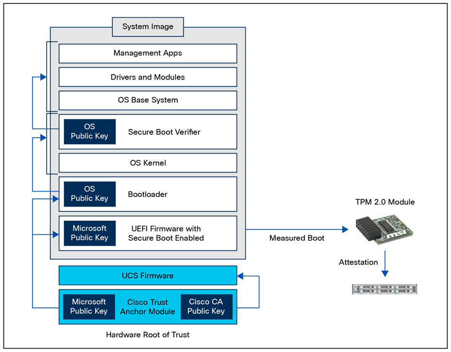
A secure system boot relies on a set of trusted Cisco technologies. Here are the fundamental concepts of Cisco trustworthy technologies:
A chain of trust exists when the integrity of each element of code in a system is validated before that piece of code is allowed to run. A chain of trust starts with a root-of-trust element. The root of trust validates the next element in the chain (usually firmware) before it is allowed to start, and so on. Using signing and trusted elements, a chain of trust can be created that boots the system securely and validates the integrity of Cisco software.
Hardware root of trust – Trust Anchor Module (TAM) and Trusted Platform Module 2.0 (TPM)
A trusted element in a system’s software is a piece of code that is known to be authentic. A trusted element must either be immutable (stored in such a way as to prevent modification) or authenticated through validation mechanisms. Cisco anchors the root of trust, which initiates the boot process, in tamper-resistant hardware. The hardware-anchored root of trust protects the first code running on a system from compromise and becomes the root of trust for the system.
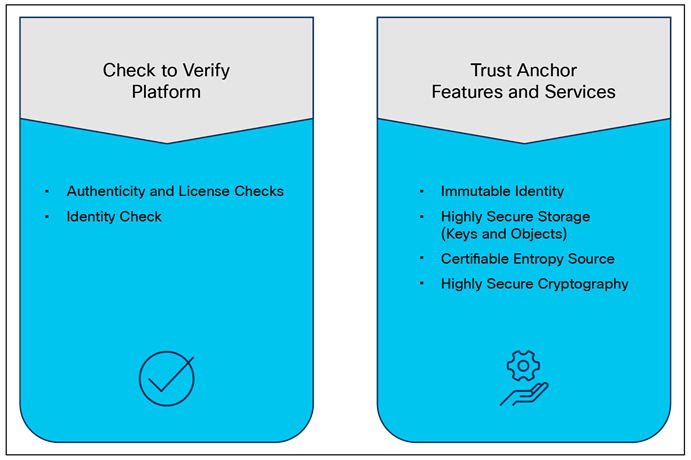
The Trust Anchor module (TAM) is a proprietary, tamper-resistant chip found in many Cisco products and features nonvolatile secure storage, a Secure Unique Device Identifier (SUDI), and crypto services, including Random Number Generation (RNG), secure storage, key management, and crypto services for the running OS and applications.
The hardware root of trust is a Cisco ACT2 Trust Anchor Module (TAM). This module has the following characteristics:
● Immutable Identity with IEEE 802.1AR (Secure UDI- X.509 cert)
● Anti-theft and anti-counterfeiting
● Built-In cryptographic functions
● Secure storage for certificates and objects
● Certifiable NIST SP800-92 random number generation
Once a system is securely booted, it is often important to get external verification that this is indeed the case. This is done through attestation. “Attestation” is evidence of a result, that is, “The host was booted with secure boot enabled and signed code.” This is accomplished through the Trusted Platform Module (TPM).
The Secure Unique Device Identifier, or SUDI, is an X.509v3 certificate that maintains the product identifier and serial number. The identity is implemented at manufacturing and is chained to a publicly identifiable root-certificate authority. The SUDI can be used as an unchangeable identity for configuration, security, auditing, and management.
The SUDI credential in the Trust Anchor module can be either RSA- or Elliptic Curve Digital Signature Algorithm (ECDSA)–based. The SUDI certificate, the associated key pair, and its entire certificate chain are stored in the tamper-resistant Trust Anchor module chip. Furthermore, the key pair is cryptographically bound to a specific Trust Anchor chip, and the private key is never exported. This feature makes cloning or spoofing the identity information virtually impossible.
The SUDI can be used for asymmetric key operations such as encryption, decryption, signing, and verifying that allow passage of the data to be operated upon. This capability makes remote authentication of a device possible. It enables accurate, consistent, and electronic identification of Cisco products for asset management, provisioning, version visibility, service entitlement, quality feedback, and inventory management.
TAM functions
Currently the secure boot process, when enabled, is in effect during boot, including of both the system firmware and the installed operating system. The end-to-end security model that this enables, when combined with the secure UI and CLI, encompasses the hardware Trust Anchor module (TAM) to secure the system boot and to secure the OS boot with externally verifiable attestation using the Trusted Platform Module (TPM).
This implementation covers the following:
● Secure boot, secured by public keys stored in the write-protected hardware root of trust.
● Ensuring that only a trusted OS image, including drivers, is booted by verifying signatures.
● Attestation of secure boot through TPM 2.0.
The detailed process flow for secure boot of the system and OS with attestation capability is shown below. Note that the certificate-based hardware root of trust validates the UCS firmware, which ensures a clean BIOS set for key validation of the hypervisor bootloader, and so on. This guarantees that the hardware and hypervisor in the HyperFlex system have not been tampered with. External validation of this can be made through attestation using the TPM 2.0 module in UCS.
The Infineon OPTIGA TPM SLB 9672 supports comprehensive self-tests as required by the TCG TPM 2.0 specification, using commands such as TPM2_SelfTest to verify integrity. Self-tests that are run on power-up or on-demand – with results retrieved via TPM2_GetTestResult and inField Upgrade Mode tests – are invoked to check the device status.
TPM 2.0 requires Cisco UCS Manager versions 2.2(7) or 3.1(1) or later and Cisco IMC versions 2.0(10) or later for support. The TPM modules used conform to TPM 2.0 as defined by the Trusted Computing Group (TCG), and specifically the Infineon TPM SLB 9672 module is used in these platforms. TPM installation is supported after factory but is secured by a one-way screw and cannot be replaced or moved to another server. If a server with TPM is returned, the replacement must be ordered with a new TPM module.
Image signing
Image signing is a two-step process for creating a unique digital signature for a given block of code. First, a hashing algorithm, similar to a checksum, is used to compute a hash value of the block of code. The hash is then encrypted with a Cisco private key, resulting in a digital signature that is attached to and delivered with the image. Signed images may be checked at runtime to verify that the software has not been modified.
Secure boot
Cisco Secure Boot helps to ensure that the code that executes on Cisco hardware platforms is authentic and unmodified. Cisco hardware-anchored secure boot protects the microloader (the first piece of code that boots) in tamper-resistant hardware, establishing a root of trust that helps prevent Cisco network devices from executing tainted network software. Subsequent boot of the installed operating system is verified and attested with the Trusted Platform Module (TPM).
Cisco Secure Boot helps ensure that the code that executes on Cisco hardware platforms is genuine and untampered. A typical UEFI-based boot process starts at the UEFI firmware and works up to the boot loader and the operating system. A tampered UEFI firmware can result in the entire boot process being compromised.
Using a hardware-anchored root of trust, digitally signed software images, and a unique device identity, Cisco hardware-anchored secure boot establishes a chain of trust that boots the system securely and validates the integrity of the software. The root of trust (a.k.a. the microloader), which is protected by tamper-resistant hardware, first performs a self-check, and then verifies the UEFI firmware, and thus kicks off the chain of trust leading to integrity verification of the entire operating system.
Secure Boot process
Messages related to secure boot will appear in syslog entries. Syslog will contain entries from the event log and the audit log. As such, these entries fall into one of 3 categories: faults, events (information), and audit entries (system changes). Each syslog message identifies the Cisco UCS Manager process that generated the message and provides a brief description of the operation or error that occurred. This means that secure boot messages will be whether secure boot (at the time of action - audit record) is enabled, disabled, or (faults) if there were any issues during the boot process due to signature verification failures when secure boot is enabled.
In general, on secure boot failure the image should roll back or boot the golden image. For BIOS on x86 servers, there should be logging of secure boot failures and UEFI secure boot violations if UEFI secure boot is enabled. For BIOS there isn’t an automatic boot of the old image.
Specific events:
● Secure Boot Enabled/Disabled: Logs when secure boot is enabled or disabled on a server.
● Invalid Bootloader: Messages indicating attempts to boot with an unsigned or invalid bootloader.
● Policy Violation: Logs when a secure boot policy is violated (e.g., booting with a non-approved boot image).
● Verification Errors: Messages detailing any errors encountered during the secure boot verification process.
● “Secure Boot Enabled”: Indicates that the CIMC secure boot feature is currently active and only signed firmware images are allowed to boot.
● “Secure Boot Disabled”: Means the CIMC secure boot feature is not currently in use.
● “Secure Boot Verification Failure”: A critical message signifying that the system attempted to boot a firmware image that did not pass signature verification, potentially due to an invalid or unsigned firmware.
Accessing syslog messages:
● CIMC: Under Chassis-->Faults and Logs you can view system event log and the IMC log (audit). Under Logging Controls, you can configure the syslog server.
● UCS Manager CLI: Use commands like show logging to view syslog messages on the UCS Manager.
● UCS Manager UI: Navigate to the “Admin” tab in the UCS Manager GUI, then expand “Faults, Events, and Audit Log” and select “Syslog”.
● IMM: In Intersight, select the server of interest, and then in the actions menu select system, then download system event log. The audit records for all items in the organization, including the server of interest, are available under System-->Audit logs in the left navigation menu.
● External Syslog Server: Each management mode has a syslog configuration setting. In CIMC it is under chassis-->faults and logs-->logging controls. In UCSM and IMM configure a syslog policy for the individual servers.
● In all cases, a Tech Support generated for the system will contain all logs.
References:
● Monitoring Cisco UCS Manager using Syslog
● Cisco UCS Manager Administration Management Guide 4.3
Secure boot vendor key updates
When a vendor, such as Microsoft, updates or otherwise changes their secure signatures, these keys need to be updated on the UCS system to maintain secure boot operations. These updated certificates are embedded in the signed and secured Cisco UCS Firmware. When the UCS system firmware is updated, these new keys are added, and secure boot continues to function. This is an ongoing process from various vendors and from Cisco and happens automatically.
See the following Tech Note that describes the update to the Microsoft Secure Boot Certificate that took place in 2026: https://www.cisco.com/c/en/us/support/docs/servers-unified-computing/unified-computing-system/225712-mitigate-microsoft-secure-boot.html
Runtime Defenses (RTDs) target injection attacks of malicious code into running software. Cisco runtime defenses include Address Space Layout Randomization (ASLR), Built-in Object Size Checking (BOSC), and X-Space. Runtime defenses are complementary.
● They make it harder or impossible for attackers to exploit vulnerabilities in running software.
● Since runtime defenses are complementary, you can implement them individually or deploy several runtime defenses together.
Cisco UCS supports both Intel® and AMD processors. The latest generations of these CPUs and their accompanying chipsets have extensions and programmatic capabilities around memory encryption and secure code execution and isolation.
Intel Boot Guard (4th gen CPU and greater) is a security technology designed to enhance the integrity of the boot process and protect against unauthorized firmware and bootloader modifications on systems using Intel processors. It is part of Intel’s broader security initiatives to safeguard the boot process from potential threats and ensure the system starts up securely.
AMD Platform Secure Boot (PSB)
AMD Platform Secure Boot (PSB) is a security feature designed to enhance the security of AMD processors and platforms by focusing on the boot process. PSB is part of AMD’s security initiatives to protect against unauthorized code execution during the system boot-up process.
Post Quantum Cryptography and UCS
See “Appendix C – PQC definitions” for definitions of various PQC terminology.
NSA defines the cryptography requirements for National Security Systems (NSS) used in Commercial National Security Algorithm (CNSA) Suite documents. CNSA is the NSA’s mandated suite of conventional algorithms, and CNSA 2.0 is the post-quantum suite. A list of the CNSA 1.0 and CNSA 2.0 algorithms is shown below.
CNSA requirements are enforced by inclusion in Common Criteria (CC) and Commercial Solution for Classified (CSfC) certifications. New versions of Common Criteria (CC) Protection Profiles (PPs) have been created that include the use of CNSA 1.0 or CNSA 2.0 requirements. CSfC currently requires CNSA 1.0. CSfC updates allowing CNSA 2.0 are now available.
In 2026, network devices are required to comply with either CNSA 1.0 or 2.0. The transition is dependent on use cases, such as FW/SW signatures and verification, when it is not feasible to support both CNSA 1.0 and 2.0. Many use cases, such as transport protocols, allow support for both CNSA 1.0 and 2.0.
CNSA 2.0 instructs government buyers to prefer compliance in 2026, and it requires compliance by 2030. CNSA 2.0-required compliance will likely be accelerated to 2027 for CSfC.
Table 2. PQC algorithms
| Function/use case |
Algorithms |
|
| CNSA 1.0 |
CNSA 2.0 |
|
| General system-wide, secret-based encryption and decryption |
AES-256 |
|
| General system-wide secure key exchange protocol |
ECDH-384 |
ML-KEM-1024 (CRYSTAL-Kyber 1024) |
| DH-3072 |
||
| RSA-3072 |
||
| SUDI and AIK certificates’ signature signing and verification |
ECC P-384 |
ML-DSA-87 (CRYSTALS-Dilithium) |
| RSA-3072 |
||
| General system-wide hashing usage |
SHA |
SHA |
| Use SHA-384 for all classification levels |
Use SHA-384 or SHA-512 for all classification levels |
|
| Image signing |
RSA-3072 |
LMS* |
|
|
XMSS |
|
|
|
||
| ECC P-384 |
||
| ML-DSA-87 (CRYSTALS-Dilithium) |
||
For general encryption, used when we access secure websites, NIST has selected the CRYSTALS-Kyber algorithm. Among its advantages are comparatively small encryption keys that two parties can exchange easily, as well as its speed of operation.
For digital signatures, used when we need to verify identities during a digital transaction or to sign a document remotely, NIST has selected the three algorithms CRYSTALS-Dilithium, FALCON, and SPHINCS+ (read as “Sphincs plus”). Reviewers noted the high efficiency of the first two, and NIST recommends CRYSTALS-Dilithium as the primary algorithm, with FALCON for applications that need smaller signatures than Dilithium can provide. The third, SPHINCS+, is somewhat larger and slower than the other two, but it is valuable as a backup for one chief reason: it is based on a different math approach than all three of NIST’s other selections.
The top priority for Software (SW) is PQC for transport protocols to protect against “Harvest Now, Decrypt Later” (HNDL) attacks. In these scenarios, users are at risk of having their information exposed in the future. This is mitigated through the use of PQC algorithms. CiscoSSL and CiscoSSH, the crypto modules used in UCSM and CIMC, are currently in early testing before general availability.
The second priority is image signing and verification. While initially used to support quantum-safe hardware requirements, support will travel up the software stack as verification capabilities become available with various vendors (for example, Microsoft) providing PQC keys for use.
The third priority is identities and certificates. Viable support depends on numerous external entities, such as standards (NIST, IETF, etc.), PKI vendors, and the Certification Authority Browser (CAB) Forum. The migration to PQC certificates will occur once all the industry vendor pieces are in place.
The top priorities for New Product Introduction (NPI) Hardware (HW) are PQC algorithms for software/firmware verification and device identities. CNSA 2.0 requests vendors to upgrade their existing products to versions that have these PQC capabilities. Users have asked Cisco about this upgrade capability. However, many Cisco devices support LDWM for secure-boot bootloader validation, a quantum-safe algorithm; therefore, it is not recommended to update a device’s identity for security concerns. In-field upgrades of Cisco hardware to incorporate PQC capabilities are not warranted in most cases.
There are three methods of running Intersight Managed Mode (IMM). These depend on the type of deployment the end user needs. For example, if there is a requirement for an air-gapped environment, but IMM is needed, an on-premises version of Intersight can be used. Here are the types of Intersight deployments:
● Cloud-based Cisco UCS management (Intersight SaaS)
◦ This cloud-native approach provides a centralized, web-based interface accessible from anywhere. It simplifies IT management by eliminating the need for on-premises hardware and software, making it an ideal choice for organizations seeking agility, scalability, and easy access to the latest features.
● Connected virtual appliance (Intersight CVA)
◦ For businesses that prefer an on-premises solution while still benefiting from cloud connectivity, the connected virtual appliance is the answer. It offers the flexibility to run the Intersight virtual appliance within the data center while maintaining seamless connections to the Intersight cloud for updates and technical support.
● Private virtual appliance (Intersight PVA)
◦ If security and isolation are important factors, the private virtual appliance delivers an on-premises, air-gapped option. It operates in complete isolation from the Intersight cloud and the internet, ensuring that the infrastructure remains secure while still taking advantage of Intersight’s management capabilities.
Each of these deployments offers the following benefits:
● Unified management
◦ Intersight consolidates the management of compute, network, storage, and hyperconverged infrastructure, simplifying the management of complex IT environments.
● Automation and orchestration
◦ Intersight automates routine processes, which, in turn, reduces errors and accelerates deployments.
● Optimized operations
◦ With proactive monitoring and intelligent analytics, Intersight helps identify and resolve issues before they impact an organization’s business, ensuring maximum uptime.
● Security and compliance (including Hardware Compatibility List [HCL] features)
◦ Stay ahead of security threats with real-time security alerts and compliance checks, keeping infrastructure protected and compliant with industry standards. Cisco Intersight also offers comprehensive Hardware Compatibility List (HCL) features, ensuring that an organization’s hardware is not only compatible but also fully supported for seamless operations. The HCL features provide detailed insights into hardware compatibility, allowing informed decision making and optimal infrastructure for peak performance.
● Intersight Monitoring Services (IMS)
◦ IMS provides historical and real-time visibility of resource consumption and inventory health, policies for notifications based on thresholds and anomaly detection, and actions and recommendations for automated infrastructure changes in response to events. IMS helps reduce operational costs, prevent SLA violations, and increase system reliability and availability.
Data encryption and connection security
Secure and encrypted communication channels include only up-to-date and approved protocols and are used when migrating servers, services, applications, or data to cloud environments. Intersight is ISO 27001 and SOC 2 Type 2 certified, the highest level of certifications for cloud-based services. SOC 2 focuses controls as they relate to security, availability, processing integrity, confidentiality, and privacy of a system. To maintain SOC 2 Type 2 certification, companies must undergo periodic audits that prove their systems and control activities are effective over time.
Certified FIPS compliance for all communications:
● Intersight Connected Virtual Appliance
● Intersight Private Virtual Appliance
● Intersight Assist
The Transport Layer Security (TLS) session reuse timeout default is five minutes, but not the session close. The device connector establishes a persistent web socket, so the connection to Intersight is permanent.
Your Intersight web UI session is not permanent. If your session is idle for more than 30 minutes, your session will be removed.
For a successful target connection to Intersight, ensure that the following connectivity requirements are met:
● Establish a network connection to the Intersight platform from the Intersight device connector.
● Ensure that Intersight Management is enabled in Device Connector (it is enabled by default). You can find Intersight Management in Admin > Device Connector > Intersight Management in Cisco UCS Manager/Cisco UCS Director/Cisco IMC, and Settings > Device Connector in the Cisco HyperFlex UI.
● Check if a firewall is introduced between the managed target and Intersight, or if the rules for an existing firewall have changed, thus affecting connectivity. If the rules are changed, ensure that the changed rules permit traffic through the firewall.
● Ensure that all applicable physical and virtual IPs are allowed through the firewall.
● If you use an HTTP proxy to route traffic out of your premises, and if you have made changes to the HTTP proxy server’s configuration, ensure that you change the device connector’s configuration accordingly. This is required because Intersight does not automatically detect HTTP proxy servers.
● A valid CA-signed certificate is presented by the Intersight portal.
● Configure DNS and resolve the DNS name. The device connector must be able to send DNS requests to a DNS server and resolve DNS records. The device connector must be able to resolve URLs required by device connectors to an IP address.
● Caution: Hosting the DNS used for Intersight DNS resolution in the same environment as what is being managed is not recommended.
● Configure NTP and validate that the device time is properly synchronized with a time server.
● Note: When the device time is not properly synchronized, the device connector may be unable to establish a secure connection to Intersight, and the TLS certificate may be considered invalid.
● You must configure DNS and NTP on the management interface (Cisco UCS Manager/Cisco IMC/Cisco HyperFlex) and not on the device connector UI.
● You must configure security devices that are in the network path by enabling network connectivity to URLs required by device connectors. For example, you must create firewall or web proxy rules.
● The device connector establishes an HTTPS connection to URLs required by device connectors and then upgrades the HTTPS connection to a web socket. Ensure that your security rules allow the device connector to establish a web socket.
● The following are the static IP addresses corresponding to each region.
Note: These are subject to frequent changes and should be checked by resolving the Fully Qualified Domain Name (FQDN) if you absolutely need to use IP addresses:
North America (us-east-1) region:
◦ svc-static1.intersight.com (Preferred).
◦ svc-static1.ucs-connect.com (Will be deprecated in the future).
Both these URLs resolve to the following IP addresses:
◦ 3.208.204.228
◦ 54.165.240.89
◦ 3.92.151.78
EMEA (eu-central–1) region:
◦ svc-static1.eu-central-1.intersight.com
This URL resolves to the following IP addresses:
◦ 18.156.75.106
◦ 52.58.223.59
◦ 18.197.245.69
● You can access the Intersight portal and invoke the APIs using IPv6 addresses. The targets managed by Intersight can connect to Intersight through IPv6 addresses.
Port requirements and ecosystem ports
The ports required to be open in a firewall for Intersight communication are listed in Table 3.
Table 3. Port requirements for Intersight communication
| Port |
Protocol |
Communication Description |
| 443 |
TCP/UDP |
● Intersight and your web browser.
● Intersight and the endpoint targets, such as, all device connectors
All device connectors must resolve svc.intersight.com and allow outbound-initiated HTTPS connections on port 443. |
| 80 |
TCP |
● Intersight and the endpoint target for upgrade of the device connector. Port 80 is required when the device connector version is lower than the minimum supported version.
● Port 80 is not used if the device connector is at the minimum supported version.
The Intersight device connector uses Amazon Trust Services to validate certificates. If you wish to leverage certificate validation, you must open port 80 and allow communication to amazontrust.com in your firewall settings. Allowing for certificate validation is optional but recommended. |
Note that scan of the FI and CIMC management IP addresses in IMM may show the following ports. Your results may be slightly different based on your system configuration (eg., not using SMNP, or using a proxy service).
Fabric interconnect
UDP: 123 (NTP), 161 (SNMP), 7546 (Cisco CDFS for 6400 FIs only), 59500 (FI-A Only), 60097 (FI-B Only)
TCP: 22 (SSH), 161 (SNMP), 443 (HTTPS), 7546 (Cisco CDFS for 6400 FIs only)
CIMC
UDP: None
TCP: 443 (HTTPS), 80 (HTTP), 22 (SSH), 2068 (vKVM)
The 59500 and 60097 UDP ports in the example above are ephemeral and rotate through the ephemeral RFC port range. In this example these are communications between the Fi pair. Ephemeral ranges are typically between 32768 and 60999. These UDP ports will come and go.
Cisco services access requirements
The following network connectivity requirements apply to both the North American (us-east-1) and EMEA (eu-central–1) regions. The Cisco services (*.cisco.com) to which Intersight must have access (directly or through a proxy) are listed in Table 4.
Table 4. Service access URLs
| Cisco Service |
Description |
Target Device |
| tools.cisco.com:443 |
Access to Cisco Smart Licensing Manager |
Required for all servers |
| download-ssc.cisco.com*, dl.cisco.com, dl1.cisco.com, dl2.cisco.com |
Access to Cisco Software download site |
Required for the following:
● Cisco UCS C-Series Standalone Servers
● UCSM-managed B-Series and C-Series servers
● UCSM-managed fabric interconnects
UCSM-managed fabric interconnects-attached Cisco UCS S3260 Chassis |
| api.cisco.com:443 |
||
| cloudsso.cisco.com:443 |
Endpoint URLs required to claim targets
To claim a target, access to the North American (us-east-1) endpoints is required. If the target is claimed by an EMEA account. Access to the EMEA (eu-central–1) URLs is also required.
● North American accounts: North American accounts require access to all North American endpoints before and after claiming targets.
● EMEA accounts: targets for EMEA accounts require access to the North American endpoints so they can be claimed. After the target is claimed, only access to the EMEA endpoints is required.
Table 5. Endpoint URL requirements for device connectors
| Location name |
Service URL |
URLs required by device connectors |
|
| North America |
intersight-aws-us-east-1 |
intersight.com us-east-1.intersight.com |
svc.intersight.com svc.us-east-1.intersight.com svc-static1.intersight.com ucs-connect.com |
| EMEA |
intersight-aws-eu-central-1 |
eu-central-1.intersight.com |
svc.eu-central-1.intersight.com svc-static1.eu-central-1.intersight.com |
Configuring network ACLs in your security devices
Use svc.intersight.com or svc.eu-central-1-static1.intersight.com to configure your network ACLs when the security device supports DNS names or use IP addresses when the security device does not support DNS names. IP addresses may change over time. You can obtain the list of IP addresses by retrieving the DNS A records for svc.intersight.com or svc.eu-central-1-static1.intersight.com, available publicly in the DNS system. For example, on a Linux system type:
dig svc.intersight.com
or
dig svc.eu-central-1-static1.intersight.com
look for the answer section. The following is an example of the answer section.
svc.intersight.com. 5 IN A aa.aaa.aaa.aaa
svc.intersight.com. 5 IN A aa.aaa.aaa.aaa
svc.intersight.com. 5 IN A aa.aaa.aaa.aaa
The A records do not change frequently but may change over long periods; therefore, a periodic refresh of the configuration is required.
Port requirements for Intersight Virtual Appliance
Table 6 lists the ports that are required for Intersight Virtual Appliance communication.
Table 6. Intersight Virtual Appliance Ports
| Port |
Protocol |
Appliance configuration mode |
Description |
| 443 |
TCP |
Single-node and multi-node |
This port is required for communication between:
●
Intersight Virtual Appliance and the users’ web browser
●
Intersight Virtual Appliance to and from the endpoint targets
For more information about connectivity, see the Network Connectivity Requirements section. |
| 53, 68, 123 |
UDP |
Single-node and multi-node |
These ports are used to send and receive DNS, DHCP, and NTP traffic. |
| 22, 2379, 6443, 2380, 9092, 9094, 9100, 10250 |
TCP |
Multi-node |
These ports are used for communication between the VMs in a multi-node configuration for Intersight Virtual Appliance. |
| 51820, 51821 |
UDP |
Multi-node |
These ports are used for securing a VPN between the VMs in a multi-node configuration for Intersight Virtual Appliance. |
Intersight Virtual Appliance reserves the following IP address ranges for internal communication:
● /20 subnet within the 172.16.0.0/12 range—this subnet is one-time configurable during the appliance installation.
● 192.168.20.21/32—this IP address is reserved by the appliance and is non-configurable.
Network connectivity requirements for Intersight Connected Virtual Appliance
Ensure that Cisco Intersight Virtual Appliance has access to the following sites directly or through a proxy. All the following URLs are accessed through HTTPS.
Table 7. Intersight CVA port and host name requirements.
| Cisco service |
Description |
Target device |
| smartreceiver.cisco.com:443 |
For access to Cisco Smart Licensing Manager |
|
| swapi.cisco.com:443 |
For access to Cisco Smart Licensing Manager |
|
| tools.cisco.com:443 |
For access to Cisco Smart Licensing Manager |
|
| download-ssc.cisco.com*, dl.cisco.com, dl1.cisco.com, dl2.cisco.com |
For access to Cisco Software download site |
Required for the following:
● Cisco UCS C-Series standalone servers
● UCSM Managed B-Series and C-Series servers
● UCSM Managed Fabric Interconnects
● UCSM Managed Fabric Interconnects-attached Cisco UCS S3260 Chassis
|
| api.cisco.com:443 |
||
| cloudsso.cisco.com:443 (This service entry point will be deprecated in a future release. Ensure that your appliance can access id.cisco.com.) |
● Cisco Intersight allows you to manage firmware downloads through a new domain download-ssc.cisco.com. Make sure that you add this new domain to the firewall and network rules. For more information, see Cisco Software Download.
● The Cisco services (*.cisco.com) that Intersight can access (either directly or through a proxy) to gain additional benefits are as given in Table 8.
Table 8. Intersight service addresses.
| Cisco service |
Description |
Target device |
| cdn.intersight.com, cdn.eu-central-1.intersight.com |
For faster download of firmware image |
Required for the following:
● Cisco UCS C-Series standalone servers
● UCSM Managed B-Series and C-Series servers
● UCSM Managed Fabric Interconnects
● UCSM Managed Fabric Interconnects-attached Cisco UCS S3260 Chassis
● Fabric Interconnects and FI-attached servers in Intersight Managed Mode.
|
Firmware can be directly downloaded through Intersight and does not require connection to Cisco repository.
An explicit HTTPS proxy acts as an intermediary for messages exchanged between the device connector and external services. The proxy must support the HTTP CONNECT method to set up forwarding of arbitrary data through the connection. To establish a connection to svc.intersight.com or svc.eu-central-1-static1.intersight.com, the device connector connects to the proxy and sends using the HTTP CONNECT method. The proxy forwards all the traffic between the device connector and external services without modifying the TLS handshake; hence, no certificate configuration is required. Use the following steps to configure the hostname or IP address of the explicit proxy in the device connector UI:
● In the Proxy Configuration tab on the device connector UI, slide the HTTPS Proxy option to ON
● Enter the proxy hostname or IP address
● Enter a proxy port
● Add a username and password for authentication
The password-strength option is enabled by default in all management modes. Strong passwords must meet the following requirements:
● Must contain a minimum of 8 characters and a maximum of 64 characters
● Must contain at least three of the following:
◦ Lowercase letters
◦ Uppercase letters
◦ Numbers
◦ Special characters
● Must not contain a character that is repeated more than three times consecutively (for example, a password containing “aaabb” would be acceptable, but “aaaabbbb” would not)
● Must not be identical to the username or the reverse of the username
● Must pass a password dictionary check. For example, the password must not be based on a standard dictionary word
● Must not contain the following symbols: $ (dollar sign), ? (question mark), or = (equals sign)
● Should not be blank for local user and admin accounts
Additional password profile options:
● Change count: maximum times a password can be changed within the change interval
● Change interval: time frame used by the change count
● No-change interval: minimum hours a local user must wait before changing newly created password
● Change during interval: capability to change the password during the change interval
After deployment and initial configuration are complete, make sure that any default passwords are changed or updated.
Cisco UCS systems are connected to the Intersight SaaS platform or on-premises virtual appliance through a device connector that is embedded in the management controller of each system.
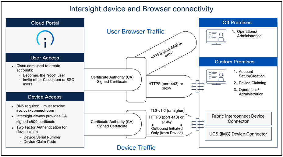
Connection to Intersight services with the Cisco UCS device connector
The Intersight platform separates user and device traffic and communicates using industry-standard HTTPS and TLS protocols.
All data exchanged between devices and the Intersight platform uses industry-standard encryption and security protocols. Connected devices use Transport Layer Security (TLS) with restricted ciphers and HTTPS on the standard HTTPS port 443. All data sent to Intersight is encrypted using the Advanced Encryption Standard (AES) with a 256-bit, randomly generated key that is distributed with a public-key mechanism. In addition, every device connection to the portal is authenticated with a cryptographic token so that only legitimate devices can be managed, thus closing a potential Trojan horse attack vector. All connections are initiated from the device. Thus, firewalls can block all incoming connection requests; only HTTPS port 443 needs to be enabled for outbound connections. As a result, firewalls do not need any other special configuration to enable Intersight connectivity. Devices can be configured to use HTTPS proxy servers to add an additional layer of security through indirection.
To help ensure connection security and prevent man-in-the-middle attacks, Cisco UCS devices connecting directly to the Intersight platform use a single-destination HTTPS URL. The platform presents a certificate signed by a Certificate Authority (CA). If an unsigned certificate is presented, the devices will not connect to the portal. Intersight software and the device connector create a secure management framework that provides real-time information related to device security. This approach also allows connected devices and Intersight software to stay synchronized with the latest connection-security updates.
To monitor and manage devices with the Intersight platform, they first must be claimed from an Intersight account. Devices can be claimed using a browser by going to the SaaS or virtual appliance portal and clicking on the Claim Devices tab. Device IDs and a claim code, both of which are unique to the device, are retrieved from the device.
You can find the device ID and claim code through the device’s local management interface. The claim code is refreshed every 10 minutes as an additional safeguard to ensure that the administrator claiming the device has physical access to it. Two-factor authentication is used to verify the identity and authenticity of each device being claimed. This authentication mechanism adds another layer of security to the device-claiming process. It requires access to the device as well as device identification information that is validated against your Intersight account.
If an unauthorized user guesses or learns device information, the user cannot claim a device without physical access to the device.
Cisco Intersight Assist is a virtual machine that you can deploy in your data-center environment to streamline some Intersight device-connection options. Intersight Assist helps you add endpoint devices to Cisco Intersight. A data center can have multiple devices that do not connect directly with Cisco Intersight. Any device that is supported by Cisco Intersight, but does not connect directly with it, will need a connection mechanism. Cisco Intersight Assist provides that connection mechanism and helps securely connect local data-center resources (VMware, storage, networking, etc.) to Cisco Intersight.
Cisco Intersight Assist helps you add endpoint devices to Cisco Intersight. A data center could have multiple devices that do not connect directly with Cisco Intersight. Any device that is supported by Cisco Intersight but does not connect directly with it, will need a connection mechanism. Cisco Intersight Assist provides that connection mechanism and helps you add devices to Cisco Intersight.
Cisco Intersight Assist enables Cisco Intersight to communicate with targets that do not have a direct path to Cisco Intersight and do not have an embedded Intersight device connector. These include targets such as storage devices, hypervisor managers, application performance management products, and much more. Intersight Assist communicates with the target’s native APIs and serves as the communication bridge to and from Cisco Intersight. Intersight Assist services run as a standalone appliance when used with Cisco Intersight SaaS. For the Intersight Connected Virtual Appliance and Private Virtual Appliance, a separate Assist Appliance is not needed because the services are collocated.
You can view the Intersight Assist details by navigating to Appliance UI > Target. You can choose to install Cisco Intersight Assist from the installer during the set-up wizard. It can be installed on an ESXi server, a Kernel-Based Virtual Machine (KVM), or a Hyper-V Hypervisor.
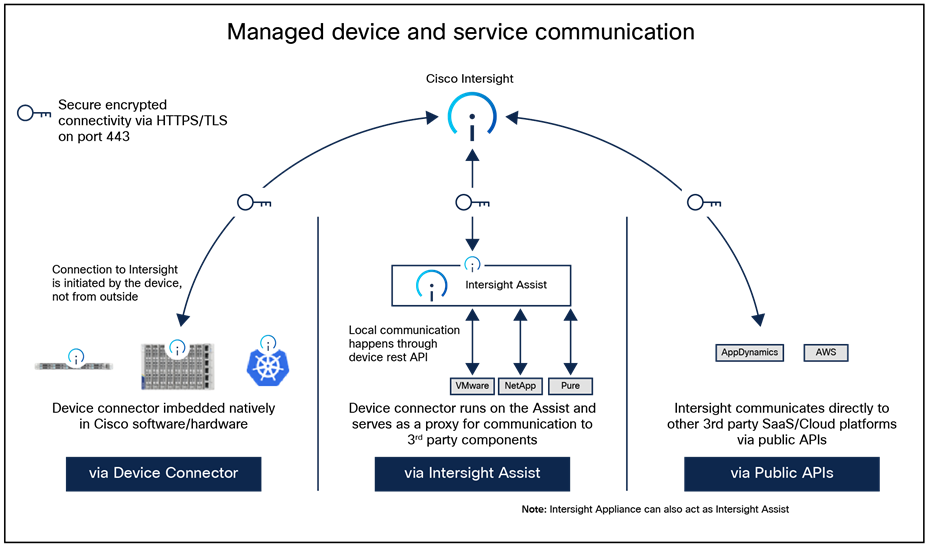
Managed device and service communications to Intersight
Configure fabric interconnects for Cisco Intersight management
During initial configuration of a fabric interconnect–based UCS system, you are given the option to run in UCSM mode (UMM) or Intersight Managed Mode (IMM). For Cisco UCS X-Series systems, IMM is the only supported mode.
Here we cover fabric-interconnect configuration for IMM and the appropriate selections for getting the system set up with secure passwords and updating the firmware to remediate any known bugs or CVEs. Depending on the state of each fabric interconnect, this first set of steps may not be necessary. If you see a message “Switch can now be configured from GUI,” as shown in the following image, you must follow these steps:
IMM configuration from console
Press CTRL-c, as instructed on the screen, to halt the GUI configuration process. You can configure Cisco Intersight mode only through the console.
Next, type “X” followed by Enter. Because of screen wrapping, you may not be able to see the “X.”
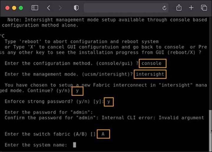
IMM configuration from console part 2
● You will be asked to enter the configuration method. You can configure Cisco Intersight mode only through the console. Type “console”.
● For the management mode, type “Intersight”.
● The wizard will ask you to confirm that you are setting up a new fabric interconnect in Intersight Managed Mode. Type “y” to confirm.
● You will be asked whether to enforce strong passwords. Select to enforce strong passwords and enter the password.
Next, configure the switch fabric.
● For the switch fabric (A or B), choose “A”.
● Name the system. (Note that the name assigned to the system in this step will be applied to every chassis and server connected to it. This name cannot be changed later without erasing the fabric interconnect configuration.)
● Enter the IP address for fabric interconnect A.
● Enter the netmask for the management network.
● Enter the default gateway for the management network.
● Enter the IP address of the Domain Name System (DNS) servers.
● Configure the default domain name.
The last step is to confirm your settings. Verify that your settings are correct and type “yes” to continue. It will take several minutes for the fabric interconnect to reboot. Before configuring the second fabric interconnect, wait until fabric interconnect A fully reboots. Once the first fabric interconnect has rebooted, the second fabric interconnect will be able to detect the first fabric interconnect’s presence and will allow its configuration as a cluster. Proceed to the next section to configure the second fabric interconnect.
You may need to hit the Enter key to wake up the console for fabric interconnect B (FI-B). If you see nothing on the screen, the fabric interconnect is waiting for you either to configure it from the GUI or to press CTRL-c to interrupt the process. Just as you did for the fabric interconnect-A setup, press CTRL-c.
● Type “X” and then Enter.
● Enter “console” for the configuration method.
● Fabric interconnect B should detect that its peer (fabric interconnect A) is already configured and will ask if it should attempt to join that cluster. Type “y” and hit Enter.
● Enter the password you used for fabric interconnect A.
At this point, fabric interconnect B will pull the networking configuration from its peer. You only need to provide fabric interconnect B with an IP address.
Type “yes” to save the configuration and restart the fabric interconnect.
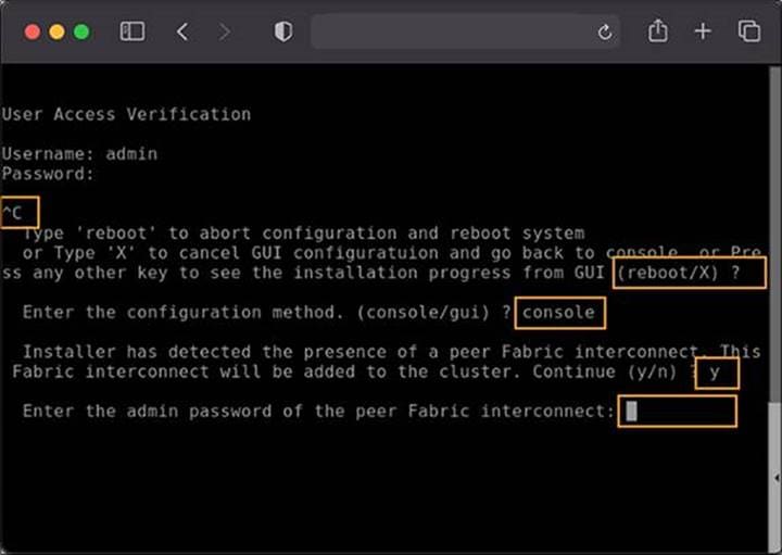
IMM configuration from console part 3
Multifactor claim process for fabric interconnects in the Cisco Intersight platform
Next, the system needs to be claimed in Intersight. Connect to the device console on the fabric interconnect pair. There is no longer an instance of Cisco UCS Manager, and when you browse to one of the fabric interconnects, you will be prompted to log into the device console instead. This console is where you obtain a device ID and claim code to claim this new domain in the Cisco Intersight platform.
Using a browser, connect the IP address of fabric interconnect. Ensure that HTTPS is used, or you will not be able to connect to the device console. Log in with the credentials you configured earlier during the fabric interconnect setup.
Device console log in
Select the Device Connector tab. If there is an error on this page saying, “Some unknown internal error has occurred,” it is likely because this domain has been claimed in Cisco Intersight already. Click the refresh button in the device connector view. If the problem persists, contact Cisco Technical Assistance Center (Cisco TAC) to address this problem. If, instead, you see a screen like the one shown below, which shows that the fabric interconnect can connect to Cisco Intersight but is not yet claimed, then proceed to the next step.
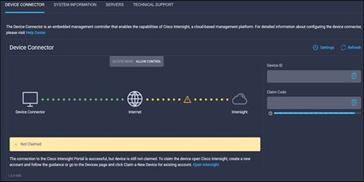
Connect the fabric interconnects to Intersight
Browse to intersight.com from your computer. Use your Cisco Intersight credentials for an account that has at least the “Device Technician” role. The roles “Device Technician” and “Device Administrator” allow you to claim and unclaim devices. Once authenticated, make sure you have selected “System” from the top drop-down menu, as shown below:
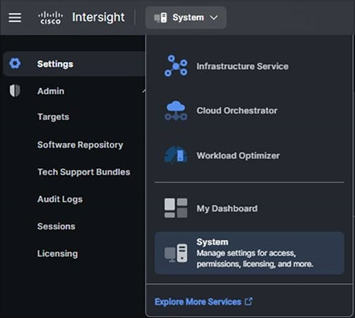
System view when claiming a device
● Select “Admin -> Targets” and then click the blue “Claim a New Target” button in the upper-righthand portion of the window.
● For target type, select “Cisco UCS Domain (Intersight Managed)” and click the “Start” button.
● Enter the device ID and claim code from the Device Console.
● Click the blue “Claim” button after pasting the device ID and claim code. Shortly after the claim succeeds, the fabric interconnect device connector should show a status of “Claimed,” as shown in the following image:
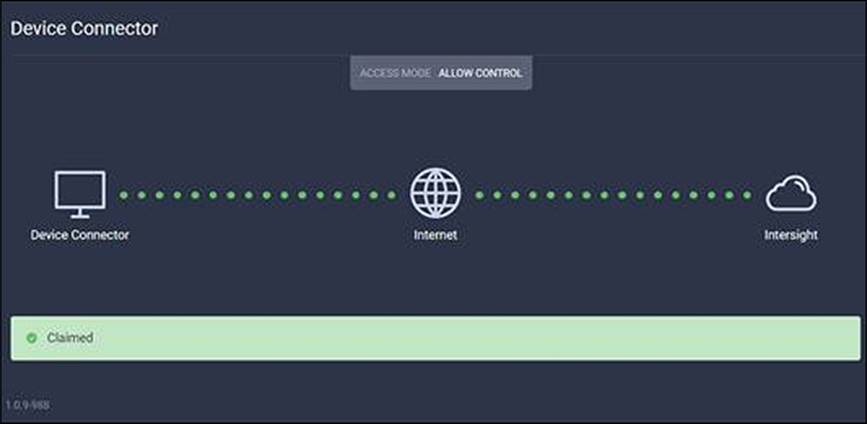
Device claimed
Although the “Device Technician” role can claim a target, the Device Technician cannot put that target into the right Intersight organization. Only an Account Administrator can do that. If your credentials do not have that privilege level, please reach out to someone within the Intersight organization who has Account Administrator credentials.
After the domain is claimed to Intersight, all configuration steps for servers, chassis, and fabric interconnects are initiated through Intersight.
For more information about Intersight-managed domains, refer to the Cisco Intersight Managed Mode Configuration Guide.
Cisco Intersight Managed Mode Transition Tool
Cisco Intersight Managed Mode (IMM) Transition Tool helps bootstrap new IMM deployments by replicating the configuration attributes of existing Cisco UCS Manager (UCSM) and Cisco UCS Central infrastructure and by converting the existing service profiles and templates to IMM server profiles and templates to accelerate deployment of new servers and to migrate existing servers to Intersight Managed Mode.
The IMM Transition Tool can also be used to clone configurations between Intersight accounts, including SaaS, Connected Virtual Appliance, and Private Virtual Appliance. IMM Transition Tool Release 3.0.1 and later provides support for preserving the configuration identifiers that a physical server gets from a server profile. These include IP addresses, MAC addresses, iSCSI Qualified Names (IQNs), Universal Unique Identifiers (UUIDs), World-Wide Node Name (WWNNs), and (World-Wide Port Names (WWPNs). This support enables the migration of service profiles from UCS Manager/Central to IMM.
With IMM Transition Tool Release 4.0.1 onward, you can use the software repository feature to install operating-systems and upgrade firmware on your servers.
IMM Transition Tool offers the following functionality:
● Ability to validate hardware compatibility for Cisco UCS Manager domain
● Fetching an entire configuration from a running UCS Manager domain or UCS Central instance
● Ability to validate what part of the configuration is available in Intersight
● Performing conversion of UCS Manager or UCS Central configuration attributes to IMM
◦ Conversion of the running configuration of the UCS Manager domain is primarily done in two parts (you can selectively enable or disable each section for configuration conversion):
◦ Convert the fabric configuration of the UCS Manager domain, including VLANs/VLAN Groups/VSANs, Port roles, QoS, and administrative settings (NTP/DNS/SNMP/SYSLOG)
◦ Convert the service profiles and service profile templates from the UCS Manager domain and all the attached policies
◦ Conversion of the running configuration of the UCS Central instance is primarily done as follows (you can selectively enable or disable each section for configuration conversion):
◦ Convert the service profiles and service profile templates from the UCS Central instance and all the attached policies.
Access methods to management and configuration interfaces
The management plane consists of functions that achieve the management goals of the system. Any management function undertaken by the user must rely on interaction through secure protocols. This is handled through HTTPS for any Intersight UI access. Authenticated, tokenized access is used for in-house development through APIs. Management security also entails role-based access control as well as auditing and logging of system activities and user input, all of which are incorporated into every management mechanism.
Single Sign-On (SSO) authentication enables you to use a single set of credentials to log into multiple applications. With SSO, you can log into Intersight with your corporate credentials instead of your Cisco ID. Intersight supports SSO through SAML 2.0, acts as a Service Provider (SP), and enables integration with Identity Providers (IdPs) for SSO authentication.
Multifactor Authentication (MFA)
With the implementation of Cisco Duo, multifactor authentication is performed through a Duo-authentication proxy, which is an on-premises software service that receives authentication requests from your local devices and applications through RADIUS or LDAP. It optionally performs primary authentication against an LDAP directory or RADIUS authentication server and then contacts Duo to perform secondary authentication. Once the user approves the two-factor request, which is received as a push notification from Duo Mobile, or as a phone call or other notification, the Duo proxy returns access approval to the device or application that requested authentication.
To log in to Cisco Intersight with Multi-Factor Authentication (MFA), navigate to id.cisco.com, go to the Security tab, and enable the MFA toggle button, or within Intersight itself, go to Settings > Cisco ID and enable the Two-Step Authentication option if you are using the Cisco ID login. If your organization uses Single Sign-On (SSO), you’ll log in through your Identity Provider (IdP), which will handle the MFA prompt as part of the SSO process.
For direct Cisco ID login:
1. Enable MFA in your Cisco ID profile:
2. Log in to id.cisco.com.
3. Go to the Security tab.
4. Find and enable the Multi-Factor Authentication (MFA) or Two-Step Authentication toggle button for your account.
Set up your authenticator application:
1. Follow the on-screen instructions to set up your preferred authenticator application (such as Google Authenticator) or another method for receiving MFA codes.
2. Scan the QR code with your application and enter the generated code to verify the setup.
When logging into Intersight:
1. Use your Cisco ID: Go to the Intersight login page or your specific Intersight SSO page.
2. Enter your credentials: Enter your Cisco ID email and password as usual.
3. Complete the MFA prompt: You will then be prompted to enter a code from your authenticator app or approve a push notification, depending on your setup.
For Single Sign-On (SSO) users:
1. Use the SSO URL: Access the Cisco Intersight SSO page provided by your organization.
2. Log in using your Identity Provider (IdP): You will be redirected to your organization’s IdP (for example, Azure AD, Okta) to log in.
3. Complete the MFA prompt: Your IdP will then present its own MFA challenge, which you’ll complete to gain access to Intersight.
Single sign-on with Intersight
Single Sign-On (SSO) authentication enables you to use a single set of credentials to log into multiple applications. With SSO, you can log into Intersight with your corporate credentials instead of your Cisco ID. Intersight supports SSO through SAML 2.0, acts as a Service Provider (SP), and enables integration with identity providers (IdPs) for SSO authentication. User authentication and role-based access control Intersight accounts form the authentication domain for users. The accounts control all resource access, and authenticated users are restricted from seeing any data in accounts where they are not authorized. With the SaaS platform, Cisco login IDs can be used for authentication with the identity provider for Cisco.com, which includes support for multifactor authentication. Both SaaS and on-premises Intersight implementations allow integration with external identity management systems to meet existing customer authentication requirements.
The Cisco Intersight framework uses granular access control with privileges managed per resource. Intersight software allows configuration of users and groups into several roles, and each user or group can be a member of multiple roles. Roles implemented include the following privileges:
● Account administrator: full control and management capabilities for the Cisco Intersight account and devices under management
● Read-only: read-only visibility to resources under management
● Device technician: administrative device actions including device claim to a Cisco Intersight account
● Device administrator: administrative device actions including device delete from a Cisco Intersight account
● Server administrator: server lifecycle and policy-based management
● User access administrator: user, group, and identity-provider configuration
What management interfaces are available after IMM for FI based systems?
Once your system is configured for Intersight Managed Mode, the UI for UCSM is not available. If you connect to either fabric interconnect, you will be presented with a UI login screen that gives you access to a device connector control UI. This UI is for recovery purposes only and has no other management capabilities.

The FI UI only has a Device Console management capability in IMM and is designed for recovery and troubleshooting only.
Connecting to the CIMC management IP of the server with a browser using HTTPS will present you with a KVM login screen. This is also for recovery purposes only and has no other management capabilities.
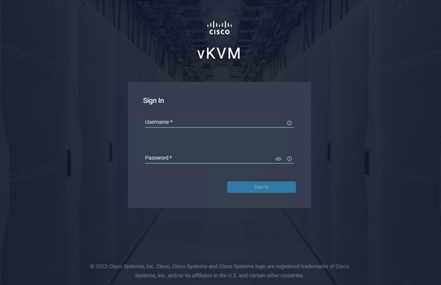
The CIMC UI in IMM is a vKVM for server recovery and troubleshooting purposes only.
The fabric interconnect management IP and addresses have only a rudimentary SSH console for troubleshooting purposes. SSH to the server CIMC IP is not available even though you are prompted for a password. You can view the CIMC firmware debug shell by SSH to the IMM fabric interconnect and typing: connect cimc 1/1 to go to the first system BMC restricted console. See debug shell screen shot in Figure 21 below.
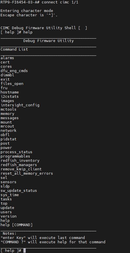
Accessing CIMC from the FI CLI for troubleshooting.
What interfaces are available for Cisco UCS standalone servers claimed by Intersight?
A Cisco UCS server in standalone mode, with no fabric interconnects, is technically not in Intersight Managed Mode (IMM) even if it is claimed by Intersight and managed therein. While management is still possible through Intersight, the server IMC is still available for direct UI access and SSH for management. It is recommended to choose only one management method in these scenarios to avoid any potential conflicts.
In a standalone Cisco UCS server in IMM with the device connector (DC) set to run with “full control from Intersight only,” the following CIMC functions are available:
● You can still access IMC settings from withing Intersight.
● With DC locked down to manage in Intersight only, direct access to CIMC in the browser is restricted.
● Secure LDAP cannot be used to log into CIMC from Intersight, but it can be used individually on each CIMC directly.
● If Intersight is not available, you can log into CIMC as local admin, but you cannot make any changes (access is “read only”).
● If, in standalone mode, Intersight is not available (that is, it has lost connectivity) for a longer than tolerable, you can unclaim from CIMC and login as local admin to administer the machine. You can reclaim again once connectivity is restored.
Intersight accounts form the authentication domain for users. The accounts control all resource access, and authenticated users are restricted from seeing any data in accounts where they are not authorized. With the SaaS platform, Cisco login IDs can be used for authentication with the identity provider for Cisco.com, which includes support for multifactor authentication. Both SaaS and on-premises Intersight implementations allow integration with external identity management systems to meet existing customer authentication requirements.
For the latest list of identity providers validated by Intersight, see Supported Systems. For more information on the SAML support provided by the Intersight SP, see Single Sign-On with Intersight.
Resource groups, organizations, roles
Privileges on endpoints are hierarchical based on user role, from a resource group, to organization, to individual user. The top-level distinction is resource groups, which are collections of managed resources; that is, target endpoints that have been claimed in the Intersight service.
Resource groups are divided between organizations in Intersight. This allows access and control by user domain and enables multitenancy. User roles and privileges are functional within an organization on the assigned resources.
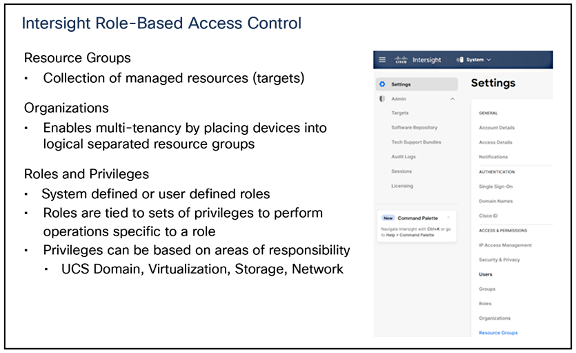
Resource groups Organizations Roles and Privileges
Account types and best practices
The following is a list of best practices around account creation and assignment:
● Each account should have multiple account-administrator users to ensure continuity, in the event an account administrator loses access to their account or is otherwise unavailable.
● Each account should have at least one Cisco CCO ID configured, even if SAML/IdP is configured for access.
◦ This enables users to access their account in cases when there are configuration issues that prevent logging in to Intersight using SSO.
● You can choose to use a service account as an account administrator instead of using a personal account. Activate multifactor authentication along with your Cisco ID for Intersight account access.
Intersight provides Role-Based Access Control (RBAC) to authorize or restrict system access to a user, based on user roles and privileges. A user role in Intersight represents a collection of privileges for operations that the user can perform and provides granular access to resources. Intersight provides role-based access to individual users or a set of users under resource groups.
A user represents an entity that can log into a specific role in Intersight with a Cisco ID or a single sign-on credential configured on Intersight. A user is granted write or read-only access to the required system resources only if the specific role grants the access privileges to the role. A privilege comprises a set of actions a user can perform. For example, a user with a server-administrator role can update server configurations, create and deploy a server profile, or perform server actions on the managed servers. However, the user cannot perform similar actions for a HyperFlex cluster.
A resource group represents a collection of users with a specific role, permission, and privileges to manage targets within one or more Intersight organizations. You can create multiple user groups to assign common roles and privileges to a set of users. If you make changes to a role or a privilege in a resource group, all users in the group inherit the same privileges.
A system-defined role is created by default in an account. Each system-defined role has only one privilege associated with it and allows a user to perform only a specific operation. These roles cannot be modified. For example, a device technician can only claim a target, but not perform any other operation.
A user-defined role is created to assign multiple privileges to a user to perform different operations. These roles can be modified by an administrator as required. For example, you can create a user-defined role named device user and assign both device-administrator and server-administrator privileges. The user can now perform both target-claim and server operations. To create a user-defined role, use the Create Role wizard.
Note: Only users with account-administrator or user-access-administrator privileges can create a user-defined role.
The Cisco Intersight framework uses granular access control with privileges managed per resource. Intersight software allows configuration of users and groups into several roles, and each user or group can be a member of multiple roles. Roles implemented include the following privileges:
● Account administrator: full control and management capabilities for the Cisco Intersight account and devices under management
● Read-only: read-only visibility to resources under management
● Device technician: administrative device actions, including claiming a device to a Cisco Intersight account
● Device administrator: administrative device actions, including deleting a device from a Cisco Intersight account
● Server administrator: server lifecycle and policy-based management
● User access administrator: user and identity-provider configuration. Please see the Intersight help pages for specifics on managing roles and resources
Account settings can be adjusted by selecting the user (person) symbol in the top right of the Intersight UI and then selecting the account in the drop-down menu. You will be taken to a settings UI where you can press the “Configure” button in the top right to adjust various account settings to keep in line with your company security policies for idle timeout, maximum sessions per user, etc.
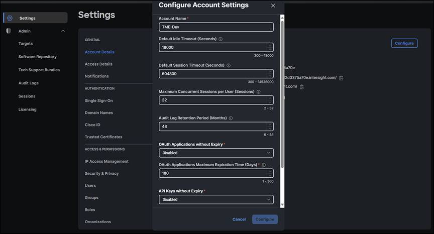
Adjust account session and other security settings
Through policy we get security enforcement
Intersight provides various policies that help enforce a secure deployment posture within service profiles:
● Unified port policies: these policies define the configuration for Ethernet and Fibre Channel ports, enabling administrators to set specific security-related parameters such as VLAN settings, port channel settings, QoS (Quality of Service) policies, etc.
● Server BIOS policies: these allow administrators to configure security-related settings in the server’s BIOS, such as enabling or disabling specific hardware features, setting passwords, enabling secure boot, or configuring Trusted Platform Module (TPM) settings.
● Local disk configuration policies: these govern how local disks are configured, encrypted, or formatted, providing security measures for data stored on local disks.
● Boot security policies: these control boot-related security settings, including secure-boot configurations and control over boot devices.
● Maintenance policies: these define maintenance windows and policies that can help enforce security-related updates or configurations during specified maintenance periods.
● Role-Based Access Control (RBAC): this allows administrators to define roles and privileges, ensuring that only authorized personnel have access to critical functions and configurations, enhancing security by limiting access based on job responsibilities.
By utilizing these policies within Intersight when creating and managing server profiles, organizations can establish a more secure deployment posture, ensuring that servers are provisioned and configured according to predefined security best practices and policies. This helps in reducing potential vulnerabilities and maintaining a standardized and secure computing environment within the Cisco UCS infrastructure.
To use a policy in a server profile:
1. Create or edit an existing server profile.
2. Click on the “Policies” tab.
3. Select an existing policy from the list or create a new one by clicking “Create Policy.”
4. Configure the policy settings as needed.
5. Apply the policy to the server profile by clicking “Assign Policy.”
Once you have assigned a policy to a server profile, Intersight will automatically apply the configuration settings to the server. You can also use policies to stage changes and then activate them at a later stage.
The benefits of using policies in server profiles include:
● Consistency: ensure that multiple servers have the same configuration settings
● Efficiency: apply configurations to multiple servers with a single policy assignment
● Flexibility: easily modify or update a policy and apply it to multiple servers
When logged into the Intersight UI, select “Infrastructure Service” from the top drop-down menu. In the left navigation pane, you can select “Polices.” Here you get a list of policies that have already been created. You can edit an existing policy by selecting it, or you can select the “Create Policy” button at the top right of the screen (see Figure 23) to create a new one. It is through this wizard that you will select your policy type and create policies as needed.
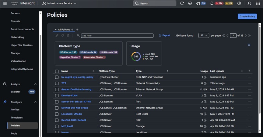
Policies in your organization
When creating a new policy, select the type and complete the wizard to enter the policy parameters.
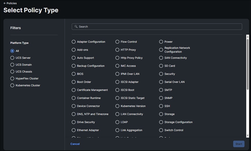
Select policy type
Server profiles and policies in Cisco UCS with intersight
A server profile is a software definition of a server and its LAN and SAN connectivity. The profile defines a single server and its storage and networking characteristics. It is constructed through the configuration settings defined in polices that you create. Server profiles are stored in Intersight and automatically configure the server, adapters, fabric extenders, and fabric interconnects to match the configuration specified in the service profile. This automation of device configuration reduces the number of manual steps required to configure servers, Network Interface Cards (NICs), Host Bus Adapters (HBAs), and LAN and SAN switches.
The server profile is a central component that defines the compute, network, and storage characteristics for a server within the UCS infrastructure. Essentially, it abstracts the physical hardware configuration from the logical configuration, enabling rapid provisioning, mobility, and scalability within the data-center environment. It is critical to note that policies prevent systems from being tampered with physically because changes to local settings are blocked when a policy is applied. This makes drift management nearly moot since the application of a policy prevents drift in the first place. See Appendix C for recommended policy configuration settings.
A server profile contains:
● Hardware identity: this includes details such as WWPN (World-Wide Port Name) and WWNN (World-Wide Node Name) for Fibre Channel, MAC addresses for Ethernet, BIOS settings, and firmware versions.
● Boot policies: these define how the server boots, which operating system it uses, and where it boots from (local disk, SAN, LAN, etc.).
● Host firmware package: this specifies the firmware versions to be applied to the server’s components, ensuring consistency and compliance.
You can create server profiles using the server profile wizard, or you can import the configuration details of Cisco UCS C-Series servers in standalone mode and fabric-interconnect-attached servers in Intersight Managed Mode (IMM) directly from Cisco Integrated Management Controller (IMC). You can create server profiles using the server profile wizard to provision servers, create policies to ensure smooth deployment of servers, and eliminate failures that are caused by inconsistent configuration. The server profile wizard groups server policies into the following four categories to provide a quick summary view of the policies that are attached to a profile:
● Compute policies: BIOS, boot order, and virtual media
● Network policies: adapter configuration, iSCSI boot, LAN connectivity, and SAN connectivity policies
◦ The LAN connectivity policy allows you to create Ethernet network policy, Ethernet network control policy, Ethernet network group policy, Ethernet adapter policy, or Ethernet QoS policy. When you attach a LAN connectivity policy to a server profile, the addresses of the MAC address pool, or the static MAC address, are automatically assigned.
● Storage policies: SD card and storage policies
● Management policies: device connector, IPMI over LAN, LDAP, local user, network connectivity, SMTP, SNMP, SSH, serial over LAN, syslog, NTP, certificate management, and virtual KVM policies
● See IMM Security Policy Checklist and Intersight Help for recommended policy configuration settings.
To create a server profile, select “Infrastructure Service” from the top drop-down menu in the Intersight UI. Select “Profiles” from the left menu pane. You are shown a list of existing profiles that you can edit as needed.
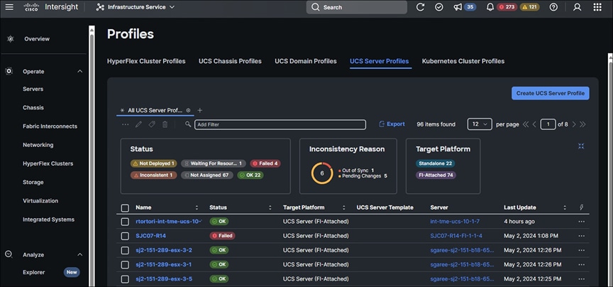
Profile list
You can create a new profile by clicking the “Create UCS Server Profile” button at the top right of the screen (see Figure 27).
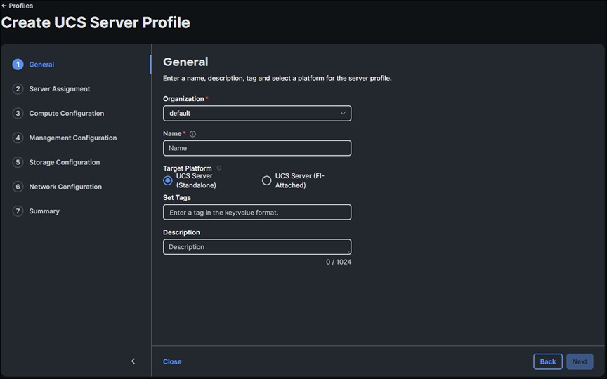
Create a new server profile
You can assign your profile to an existing server or bypass that step for now. You are then walked through policy categories for your profile, at which time you can assign or create policies.
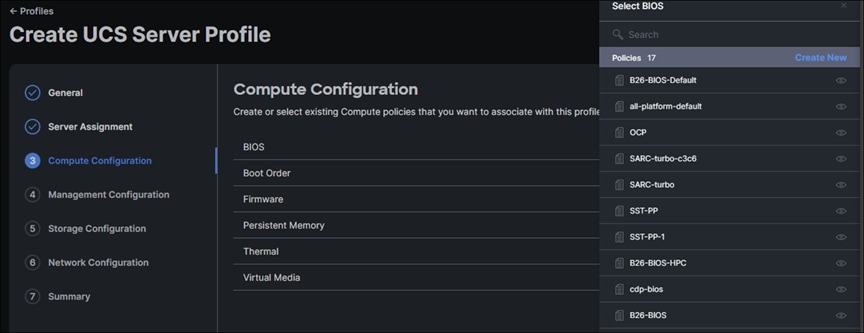
Assign or create a policy for compute configuration
Next you can set policies for management.
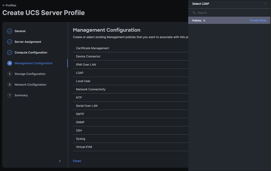
Set management policies
Similarly, you will set storage and network policies and then you will be presented with a summary.
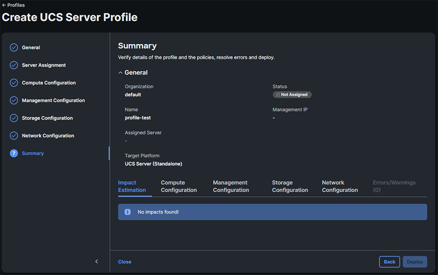
Profile summary
The assignment process is immediate. The profiles are assigned to the servers you have selected, but no configuration changes happen yet.
In Intersight, browse to “Configure -> Profiles” and select the “UCS Server Profiles” tab, and you will see that your profile(s) has been assigned to a server but shows a status of “Not Deployed.” You can select multiple profiles in this state, and click the ellipses at the top of the table to deploy them all in bulk. When you deploy a profile, Intersight will create a Request that you can monitor. Every time you make a change to a profile, or a policy associated with that profile, its state will change from “Deployed” to a state indicating changes that have been made within Intersight but have not been pushed to the server. Each time, you will have to come back to this screen and “Deploy” the profile. This behavior is different from that of Cisco UCS Manager. You can read more about the various states at: https://intersight.com/help/saas/features/servers/configure.
When ready to deploy the server profiles, click “Deploy” and then click “Deploy” again in the pop-up window:
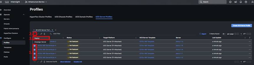
Deploy the service profile
In an environment where you have multiple UCS domains, you can move that profile between any of those domains.
It is recommended that you create a baseline service profile with your organization’s preferred security settings. You can create a “default” resource pool with an “every server” qualification/selection policy with no filters. This will include every server added to the resource pool. Then apply a server profile to that pool. This way you will end up with the automatic application of a default security profile policy to every server claimed in that Intersight account. You can clone and modify the baseline profile on as-needed basis for individual servers in the pool.
Firmware upgrades and image downloads
There is a difference in the IMM numbering convention between Cisco UCS X-Series firmware versions and IMM infrastructure versions. For example, infrastructure might have firmware version 4.2(3a), but the Cisco UCS X-Series firmware may be listed as 5.2. The IMM server and infrastructure firmware is much less coupled than the traditional UCSM firmware, as seen in the cross-version support tables. Server firmware can be more recent than infrastructure firmware, which makes firmware management easier because server bug or CVE fixes and new servers can be updated independently without forcing infrastructure upgrades.
Image downloads for firmware or appliances are signed. There is currently no mechanism to verify the MD5 hash of downloaded software in situ. Even though the checksum is not validated for the downloaded image, the signature on the image guarantees that it is valid, unmodified, and malware free. An image with a failed signature cannot be used.
Upgrading fabric-interconnect firmware
Before discovering what hardware is connected to the fabric interconnects, you should check to see if a recommended firmware upgrade is available for the fabric interconnects. After logging into Intersight, select the drop-down box in the upper left corner of the screen, and select “Infrastructure Service” if it is not currently selected (see Figure 31).
Selecting fabric interconnects
Select your fabric interconnect(s) from the list, click the three dots in the right column, and then select “Upgrade Firmware” from the drop-down menu.
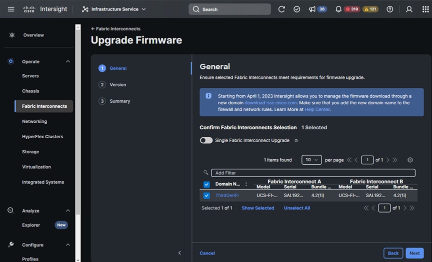
Select your fabric interconnect for upgrade
Click “Next”, then select your desired firmware version.
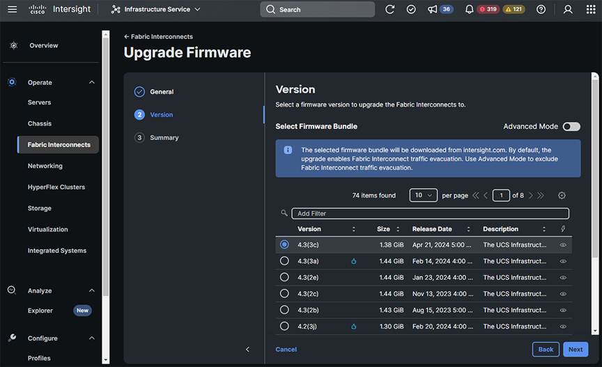
Choose your firmware version
Click “Next” again, then review the summary and commit the upgrade.
Intersight allows for upgrading firmware on multiple servers at once. In Intersight, browse to “Operate -> Servers”. Intersight will display the servers discovered in the domain.
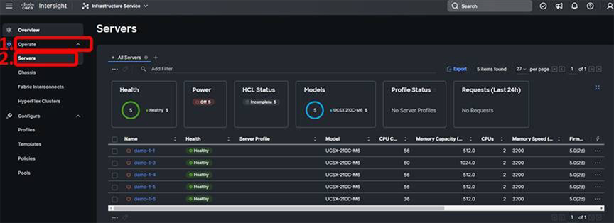
Choose your server for firmware upgrade
Select all the discovered servers that are of the same type by clicking the checkbox next to each one. Bulk firmware upgrade operations are supported only on similar servers. You can sort the servers table by “Model” if there is any confusion.
With one or more servers selected, click the ellipses s…) at the top or bottom of the server table and choose “Upgrade Firmware” (see Figure 35).

Select multiple of the same model to upgrade
The first step of the firmware upgrade process introduces the firmware upgrade wizard and allows you to change your mind about which servers you want to upgrade. Click “Next” to proceed.
Next, select the upgrade firmware version.
You can view firmware details by selecting the “eye” button in the right column of the firmware.
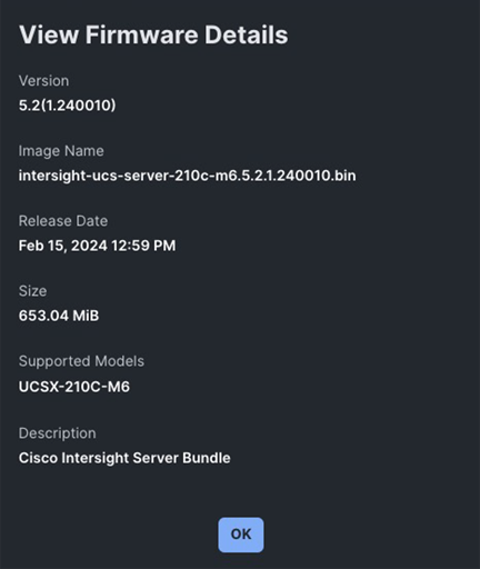
Firmware details
Select the radio button for the firmware version that best applies to your deployment then click “Next.” On the “Summary” page, verify that the information is correct and select “Upgrade”. Select “Reboot Immediately to Begin Upgrade” if the servers are at a state where it is safe to reboot, and click “Upgrade” again on the pop-up.
This process takes roughly 30 minutes, and the process can be monitored by selecting the active requests in the upper righthand portion of the screen.
Cisco Intersight includes an API that supports the OpenAPI specification, a powerful definition format to describe RESTful APIs. Support for the OpenAPI specification provides access to an interoperable REST API with tools that automate the generation of the Intersight API documentation, API schemas, and SDKs. The Intersight API includes fully functional Python and PowerShell SDKs. See the “Audit records, scope, and use cases” section later in this document for a brief discussion of the API browser.
The REST architecture provides access to the Intersight Management information model. API requests may be read-only queries with no side-effects, or they may produce modifications of the resources. The response may confirm that some alteration has been made to the resource, and it may provide hypertext links to related resources or collections of resources. The Intersight API accepts and returns messages that are encapsulated through JavaScript Object Notation (JSON) documents and securely uses HTTP over TLS as the transport protocol. The Intersight OpenAPI document is available with both OpenAPI schema versions 2 and 3. We recommend using the OpenAPI document based on schema version 3.
Intersight provides downloadable SDK packages in multiple programming languages. The Intersight API is automatically updated when new features are deployed to the cloud, providing programmatic access to new IT infrastructure capabilities.
API keys
API keys are created using an Intersight account, as described in the Intersight API Quick Start Guide. The Intersight Account Management (IAM) service for the account’s region manages the API key creation and lifecycle.
There are region-specific target URLs for API requests, and they must be accessible from the requesting client.
● North America region: intersight.com and us-east-1.intersight.com
● EMEA region: eu-central-1.intersight.com
Intersight API clients can be deployed anywhere if they have network connectivity to the Intersight service and can establish outbound HTTPs connections to the regional endpoints over TCP port 443. The Intersight API clients are not required to have network connectivity to the systems managed by Intersight. However, in some use cases such as bulk claiming devices, API clients may need connectivity to the region-specific Intersight URLs and managed systems.
You can also view the region-specific target URLs in the API documents:
1. Log into your Intersight account at https://intersight.com.
2. Go to “Help > Command palette > API docs”.
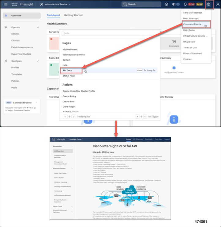
API documents
Intersight rediscovery and decommissioning
Rediscovery and decommissioning of a chassis or server can be done in IMM-managed devices. Both operations are important to accurately capture new hardware or to remove a system from service for disposal or repurposing.
For a server, select the server link from the Infrastructure Services’ left navigation menu, then select your device. Click the ellipses (…), then “System” in the drop-down menu. From here you can choose various options, including “Rediscover” and “Decommission.”
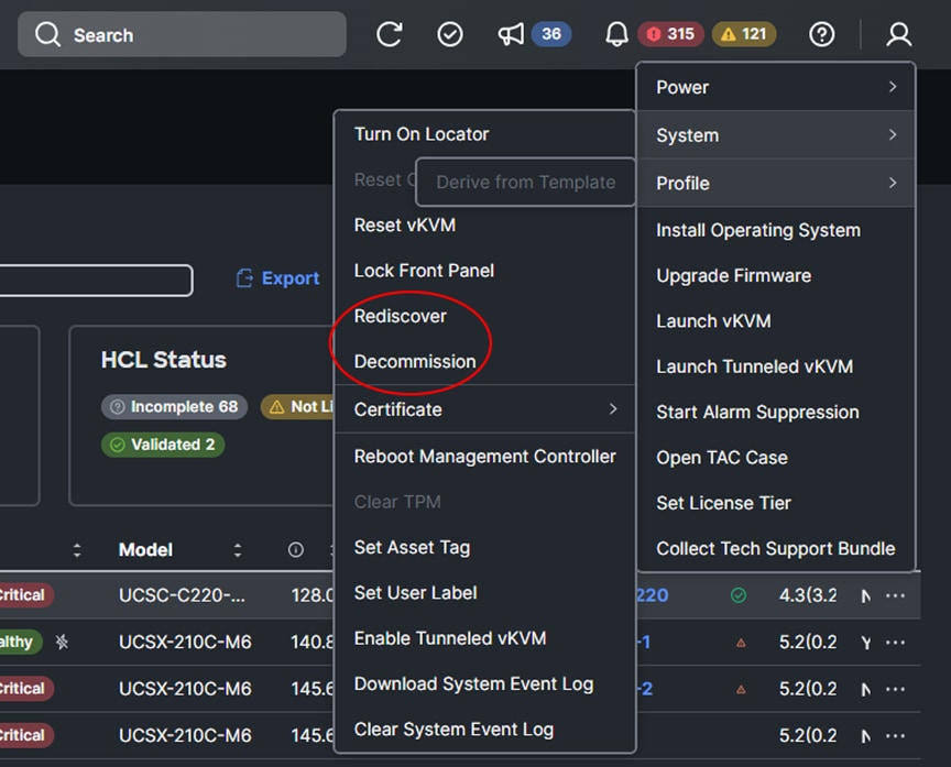
Rediscover or decommission a server
For a chassis, select the chassis link from the Infrastructure Services’ left navigation menu, then select your device. Click the ellipses (…) in the drop-down menu. From here you can choose various options, including “Rediscover,” “Decommission,” and “Remove.”
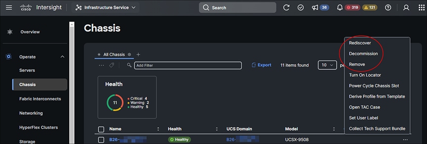
Rediscover, decommission, or remove a chassis
Chassis: rediscovery rebuilds the connection list between I/O cards and fabric interconnects. This action would trigger a workflow to update the connection information of both the I/O cards or intelligent fabric modules of the chassis and the fabric interconnects. If the connections have not changed, this operation will not impact service.
Rediscovery of a chassis can be executed from:
● Chassis list view -> Rediscover
● Chassis detailed view -> Actions -> Rediscover
● Fabric interconnect details -> Connections -> Chassis -> … -> Rediscover
Server: rediscovery rebuilds the inventory of the server if any modules in the server were replaced, added, or removed. Rediscovery is also required to rebuild the server inventory if a server has been moved from another slot or chassis, or replaced. This action would trigger a workflow to retrieve the latest server inventory and location (chassis or slot, or rack-ID) and update the inventory. There would be an alarm indicating that a rediscovery needs to be performed.
Rediscovery does not normally impact service, especially if nothing in the server has been changed. We recommend, however, performing any of these actions in a maintenance window.
Rediscovery of a server can be executed from:
● Server list view > System > Rediscover
● Server detailed view > Actions > System > Rediscover
● Fabric Interconnect details > Connections > Servers > … > System > Rediscover
● Chassis detailed view > Inventory > Servers > … > System > Rediscover (This option is for blade servers only.)
Decommissioning removes a server or chassis and IOM inventories. A decommissioned chassis is likely to be eventually recommissioned. Part of the chassis information, including the chassis ID, is retained by Cisco Intersight. Decommissioning is performed when a server or chassis is physically present and connected, but you want to temporarily remove it from the Cisco Intersight configuration.
Remove—removes from Cisco Intersight the configuration of a chassis that has been physically removed. Before physically removing a chassis from the system, ensure that you unconfigure the server ports to which the chassis is connected. If you need to add a chassis that was earlier removed, back to the Cisco Intersight configuration, the chassis must be reconnected and then rediscovered. During rediscovery, Cisco Intersight will assign the chassis a new ID that may be different from ID that it was assigned earlier.
Recommission—brings the server or chassis and IOM back online and initiates the discovery process and then the inventory process. After this action is complete, you can access the server or chassis and any servers in it.
A list of decommissioned chassis is available in the “Devices” area under “Fabric Interconnects > Fabric interconnect name > Connections > Decommissioned.”
When you recommission the chassis, you have the option to configure the chassis ID.
Securely decommissioning a system
The discussion on system decommissioning here is distinct from the Intersight decommissioning discussed in the previous section.
Securely decommissioning a server is a critical process to ensure that sensitive data is properly handled, and the server is retired in a way that minimizes the risk of data breaches or unauthorized access. Failing to decommission a server securely can lead to data exposure, legal and regulatory issues, and potential harm to an organization’s reputation. Below are the levels of importance and the methods for securely decommissioning a server and its data.
Decommissioning a system or components of a system–specifically, the drives–requires special considerations in many circumstances. It is not sufficient to simply remove a drive or rotate a system out of production without sanitization. For older versions of UCS firmware, there are third-party applications that will run NIST-approved sanitization routines on plain-text drives or encrypted drives. The Commission Regulation (EU) 2019/424 requires that data be securely disposed of. Secure data disposal is accomplished by using commonly available tools that erase the data from the various drives, memory, and storage in Cisco UCS servers and reset them to factory settings. You must be familiar with what devices are present in your UCS server and run the appropriate tools for secure data deletion. In some cases, you may need to run multiple tools.
Beginning early 2024, UCS firmware supports disk and system sanitization. This can more appropriately be termed data sanitization. Cisco IMC supports this NIST 800-88-compliant data-sanitization feature. Using the data sanitization process, Cisco IMC erases all sensitive data, thus making extraction or recovery of user data impossible. As Cisco IMC progresses through the erase process, the status report is updated. You can check the status and progress of the data-sanitization process for each individual device erased from the report. Cisco IMC reboots when the data-sanitization process is completed and generates a report.
The erase process for data sanitization is performed in the following order on the server components:
1. Storage
2. VIC
3. BIOS
4. Cisco IMC
You can choose to either perform data sanitization on all the server components or select only storage and VIC components for data sanitization.
Proper decommissioning reduces the risk of data breaches. If data is not securely wiped, deleted, or destroyed, it may be accessible to unauthorized individuals who can exploit it for malicious purposes.
Secure decommissioning is essential for compliance with data-protection and privacy regulations. Many regulations, such as GDPR or HIPAA, require organizations to safeguard data even during disposal. It also serves to protect an organization’s intellectual property.
Additional procedural steps can be taken as well. These include physical destruction and environmentally responsible recycling of components where appropriate. If this is not possible because the systems will be reused, other things can be done such as disabling and removing all user accounts and resetting server configurations.
Secure decommissioning is a comprehensive process that involves technical, procedural, and organizational measures. By following these methods, organizations can minimize the risks associated with retiring servers and ensure that sensitive data is handled responsibly and securely.
Secure Erase allows you to initiate a workflow to delete all data from the server. This includes data on the BIOS, Baseboard Management Controller (BMC), Nonvolatile RAM (NVRAM), Dual In-line Memory Module (DIMM), embedded Multi Media Card (eMMC), Virtual Interface Card (VIC), and storage disks components (except remote Logical Unit Numbers [LUNs]). During this time, disruptive server actions, such as power actions, OS installation, firmware upgrades, decommissioning, and server profile deployment are disabled.
You can initiate the Secure Erase by clicking the ellipsis (…) icon in the Servers Table View of the desired server. Depending on the disk capacity, Secure Erase may take several hours to more than a day to complete. You can monitor the progress of the Secure Erase from the Requests tab.
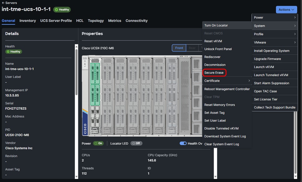
Server Secure Erase for full data sanitization
Note: To initiate the Secure Erase action, a minimum privilege level of Account Administrator or Server Administrator is required.
Insufficient space in the Fabric Interconnect cache can cause execution errors or failure of the Secure Erase. Clear the Fabric Interconnect cache to resolve space issues, then retry the action.
Warning:
● This action will permanently delete all data from the server. This data will not be recoverable.
● If Secure Erase is terminated before it is complete, data or drive corruption may occur.
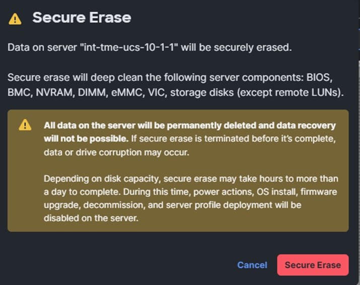
The Server Secure Erase warning message.
Secure Erase is supported on UCS series M5 and later servers. This action adheres to EU Lot 9 regulations for data storage devices and meets NIST SP 800-88 standards for data sanitization.
Depending on the disk capacity, Secure Erase may take several hours to more than a day to complete. See the table in the Intersight Help Center to get the estimated time required to complete a Secure Erase operation.
The following limitations are associated with Secure Erase:
● Secure Erase on VIC cannot be performed from Cisco Integrated Management Controller (CIMC) on B-series Servers.
● The M6 eMMC does not comply with the data sanitization requirements of EU Lot 9 Regulation.
● Secure Erase is unable to completely erase FlexUtil in C-series servers and FlexFlash partitions, including the Hypervisor, on B-series servers.
● Secure Erase may fail due to faulty components such as NVDIMMs and disks. You can remove the faulty component and retry.
● Standalone servers lose their network configuration and Intersight connectivity after a Secure Erase operation.
Scrub is typically used in server decommissions that will result in re-use of the system. It is distinct from the data sanitization in server secure erase discussed above. This policy determines what happens to local data and to the BIOS settings on a server during the discovery process, when the server is re-acknowledged, or when the server is disassociated from a service profile.
Local disk scrub policies apply only to hard drives that are managed by Intersight and do not apply to other devices such as USB drives.
Depending upon how you configure a scrub policy, the following can occur at those times:
Disk scrub
One of the following occurs to the data on any local drives on disassociation:
● If enabled, deletes initial 200MB of data from master boot record or the boot sectors, thus preventing the system to boot from an already installed OS if any. For secure deletion of data on drives, refer to the UCS Secure Data Deletion for Commission Regulation (EU) 2019 /424 Users Guide.
● If disabled (default), preserves all data on any local drives, including local storage configuration.
For a server associated with a service profile, disk scrub occurs during disassociation, based on the scrub policy used in the service profile. For an unassociated server, disk scrub occurs during the server discovery process, based on the default scrub policy.
BIOS scrub
One of the following occurs to the BIOS settings when a service profile containing the scrub policy is disassociated from a server:
● If enabled, erases all BIOS settings for the server and resets them to the BIOS defaults for that server type and vendor.
● If disabled (default), preserves the existing BIOS settings on the server.
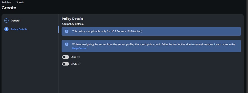
The Scrub Policy details showing Disk and BIOS selection options
Instant Secure Erase (ISE) drives
Instant Secure Erase (ISE) is a drive erasure method that provides a fast way to delete all data quickly when required. It encrypts the drive, and when it is time to permanently delete all data, only the encryption key has to be deleted. ISE is a super-set of non-cryptographic secure erase and utilizes encryption to make data unreadable. It contains the commands of non-cryptographic secure erase but also adds a “crypto” erase (CE) command, which can be utilized by both hard disks and solid-state drives if available. This method deletes the drive in a few seconds compared to a non-cryptographic secure erase, which writes over all the sectors and can take many hours. Only specific qualified ISE drives are available for use with Cisco UCS. See your Cisco representative for more information.
ISE drives securely erase all content on a disk in an unrecoverable, cryptographic manner.
● ISE is a super-set of non-crypto secure erase and utilizes encryption to make data unreadable.
● ISE contains the commands of secure erase but also adds a “crypto” erase (CE) command.
● Each disk creates a key that is used to encrypt/decrypt data as it is written or read.
● When the crypto command is accessed, the key is destroyed and all data on the disk is unable to be read. This happens instantaneously.
● Like SED secure erase, ISE only takes a few milliseconds to make the disk unreadable
● While ISE uses cryptographic techniques to securely erase data, it does not offer
data encryption to protect data at rest. SEDs are required for this, and they must be locked with a KEK solution.
Unclaiming will remove a system from Intersight. This is part of a more comprehensive decommissioning process for disposal or repurposing of a system. Log into Intersight with the account administrator, device administrator, or device technician privileges. From the “Service Selector” drop-down list, select “System. Navigate to Admin -> Targets.” Select the target to unclaim.

Unclaim a target
Once unclaimed, the target will no longer be available in Intersight. You can reclaim the device in the same way that you did originally if you wish to redeploy it.
Confidential computing at the hardware level
Confidential computing is a cloud-computing technology that isolates sensitive data in a protected CPU enclave during processing. The contents of the enclave — the data being processed and the techniques that are used to process it — are accessible only to authorized programming code and are invisible and unknowable to anything or anyone else, including the cloud provider.
A confidential computing-secure enclave refers to a protected and isolated environment within a computing system where sensitive data or operations can be securely processed or stored. This secure enclave ensures that the data within it is protected from unauthorized access, even from other parts of the system or privileged software layers.
Cisco UCS implements all processor vendor confidential computing capabilities from AMD and Intel. This includes trusted execution environments through secure enclaves as well as the various flavors of memory encryption. Implementation of these features is processor-dependent and chosen at build or purchase time.
You enable these features in Intersight by setting BIOS policies.

Create a BIOS policy
A complete list of BIOS tokens is available here:
For additional details, please see the Cisco Compute Security Overview white paper:
● Cisco Compute Security Overview White Paper
The concept of secure enclaves is primarily focused on maintaining the confidentiality, integrity, and privacy of sensitive information, especially when dealing with critical data or executing sensitive operations. These enclaves use hardware-based security mechanisms to create isolated and trusted spaces within the system’s memory or processing units, offering a high level of protection against various types of attacks, including those attempting to access or manipulate the enclave’s contents.
As company leaders rely more and more on public and hybrid-cloud services, data privacy in the cloud is imperative. The primary goal of confidential computing is to provide greater assurance to leaders that their data in the cloud is protected and confidential, and to encourage them to move more of their sensitive data and computing workloads to public cloud services.
For years, cloud providers have offered encryption services to help protect data at rest (in storage and databases) and data in transit (moving over a network connection). Confidential computing eliminates the remaining data security vulnerability by protecting data in use—that is, during processing or runtime.
How confidential computing works
Applications process data, and to do this, they interface with a computer’s memory. Before an application can process (encrypted) data, it must go through decryption in memory. Because the data is, for a moment, unencrypted, it is left exposed. It can be accessed, encryption-free, right before, during, and right after it has been processed. This leaves it exposed to threats such as memory dump attacks, which involve capturing and using Random Access Memory (RAM) that has been placed on a storage drive in the event of an unrecoverable error.
The attacker triggers this error as part of the attack, forcing the data to be exposed. Data is also exposed to root user compromises, which occur when the wrong person gains access to admin privileges and can therefore access data before, during, and after it has been processed.
Confidential computing fixes this issue by using a hardware-based architecture referred to as a Trusted Execution Environment (TEE). This is a secure coprocessor inside a CPU. Embedded encryption keys are used to secure the TEE. To make sure the TEEs are only accessible to the application code authorized for it, the coprocessor uses attestation mechanisms that are embedded within. If the system comes under attack by malware or unauthorized code as it tries to access the encryption keys, the TEE will deny the attempt at access and cancel the computation.
This allows sensitive data to stay protected while in memory. When the application tells the TEE to decrypt it, the data is released for processing. While the data is decrypted and being processed by the computer, it is invisible to everything and everyone else. This includes the cloud provider, other computer resources, hypervisors, virtual machines, and even the operating system.
Intel and AMD offer different technologies and approaches to achieve confidential-computing secure enclaves within their respective processor architectures. Below is a comparison between Intel’s technologies (SGX, TDX, and TME) and AMD’s features (SEV and SME) in terms of their approaches, functionalities, and key characteristics.
Intel’s technologies:
● Intel SGX (Software Guard Extensions): these create isolated secure enclaves within the CPU’s memory, allowing applications to protect sensitive code and data. This enables developers to create isolated execution environments for applications, protecting data and code even from higher-privileged software layers. It provides memory encryption, secure execution, remote attestation, and isolation.
● Intel TDX (Total Memory Encryption and Intel Trusted Execution Technology): this focuses on enhancing security in virtualized environments by providing memory encryption and secure execution environments for virtual machines. It provides total memory encryption, secure boot processes, and hardware-based isolation to protect against attacks in virtualized environments. Intel TDX protects VMs from unauthorized access and tampering, ensures secure migrations, and provides a trusted execution environment.
● Intel TME (Total Memory Encryption): this encrypts system memory to safeguard against unauthorized access, ensuring data confidentiality even if an attacker gains physical access to the memory. It protects system memory contents through encryption, ensuring data confidentiality and integrity. Intel TME aims to prevent data breaches and unauthorized access to memory contents.
AMD’s technologies:
● AMD SEV (Secure Encrypted Virtualization): this focuses on enhancing security in virtualized environments by providing hardware-based memory encryption for VMs. It offers memory encryption for each VM, isolating them from each other and the hypervisor, protecting against attacks in cloud environments. AMD SEV provides memory encryption, isolation, and facilitates secure VM migrations between physical hosts.
● AMD SME (Secure Memory Encryption): this encrypts the system’s memory, protecting against unauthorized access and physical attacks by encrypting memory contents. It encrypts system memory contents transparently without requiring specific software modifications, protecting against memory snooping attacks. AMD SME protects memory contents through encryption, enhancing security against physical attacks
Comparing the two, both Intel and AMD technologies aim to provide hardware-based security mechanisms to protect sensitive data and create secure enclaves. Intel SGX and AMD SEV focus on creating isolated execution environments for applications or virtual machines, whereas Intel TME and AMD SME concentrate on encrypting system memory to protect against unauthorized access.
Intel’s TDX is more tailored for virtualized environments, offering features for VM security, while AMD’s SEV is similarly focused on enhancing security in virtualized environments. Each technology has its unique characteristics, such as Intel SGX’s focus on secure execution or AMD SEV’s capabilities for secure VM migrations.
Overall, both Intel and AMD technologies contribute significantly to confidential computing by offering hardware-based security features, encryption mechanisms, and isolation to protect against various threats and attacks targeting sensitive data and applications. The choice between these technologies often depends on specific use cases, system requirements, and compatibility with the existing infrastructure.
Why use confidential computing?
In summary, confidential computing is critically important in server operations for the following reasons:
● To protect sensitive data, even while in use—and to extend cloud computing benefits to sensitive workloads. When used together with data encryption at rest and in transit with exclusive control of keys, confidential computing eliminates the single largest barrier to moving sensitive or highly regulated data sets and application workloads from an inflexible, expensive on-premises IT infrastructure to a more flexible and modern public-cloud platform.
● To protect intellectual property. Confidential computing isn’t just for data protection. The TEE can also be used to protect proprietary business logic, analytics functions, machine-learning algorithms, or entire applications.
● To collaborate securely with partners on new cloud solutions. For example, one company’s team can combine its sensitive data with another company’s proprietary calculations to create new solutions—without either company sharing any data or intellectual property that it doesn’t want to share.
● To eliminate concerns when choosing cloud providers. Confidential computing lets a company leader choose the cloud-computing services that best meet the organization’s technical and business requirements, without worrying about storing and processing customer data, proprietary technology and other sensitive assets. This approach also helps alleviate any additional competitive concerns if the cloud provider also provides competing business services.
● To protect data processed at the edge. Edge computing is a distributed computing framework that brings enterprise applications closer to data sources such as IoT devices or local edge servers. When this framework is used as part of distributed cloud patterns, the data and application at edge nodes can be protected with confidential computing.
The Confidential Computing Consortium
In 2019, a group of CPU manufacturers, cloud providers, and software companies—Alibaba, AMD, Baidu, Fortanix, Google, IBM/Red Hat, Intel, Microsoft, Oracle, Swisscom, Tencent, and VMware—formed the Confidential Computing Consortium (CCC) under the auspices of The Linux Foundation. Cisco Systems, Inc., is a member of the consortium.
The CCC’s goals are to define industry-wide standards for confidential computing and to promote the development of open-source confidential computing tools. Two of the Consortium’s first open-source projects, Open Enclave SDK and Red Hat Enarx, help developers build applications that run without modification across TEE platforms.
However, some of today’s most widely used confidential computing technologies were introduced by member companies before the formation of the Consortium. For example, Intel SGX (Software Guard Extensions) technology, which enables TEEs on the Intel Xeon® CPU platform, has been available since 2016; in 2018 IBM made confidential computing capabilities generally available with its IBM Cloud Hyper Protect Virtual Servers and IBM Cloud Data Shield products.
Secure data delivery and storage
Self-Encrypting Drives (SEDs) and drive-security policy
Data-at-rest encryption on a Cisco UCS server can happen in software for VMs (for example, Vormetric Transparent Encryption or Vmcrypt) or by the operating system (for example, Microsoft’s BitLocker). This can also be accomplished using hardware. To that end, Self-Encrypting Drives (SEDs) were developed and have many advantages. SEDs have a negligible impact on performance speed and latency. The encryption process is completely integrated into the drive, so there is no need for other system components to perform compute intensive encryption operations. SEDs are independent of the operating system, so even if a hacker attacks a computer, it is nearly impossible to access the SED (and the encryption keys stored within) when the computer is turned off.
In a Cisco UCS server, SEDs can utilize a remote key management solution. Remote key management is the recommended method for SED key management since it does not rely on stored or “remembered” pass phrases. The key-management software optimizes the SED’s decryption and encryption functions and key management, relieving the user of any active SED administration. Lastly, SEDs are inexpensive to deploy and maintain. SEDs are encrypted the moment they come off the assembly line. Management software does the rest, ensuring that SEDs do their job without the need for human intervention.
Self-Encrypting Drives (SEDs) have special hardware that encrypts incoming data and decrypts outgoing data in real-time. The data on the disk is always encrypted in the disk and stored in the encrypted form. The encrypted data is always decrypted on the way out of the disk. A media encryption key controls this encryption and decryption. This key is never stored in the processor or memory. Both Cisco UCS Manager and Intersight support SED security policies on Cisco UCS C-Series servers, B-Series M5/6/7 servers, X-Series servers, and S-Series servers.
SEDs must be locked by providing a security key. The security key, which is also known as a key-encryption key or an authentication passphrase, is used to encrypt the media-encryption key. If the disk is not locked, no key is required to fetch the data.
The encryption and decryption for SEDs is done through the hardware. Thus, it does not affect overall system performance. SEDs reduce disk-retirement and -redeployment costs through instantaneous cryptographic erasure. Cryptographic erasure is done by changing the media-encryption key. When the media-encryption key of a disk is changed, the data on the disk cannot be decrypted and is immediately rendered unusable. With Cisco UCS Manager Release 3.1(3), SEDs offer disk-theft protection for C-Series and S-Series servers.
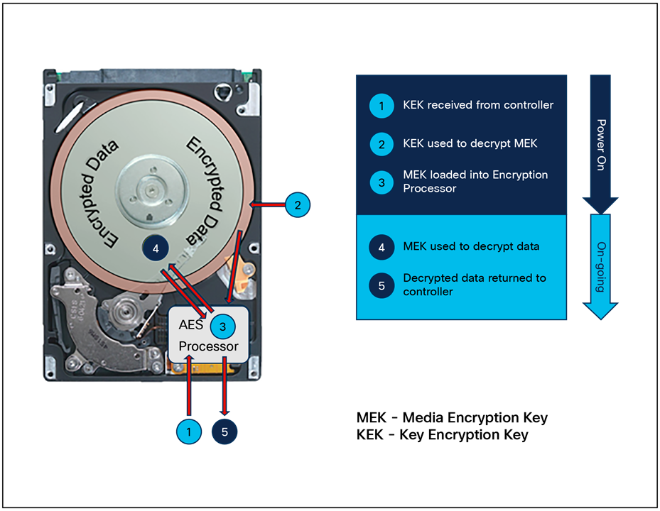
SED anatomy
Cisco Intersight enables you to configure remote security keys utilizing a third-party Key Management Server (KMS). The configuration for this is set in the drive security policy. You will need to create certificates and have the CA root certificate available to complete the process. We recommend that you work with your InfoSec team for this part of the deployment.
SED controller and drive states
Cisco Intersight reports on the security status of self-encrypting drives (SEDs) and the disk controller itself using security flags. These flags indicate the item’s current state regarding encryption and access.
The storage controller and disks have the following security flags:
● DriveSecurityCapable: indicates that the controller or disk is capable of supporting SED management.
● DriveSecurityEnabled: indicates that the controller is security-enabled, and disks in this controller can be further secured using the storage policy.
Note: Before you configure drive security, the controller flag will be set to DriveSecurityCapable. After you configure drive security, this status will change to DriveSecurityEnabled.
The following security flags are exclusive to storage disks:
● Locked: The drive, initially locked in the primary server, is transferred to the current server. To access the data, you must unlock the drive by either entering the manual security key or reconnecting to the original KMIP key management server.
● Foreign: The drive, previously configured with virtual drives in the primary server, is relocated to the current server. To preserve and access the original virtual drive data, you must import this configuration. If these virtual drives must be secured, you must unlock the physical drives before importing the foreign configuration.
● Unencrypted: The drive can be encrypted but is currently not encrypted.
● Unlocked: The drive is currently encrypted, but the data is accessible to the user unencrypted.
Important Notes:
● Initially, a secure-enabled SED shows a “drive state” as JBOD and the security flag of Unlocked when it is encrypted and not part of a virtual disk.
● Moving a secured drive to a new server will change the security flag to Foreign Locked.
● To resolve a locked SED, you must unlock it or perform a secure erase.
Tri-mode disk controller behavior
A microchip tri-mode disk controller is a drive controller capable of handling SAS, SATA, and NVMe drives. It is configurable to manage keys for SEDs and is required to enable and disable encryption. The following two conditions apply:
● Disabling security on the controller requires a reboot.
● Changing key mode from local to remote and vice versa is a destructive process. Any VDs must be removed and security must be disabled. A reboot is required.
Tri-mode controllers have a BIOS setting that enables or disables a controller password requirement. Note that the passphrase mentioned in Figure 48 is NOT the passphrase used to generate the local key encryption KEK; is the controller passphrase entered in the BIOS to secure the controller itself.
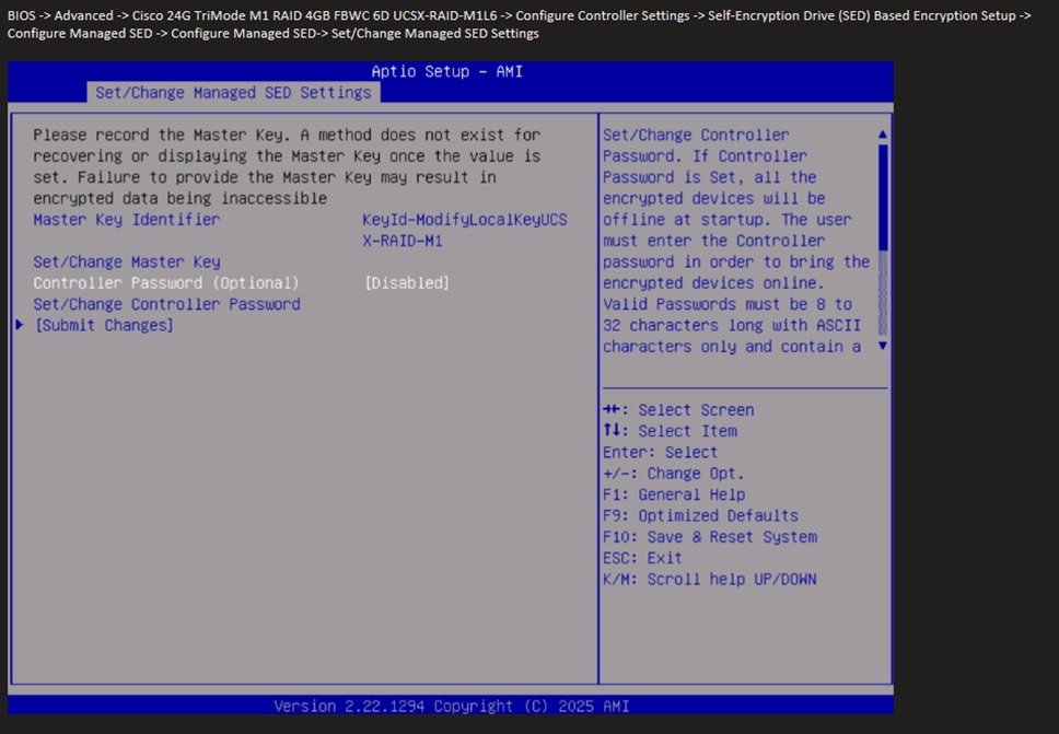
The BIOS screen for entering the tri-mode controller password.
The following table lists the tri-mode controller boot behavior given the various possible controller states.
Table 9. Drive controller boot and passphrase behavior for various conditions.
| Key Type |
Controller BIOS passphrase |
KMS available |
Boot behavior |
Notes |
| Local |
Disabled |
N/A |
Intervention not required. Legacy cached key behavior. |
Cached key boot |
| Local |
Enabled |
N/A |
Intervention required for SED access. Manual entry of controller passphrase required. |
Interrupted boot |
| Remote |
Disabled |
No |
Intervention not required. Legacy cached key behavior. |
Cached key boot |
| Remote |
Disabled |
Yes |
No intervention required. |
Normal boot |
| Remote |
Enabled |
No |
Intervention required for SED access. Manual entry of controller passphrase required. |
Interrupted boot |
| Remote |
Enabled |
Yes |
No intervention required. |
Normal boot |
SEDs with encrypted virtual disks (VDs)
If you build a secure RAID VD using storage policy, and the SEDs are in an unencrypted state, the secure VD will fail validation, saying that the drives are unencrypted. During validation, the following error will be displayed: “Existing drive group SED at end point is not secure, disable encryption for this drive group.” The SEDs must be in an encrypted state with a security flag of “unlocked” to create a secure VD.
To manage the encryption key for SEDs, you have a remote and a manual option. The remote key option is for environments that have deployed a Key Management Server (KMS) to handle the key generation and provisioning for the SEDs on the system. The server will communicate with the KMS and retrieve the SED key (KEK).
From the “Infrastructure Services” interface, select “Policies,” and then “Drive Security.”

Drive-security policy
Once in the policy wizard, click Start once you have named the policy. Select the Remote Key Management radio button.

Drive security Key Management selection: Remote or Manual.
Here you will enter your KMS information for your primary and secondary KMS server if one is available. You also have the option to change the secure communication port if you have set up your KMS with a custom value. Upload the root CA certificate from your KMS server and proceed to create the policy.
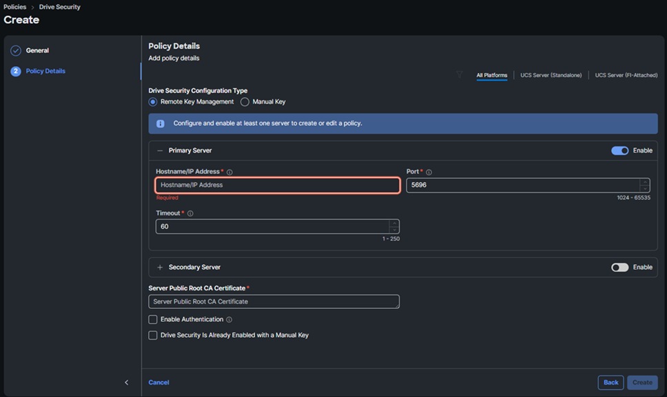
Enter Remote KMS information.
Click “Create” and complete the policy wizard.
A Manual Key policy uses a passphrase, supplied by the user, which is used to generate the Key Encryption Key (KEK). It is vitally important that you back up or otherwise store your passphrase in a safe location; for example, in a secured password manager. If the passphrase is lost it is unretrievable, and you will not be able to unlock or rekey your drives. The passphrase should contain at least 8 characters and at least one each of the following: upper case letter, lower case letter, number, and special character.
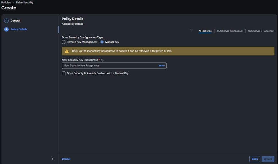
Enter Manual Key (local) passphrase for KEK generation
Once the passphrase is entered, click create to generate the policy.
Certificate management for the system itself, distinct from the drive-security policy discussed above, is used for secure management of the target from the device connector and Intersight Assist. In Intersight Managed Mode, the certificate- management policy allows you to specify the certificate and private key-pair details for an external certificate and attach the policy to servers. You can upload and use the same external certificate and private key-pair for multiple Intersight Managed Servers.
From the “Infrastructure Services” interface, select “Policies,” and then “Certificate Management.” You will need to create certificates and have the CA root certificate available to complete the process. We recommend that you work with your InfoSec team for this part of the deployment.
Begin by selecting the certificate you want to update or replace.
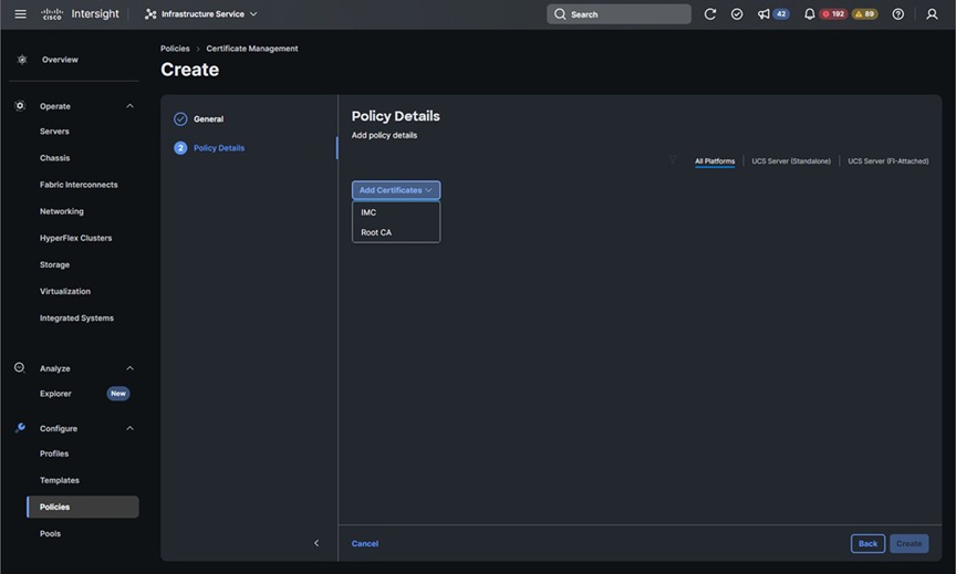
Select the certificate type to upload
Add the desired certificates.
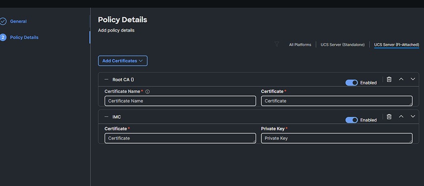
Upload the correct certificate and private key
Cisco Intersight provides a dashboard for real-time health and inventory status monitoring. You can create, customize, rename, and manage multiple dashboard views by adding, removing, or rearranging widgets. In the Widget Library, you can select the widget(s) that you want to pin to the dashboard, preview the details for a server or a cluster, search for a widget, and add a custom title to a widget. You can toggle between the detail and list view of the available widgets in the library. You can add multiple instances of a widget to monitor different targets. You can add a maximum of 30 widgets per dashboard.
Intersight Monitoring Services (IMS) provide historical and real-time visibility of resource consumption and inventory health, policies for notifications based on thresholds and anomaly detection, and actions and recommendations for automated infrastructure changes in response to events. IMS help reduce operational costs, prevent SLA violations, and increase system reliability and availability.
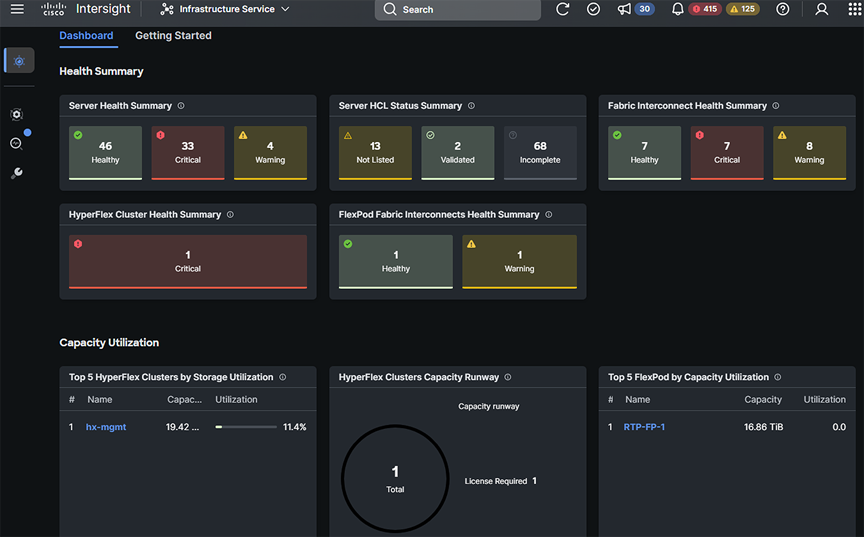
Intersight monitoring dashboard
Cisco Intersight Infrastructure Service (IIS)—built on the Cisco Intersight hybrid-cloud operations platform—is Cisco’s cloud-based infrastructure management solution delivered as a service. IIS is next-generation software that helps IT operations teams visualize, control, and automate compute, storage, and networking infrastructure—wherever it is—from one place.
● Visualize – Unlike traditional, siloed tools, Cisco Intersight gives you one consolidated dashboard to see your on-premises, cloud, and edge infrastructure—including their real-time status and interdependencies.
● Control – Whereas traditional infrastructure management typically requires multiple, repeated tasks, this platform lets you easily perform operations actions across your global infrastructure with just a few clicks so you stay in constant control. You can deploy, configure, and operate servers, VMs, storage, and networking throughout their lifecycle, from one place anytime, anywhere.
● Prevent and resolve – Improved capabilities to prevent and resolve issues stemming from computing hardware using advisories, hardware compatibility lists, proactive RMAs, firmware upgrades, and connected TAC are some of the biggest benefits operations teams get from Intersight.
● Automate – Instead of having to perform tasks manually, Intersight lets you automate day-0, day-1, and day-2 tasks and workflows to accelerate infrastructure operations.
Some of the key benefits of this platform include:
● Speed: deploy, configure, and maintain infrastructure in minutes—at scale—anytime, anywhere
● Consistency: ensure consistent server configuration across your global infrastructure to identify and eliminate configuration drift
● Security: apply strict security standards across infrastructure operations; continuously identify and mitigate potential security threats
● Audits and compliance: log all actions taken on your infrastructure; ensure consistent adherence to policies through automation, templates, and cross-domain management
● Control and manage: operate Cisco and third-party infrastructure from one place
● Reduce or eliminate downtime: address potential hardware, OS, and software issues before they impact users, or minimize them when they occur
● Improve productivity: reduce time spent on support, maintenance, and operation of multiple infrastructure domains, including networking, compute, storage, virtualization, and integrated systems
To set up syslog for your servers in Intersight, create a syslog policy. From the “Infrastructure Services” interface, select “Policies,” and then “Syslog.” Name the policy, then select “Next” to enter syslog details, including severity level and remote server information.

Syslog policy details
Select “Save” to complete the policy creation. Note that only the System Event Log (SEL) from the endpoint is covered in this policy. Transmission of endpoint SEL is not encrypted. For additional security, maintain the syslog server local to the endpoint, or enable an encrypted tunnel (IPsec, etc.) for the syslog server connection at your network border. For management audits, see the “Audit records, scope, and use cases” section below.
Audit records, scope, and use cases
Intersight maintains persistent records of every action taken within Intersight. These records are kept in the audit logs. These records include the create, update, and delete operations for every policy, pool, profile, role, etc. Essentially every managed object is tracked here. You will be able to see every management event that has taken place with the account on the devices claimed by the account.
Intersight Audit Records Entries
From the “System” interface, select “Audit Logs.” Alternatively, with Intersight’s command palette, press Ctrl+K (Windows/Linux) or Command+K (Mac) to pull up the search and type the word “audit,” as shown in Figure 55. Note that you can only view the audit log if you have an account administrator or audit log viewer role.
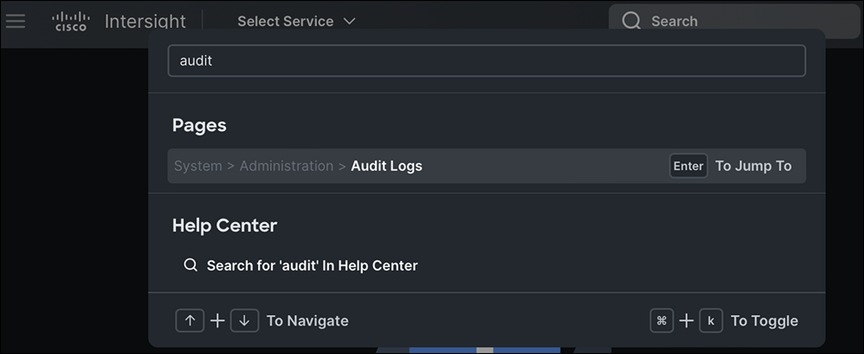
Command palette for getting to audit records
Here you will see a list of all events across the account, including the user that initiated the action, when it occurred, what the action was, and what entity was affected.
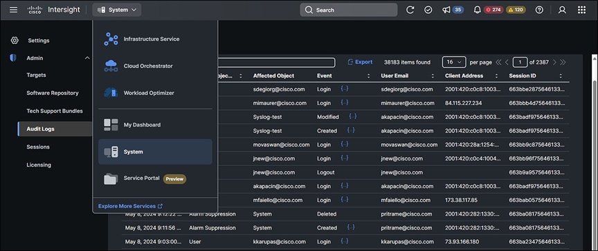
List of audit log events
You can drill down on the event by clicking the ellipses next to it. The figures below show a failed login attempt with the corresponding API JSON output followed by a successful login.
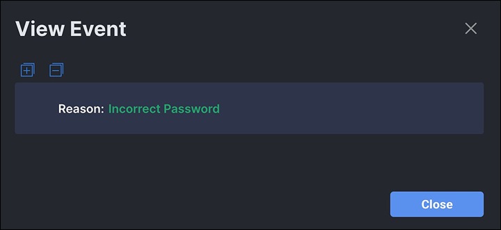
Failed login attempt
Audit JSON from API on failed login attempt:
{
“Account”: {
“ClassId”: “mo.MoRef”,
“Moid”: “627443cb7564612d30876271”,
“ObjectType”: “iam.Account”,
“link”: “https://sgaree-pva.ucstme.cisco.com/api/v1/iam/Accounts/627443cb7564612d30876271”
},
“AccountMoid”: “627443cb7564612d30876271”,
“AffectedObjectTypeLabel”: “”,
“Ancestors”: [],
“ClassId”: “aaa.AuditRecord”,
“CreateTime”: “2023-11-14T17:00:30.61Z”,
“DomainGroupMoid”: “627443cb7564612d30876272”,
“Email”: “admin@local”,
“Event”: “Failed Login”,
“InstId”: “6553a791756461301ff4c2c4”,
“MoDisplayNames”: {
“Name”: [
“admin@local”
]
},
« MoType »: « iam.User »,
« ModTime »: « 2023-11-14T17:00:30.724Z »,
“Moid”: “6553a7ae697265301f37ca7b”,
“ObjectMoid”: “62744b337564612d30879ddb”,
“ObjectType”: “aaa.AuditRecord”,
“Owners”: [
“627443cb7564612d30876271”
],
“PermissionResources”: [],
“Request”: {
“Reason”: “Incorrect Password”
},
“SessionId”: “”,
“Sessions”: null,
“SharedScope”: “”,
“SourceIp”: “”,
“Tags”: [],
“Timestamp”: “2023-11-14T17:00:01.787Z”,
“TraceId”: “NB7959e53b7f0bf7d557b568f6b910607b”,
“User”: {
“ClassId”: “mo.MoRef”,
“Moid”: “62744b337564612d30879ddb”,
“ObjectType”: “iam.User”,
“link”: “https://sgaree-pva.ucstme.cisco.com/api/v1/iam/Users/62744b337564612d30879ddb”
},
“UserIdOrEmail”: “admin@local”
},
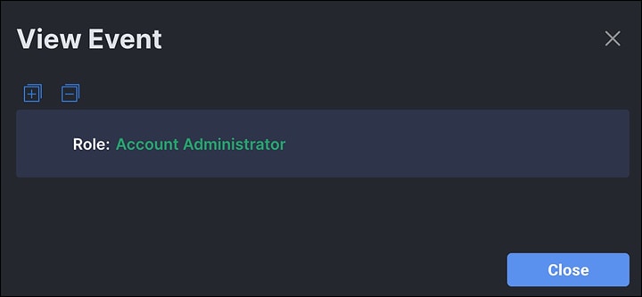
Successful administrator login
Audit JSON on successful login
{
“Account”: {
“ClassId”: “mo.MoRef”,
“Moid”: “627443cb7564612d30876271”,
“ObjectType”: “iam.Account”,
“link”: “https://sgaree-pva.ucstme.cisco.com/api/v1/iam/Accounts/627443cb7564612d30876271”
},
“AccountMoid”: “627443cb7564612d30876271”,
“AffectedObjectTypeLabel”: “”,
“Ancestors”: [],
“ClassId”: “aaa.AuditRecord”,
“CreateTime”: “2023-11-14T17:00:30.619Z”,
“DomainGroupMoid”: “627443cb7564612d30876272”,
“Email”: “admin@local”,
“Event”: “Login”,
“InstId”: “6553a798756461301ff4c2c8”,
“MoDisplayNames”: {
“Name”: [
“admin@local”
]
},
«MoType»: «iam.User»,
«ModTime»: «2023-11-14T17:00:30.724Z»,
“Moid”: “6553a7ae697265301f37ca81”,
“ObjectMoid”: “62744b337564612d30879ddb”,
“ObjectType”: “aaa.AuditRecord”,
“Owners”: [
“627443cb7564612d30876271”
],
“PermissionResources”: [],
“Request”: {
“Role”: “Account Administrator”
},
“SessionId”: “6553a798756461301ff4c2c7”,
“Sessions”: {
“ClassId”: “mo.MoRef”,
“Moid”: “6553a798756461301ff4c2c7”,
“ObjectType”: “iam.Session”,
“link”: “https://sgaree-pva.ucstme.cisco.com/api/v1/iam/Sessions/6553a798756461301ff4c2c7”
},
“SharedScope”: “”,
“SourceIp”: “10.99.97.86”,
“Tags”: [],
“Timestamp”: “2023-11-14T17:00:08.763Z”,
“TraceId”: “NBa8841f22dcf9933d0b69d8916b116696”,
“User”: {
“ClassId”: “mo.MoRef”,
“Moid”: “62744b337564612d30879ddb”,
“ObjectType”: “iam.User”,
“link”: “https://sgaree-pva.ucstme.cisco.com/api/v1/iam/Users/62744b337564612d30879ddb”
},
“UserIdOrEmail”: “admin@local”
},
Despite the audit logs containing tens of thousands of pages of records, it is still easy to isolate events to a specific user with a simple filter. Directly above the table is a magnifying glass with the words “Add Filter.” Clicking on the words “Add Filter” displays a drop-down list of attributes that can be used to filter the table. Multiple filters can be used.
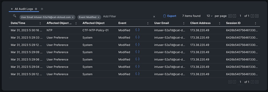
Audit entries
The table is sorted by most recent events, by default. You can drill down further by clicking the ellipses next to the event of interest.
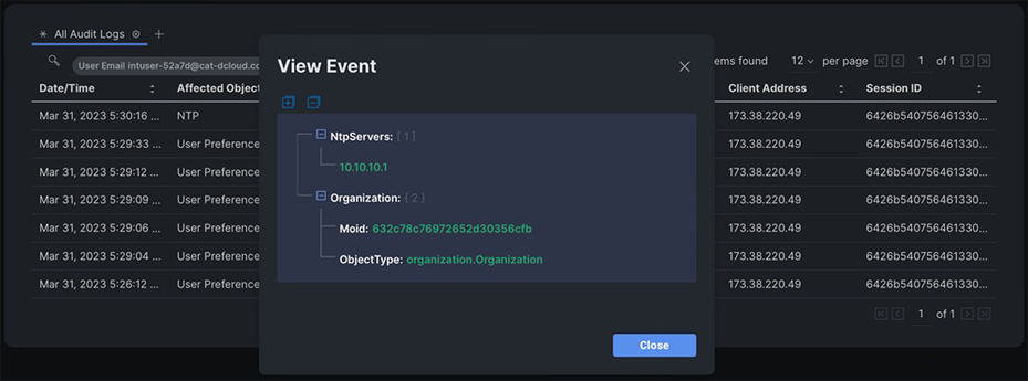
Audit entry details
Example use case: identify a record that has been changed
You can use the audit record to identify policy objects that have been modified. You can then use the API browser to perform a simple query for that managed-object ID (MOID). The API browser is a graphical tool for running API calls to Intersight without having to write any code. It is a tool for exploring and learning the API, but you can also use it for one-off API calls when you do not want to write any code.
To access the API browser:
1. Browse to intersight.com/apidocs/apiref
2. Use the search box to look for “audit”.
3. Click “aaa/AuditRecords”.
4. Click the first GET method.
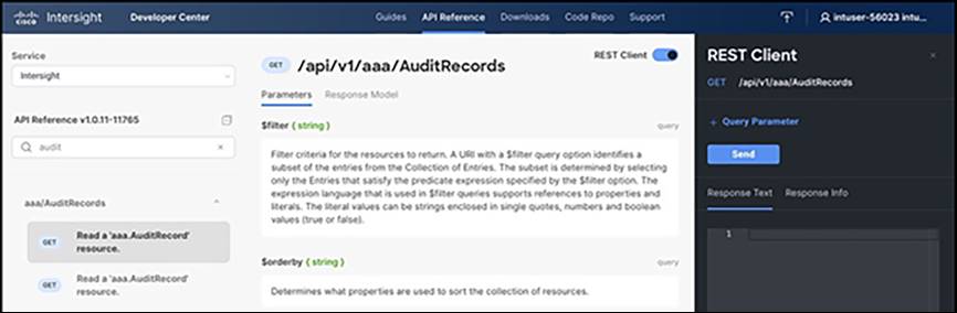
API browser
Apply a filter to reduce the number of records returned. The relevant query parameter called $filter. To add a query parameter, click the blue “+ Query Parameter” above the “Send” button. The key is $filter, and a sample MOID value is:
ObjectMoid eq ‘6425b04062757230016def13’
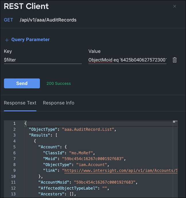
REST API query example using API explorer
Additional parameters can be added to the filter query to further reduce the results.
$filter = ObjectMoid eq ‘6425b04062757230016def13’ and Event eq Created
Intersight Virtual Appliance monitoring
The Intersight Virtual Appliance provides an overview of the appliance and health status and displays alarms when predefined limits are exceeded or when a threshold is raised.
In the appliance UI, from the “Service Selector” drop-down list, choose “System,” and navigate to “Settings > GENERAL > Appliance” to view the following details under “Appliance”:
● Health—the overall status of the appliance
● Hostname—your FQDN or hostname
● Version—the installed version of the appliance software
● Deployment size—the appliance deployment size. For detailed information about the deployment size, see Supported Configuration Limits for Intersight Virtual Appliance
● Node—a table view of the list of appliance nodes in the Cisco Intersight Virtual Appliance. You can search for a specific node by the IP address, operational status, gateway, or netmask. You can view the alarms in the right pane and filter them by their severity.
The Intersight Virtual Appliance monitors certain critical parameters and raises alarms when predefined limits are exceeded or when a threshold is raised. The appliance currently reports system-level and node-level alarms. The following table shows the alarm levels and their descriptions:
Table 10. Alarm levels for Intersight Appliance logging
| Level |
Component |
Description |
Comments |
| System |
Node |
A node is down. |
One alarm per node |
| System |
Node |
A node is not ready for service deployment. |
One alarm per node |
| Node |
CPU usage |
CPU usage above threshold |
One alarm per node. Threshold: 75% |
| Node |
Memory usage |
Memory usage above threshold |
One alarm per node. Threshold: 75% |
| Node |
File system disk usage |
File system disk usage above threshold |
One alarm per file system. Threshold: 75% |
| System |
Number of service instances running |
Number of service instances running less than expected |
One alarm for any service down |
| System |
Number of service instances ready |
Number of service instances ready less than expected |
One alarm for any service down |
| System |
Web certificate |
Warning: web certificate will expire within 120 days. Critical: web certificate will expire within 90 days. |
One alarm per appliance |
| System |
Device certificate |
Warning: device certificate will expire within120 days. Critical: device certificate will expire within 90 days. |
One alarm per appliance |
| System |
Appliance backup |
Warning: an Intersight appliance backup has not been created within the past week. Please schedule or create a new backup. |
One alarm per appliance |
| System |
Appliance backup |
Critical: the most recent Intersight Appliance backup failed. Please schedule or create another backup. |
One alarm per appliance |
| System |
Cloud connectivity |
Warning: connection to Intersight cloud has been down for more than 30 days. Critical: connection to Intersight cloud has been down for more than 60 days. Highly critical: connection to Intersight cloud has been down for more than 90 days; claiming new devices is not permitted until connection is restored. |
One alarm per appliance |
| Node |
Network link connectivity |
Warning: the latency between cluster nodes is greater than 10ms. |
One alarm per link per node |
Note: Cisco UCS C-Series server-related faults such as power-supply and fan failures are not forwarded by Intersight Virtual Appliance to an external syslog server. Please configure the external syslog server on the UCS C-Series CIMC side to handle the forwarding of the UCS C-Series events and faults.
Intersight and PVA/CVA syslog settings
Intersight Virtual Appliances offer external syslog configuration from System Settings. This syslog is for external retention of appliance logs, not for end-point logs. You can designate the web server access logs, audit logs, and alarms to be included in the log transport.
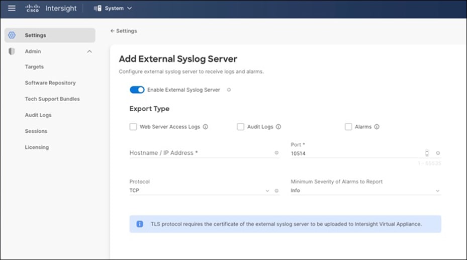
External syslog policy for Intersight Virtual Appliance
This guide has provided information and best practices for implementing Cisco UCS server ecosystems with Intersight. It is applicable to both on-premises implementations using the Private Virtual Appliance, the hybrid Connected Virtual Appliance, and the Cisco SaaS Intersight cloud service.
We looked at the chain of trust and how it relates to secure supply chain and manufacturing. This was followed by a comprehensive overview of certification and compliance on the Intersight platform. We looked at system and service privacy, communication, and connection methods. This was followed by the system-level security features of Cisco UCS in an Intersight deployment, which include secure system boot as well as policy-based deployments at scale. We covered monitoring, audit logs, decommissioning, and secure storage.
When we combine the inherent security features of the Cisco UCS platform, managed by Intersight, with common-sense security practices such as the following:
● Maintenance of physical security
● Keeping server OS and firmware patched and updated to mitigate new threats
● Disabling functions that are not required
● Maintaining application security with RBAC, patching, and firewalls, and
● Storing and delivering data securely with encryption in hardware both on the server and on the wire through ecosystem design we can ensure that our server environments are as secure as possible.
Note: Some of these links will require a Cisco account to log in.
Intersight general security information
● Cisco Trustworthy Technologies
Additional Intersight certification information
● ISO/IEC 27001:2013 certificate
● ISO/IEC 27017:2015 certificate
● Cisco Intersight SOC 3
Additional Intersight security guides
● Cisco Intersight Platform Privacy Data Map
● Cisco Intersight Platform Security Brief
Guidelines for secure policy settings
● IMM Security Policy Checklist and Intersight Help
Appendix A – Common security FAQ
How can I directly navigate to my identity provider for authentication?
You can bypass the Intersight main page during login by using a link containing the Intersight account and SSO ID, which will take you directly to your identity provider for authentication. The link should be structured to include the account ID, as well as the user ID being authenticated. An example of the link: https://5eb2e1e47564612d3079fe92.intersight.com/iam/weblogin?email=abc@domain.com.
How do I claim multiple targets at once in Intersight? Can I automate the bulk target claim process?
You can automate a bulk target claim using the Cisco Intersight API and Python SDK. For more information, see Automated Intersight Device Claim.
What happens to my data after I delete my account?
After account deletion, data is retained for a period of 90 days. You can place a request to purge the data upon termination of service. See the “Data deletion and retention” section in the Intersight Privacy Data Sheet.
Does Intersight use HTML5 on all pages? Does Intersight require any additional plug-ins?
Yes, Intersight uses HTML5 on all pages. Intersight does not require any additional plug-ins beyond your browser’s capabilities.
Does my application traffic flow into Intersight?
All application data and traffic remain on premises and control data (configuration, provisioning, and monitoring) is transmitted to Intersight.
Does Cisco have access to data running in my private cloud?
No, Cisco Intersight connects to the platform management interface, and the host/application data is not shared or accessed by Cisco Intersight.
Does Cisco Intersight support Single Sign-On (SSO) to integrate with my company’s directory services?
Yes, Intersight supports SSO through SAML 2.0 to enable you to integrate with your company’s directory services.
How often is the Intersight customer data backed up?
Customer data is encrypted using industry-standard AES-256 algorithm and backed up daily using automated scripts. Backups are replicated to a second region. Intersight retains the last 30 daily backups.
What is a resource group in Intersight?
A resource group is a logical container of resources available for a user account. An Intersight user classifies and manages resources through resource groups. The user can assign a resource group to one or multiple organizations.
What is an organization in Intersight?
An organization is a logical entity that supports multitenancy within an account through grouping of resources. An Intersight user can map the resource group to specific organizations and configure profiles and policies within the organization that can be applied to the targets.
What is a role? What is a system-defined role?
A role represents a collection of privileges to perform a set of operations and provides a user access to resources. A system-defined role is created by default in an account. Each system-defined role has a unique privilege, such as a device-administrator or service-administrator privilege, associated with it. These roles cannot be edited by users, and they apply to an entire account. The system-defined roles in Intersight are account administrator, read-only, HyperFlex cluster administrator, server administrator, user access administrator, device administrator, and device technician.
What is a user-defined role? Why do I need a user-defined role?
User-defined roles are introduced to grant multiple privileges to a role, and to expand the scope of a privilege to an entire account or to an organization. For example, “Role-All” could include a combination of server-administrator and device-administrator privileges applicable account-wide. “Role-Org - ‘Org1’” could include a combination of server- administrator and read-only privileges, and “Role-Org - ‘Org2’” could include a combination of HyperFlex cluster-administrator and server-administrator privileges, applicable organization-wide.
What is a privilege?
A privilege is a set of actions grouped by functionality, such as server administrator, read-only, device technician, etc. A role can have a unique or multiple privileges associated with it.
What is single sign-on?
Single Sign-On (SSO) authentication enables you to use a single set of credentials to log into multiple applications. With SSO, you can sign into Cisco Intersight with your corporate credentials instead of your Cisco ID.
How does Intersight enable SSO?
Cisco Intersight supports SSO through SAML 2.0 and acts as a Service Provider (SP) to enable integration with IdPs for SSO authentication. You can configure your account to use the Cisco ID and SSO to sign into Intersight. To integrate your IdP with Intersight, you must have an Intersight account. If you do not have an Intersight account, you can set up one on intersight.com.
Why am I seeing two different options to log into Intersight?
Intersight now provides two options to sign in. Select Cisco ID, or your corporate ID that you have registered with your IdP if you want to sign in with SSO. You can sign into your account from https://intersight.com/ or log in directly with your account URL, which is https://account_id.intersight.com.
What is multifactor authentication?
Multifactor authentication is the process of using a factor to identify users in addition to the password or another known factor. Multifactor authentication provides an extra layer of security to protect your account and reduces the risk of unauthorized access to your sensitive data.
When will I be required to set up multifactor authentication?
You will be required to set it up for your new or existing Intersight account after you enable the requirement for multifactor authentication in Intersight.
Is the verification code mandatory?
Yes, the verification code is mandatory when you enable multifactor authentication, regardless of where you enable it – from Intersight or from the Cisco ID profile management portal.
How can I generate a verification code?
You can install a desktop/mobile app or choose to get the verification code sent to your email. Follow the instructions provided in the Cisco ID profile management portal to complete the setup of the authentication application before you generate the verification code.
How is the device connector upgraded?
Device connectors are upgraded automatically without any impact on other software components. They are upgraded in the following cases:
● When a supported system (Cisco UCS Manager, Cisco HyperFlex) is upgraded, except when the device connector is already at a recent version
● When security patches are required
● When a new functionality introduced in Intersight requires a device connector upgrade
What information does the device connector collect?
Device connectors collect the following information:
● Inventory data for all components including storage controllers, network adapters, IO modules, fabric interconnects, and CPUs for Cisco UCS and HyperFlex Systems
● Inventory, and server operational data, such as faults to provide automated recommendations
● Tech-support files when requested by Cisco Technical Assistance Center (Cisco TAC)
Note: Device connectors do not collect sensitive data such as passwords configured in the supported systems.
Who has access to information collected by Intersight?
The Cisco Intersight-supported team, a limited group of Cisco engineers and support staff, have access to information collected by Intersight. See the “Access control” section in the Intersight Privacy Data Sheet.
Does IS/PVA/CVA verify images being loaded into the software repository with a digital signature like an x509 certificate or a hash?
The software repository treats is just a file repository with only loose coupling to file types. Integrity is checked on consumption. Firmware files have a defined structure. Not only signature and integrity checks are performed, but also suitability checks. You can’t install B200M6 firmware on a X210cM7 server, even though the file contents are very similar.
Appendix B – PVA/CVA licensing data details
What does the licensing string required for the PVA installation contain? Is it a completely random string, or does it contain obscured information? The figure below shows a sample of this license.
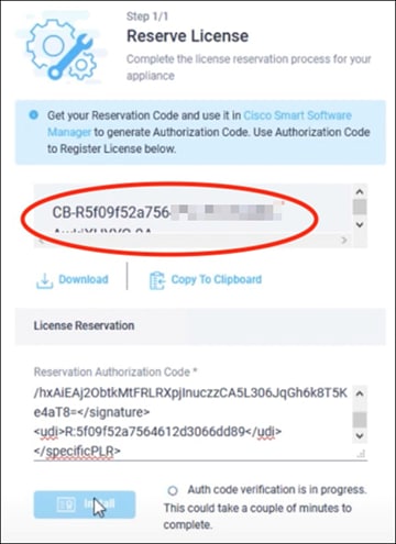
PVA license codes
This is a base58 encoding (chosen over base64 to eliminate some problematic characters for human transcription, such as zero and capital “O”) for the UDI. These licenses are securely transmitted using AES256 and contain the following:
Code content: <version><sequence>-<UDI>-<SW id tag>-<hash>
The hash in this case is the last two characters of the MD5 of the IDs. The UDI is a new device identifier generated during the process that consists of the PID, serial number, and UUID.
The information that is used to generate the reservation code is the account ID, which is the product ID for licensing.
The request code contains:
● UDI of the device
● Software ID of the device
The software ID is displayed on “show license tech support” and is common for all instances of the same version. The UDI is unique to your instance. But having a UDI itself will not be able to provide any access. The UDI information is also common information that is sent to and received by Cisco.
Other than this, there is no information related to the customer or customer account in the request code.
The reservation workflow is not communicated over the internet. You need to log into your appliance and paste the request code to select what type of license to reserve.
AIK – Attestation Identity Key. The Trusted Platform Module (TPM) can be used to create cryptographic public/private key pairs in such a way that the private key can never be revealed or used outside the TPM (that is, the key is non-migratable). An AIK can be used to guarantee that a certain cryptographic operation occurred in the TPM of a particular computer because any operation that uses the private key of such a key pair must have occurred inside that specific TPM.
An AIK can also be useful to prove cryptographically that a private key has this property and that any use of it must have occurred inside that TPM.
An attestation identity key is used to provide such cryptographic proof by signing the properties of the non-migratable key and providing the properties and signature to the CA for verification. Since the signature is created using the AIK private key, which can only be used in the TPM that created it, the CA can trust that the attested key is truly non-migratable and cannot be used outside that TPM.
CA – Certificate Authority, a trusted certificate signature provider
CC – Common Criteria is an international standard for computer security certification. It has various evaluation levels called EALs. Most organizations typically certify to EAL 2.
Cisco SKS – Cisco Session Key Services, basically proprietary SKIP
CNSA – Commercial National Security Algorithm (or Suite) is a set of cryptographic algorithms promoted by the National Security Agency as a replacement for NSA Suite B Cryptography algorithms.
CSfC - Commercial Solution for Classified certifications
DH – Diffie-Hellman key-exchange algorithm
EAP-TLS - Extensible Authentication Protocol–Transport Layer Security (EAP-TLS) is an IETF open standard defined in RFC 5216. More colloquially, EAP-TLS is the authentication protocol most commonly deployed on WPA2-Enterprise networks to enable the use of X.509 digital certificates for authentication.
EAP-TLS is considered the gold standard for network authentication security, but despite being universally recognized as ultra-secure, it’s still not widely implemented.
ECC - Elliptic-curve cryptography is an approach to public-key cryptography based on the algebraic structure of elliptic curves.
ECDH - Elliptic-Curve Diffie–Hellman is a key-agreement protocol that allows two parties, each having an elliptic-curve public–private key pair, to establish a shared secret over an insecure channel.
HSS – Hierarchical signature system
IETF - Internet Engineering Task Force, founded in 1986, is the premier Standards Development Organization (SDO) for the internet.
IKE - IKE (Internet Key Exchange) is a protocol used in IPsec (internet protocol security) for ensuring secure, authenticated key exchange and establishing Security Associations (SAs). IKE plays a crucial role in setting up the cryptographic parameters for securing IP communications.
IKE automates the process of generating, exchanging, and managing cryptographic keys required for IPsec, and also negotiates the IPsec Security Associations (SAs) parameters.
Kyber – Kyber is a Key-Encapsulation Mechanism (KEM) designed to be resistant to quantum decryption attacks. It is used to establish a shared secret between two communicating parties without an attacker in the transmission system being able to decrypt it. This is an asymmetric cryptosystem.
LDWM (Lamport, Diffie, Winternitz, and Merkle) – a special hashing scheme developed for signatures that is considered to be quantum resistant
LMS - Leighton-Micali signature, a stateful hash-based algorithm and its multi-tree variants used for HSS
MACsec – MAC address security. MACsec typically relies on PPK
NDcPP - Network device collaborative protection profile
OTN SEC – Optical transport network security
QKD - Quantum key distribution is a secure communication method that implements a cryptographic protocol involving components of quantum mechanics. It enables two parties to produce a shared random secret key known only to them, which then can be used to encrypt and decrypt messages. The process of quantum key distribution is not to be confused with quantum cryptography, but it is the best-known example of a quantum-cryptographic task.
PPK – Pre-placed key (symmetric encryption key, prepositioned in a cryptographic unit)
PQC – Post-quantum cryptography
SHA – Secure hash algorithm
Shim – A shim is a pre-bootloader that runs on UEFI systems and is meant to be a bit of code, signed by Microsoft, that embeds Cisco’s certificate (which signs Cisco’s GRUB binaries) so that the system can load the “real” bootloader: GRUB.
SKIP - SKIP (Simple Key-Management for Internet Protocol) is a protocol for sharing encryption keys1. It generates platform-independent encryption keys for specific sender-receiver pairs2. The SKIP cipher is a transposition cipher that reorders letters in a message3. In SKIP, the master key is hashed to produce the key used for IP packet-based encryption and authentication.
SUDI - Secure Unique Device Identifier is an IEEE 802.1AR-compliant secure device identity in an X.509v3 certificate that maintains the product identifier and serial number. The SUDI can be used for asymmetric key operations such as encryption, decryption, signing, and verifying that allow passage of the data to be operated upon.
TPM – Trusted Platform Module. An immutable hardware key store.
XMSS - eXtended Merkle Signature Scheme, a stateful hash-based algorithm and its multi-tree variants used for HSS.
Appendix D – USB OS install boot procedure
Media requirements
Because UEFI is more restrictive than legacy BIOS, there are specific requirements for your USB drive and BIOS settings to ensure that the drive is recognized. In a hardened posture, the USB ports should be disabled. This procedure shows you how to enable them for OS installation. Be sure to disable them again once OS installation is complete Note that you may need to add Cisco drivers downloaded from CCO to the boot image to complete the OS installation (for example, mass storage drivers).
USB drive requirements for UEFI
For the BIOS to “see” the USB drive as a UEFI bootable device:
● File system: The USB drive must be formatted as FAT32. UEFI firmware typically cannot read NTFS or exFAT partitions for booting.
● Partition scheme: It is recommended to use GPT (GUID Partition Table) rather than MBR.
● Boot files: The drive must contain the \EFI\BOOT\BOOTX64.EFI file (this is standard for most modern OS installers such as Windows Server, RHEL, or VMware).
USB enablement requirement
1. Enabling physical USB ports (BIOS)
a. If the USB ports were disabled for security reasons, you must re-enable them in the BIOS.
2. Restart the server and press F2 when the Cisco logo appears to enter the BIOS Setup.
3. Navigate to the Advanced tab.
4. Select USB Configuration.
5. Ensure USB Stack is set to [Enabled].
6. Check USB Port Configuration to ensure individual ports (Front, Rear, Internal) are set to [Enabled].
7. Press F10 to save and exit.
Important Note: Smart Access USB must be set to “Host” mode.
On M7 servers, the front-panel USB port can be toggled between the Host OS and the BMC (CIMC).
If your USB drive is not detected by the BIOS, ensure that Smart Access USB is set to “Host” mode in the CIMC settings or BIOS. You can check this in CIMC under Compute > BIOS > Advanced > USB Configuration.
Procedure requirements
To boot from a USB drive for OS installation on a Cisco UCS C220 M7 Rack Server, you can use either a physical USB drive or the “Virtual Media” feature through the Cisco Integrated Management Controller (CIMC).
Method 1: Using a physical USB drive (one-time boot)
This is the fastest method if you have a physical bootable USB drive plugged into the server.
1. Insert the USB drive into one of the USB ports (front or rear).
2. Power on or restart the server.
3. Watch the screen during the POST (power-on self-test) process. When the Cisco splash screen appears, press F6 to enter the Boot Menu.
4. A list of bootable devices will appear. Select your USB drive (it may appear as “USB Device,” “Generic Flash Disk,” or by the manufacturer’s name).
5. Press Enter to begin the installation.
Method 2: Using CIMC Virtual Media (recommended)
This method allows you to “mount” an ISO file from your laptop or workstation as if it were a physical USB/DVD drive.
1. Log in to the CIMC Web UI using the server’s management IP.
2. Launch the KVM Console (click the “Launch KVM” button).
3. In the KVM window, click the Virtual Media tab and select Activate Virtual Devices.
4. Click Map CD/DVD (or Map Removable Disk) and browse to select your OS ISO file.
5. Once mapped, restart the server from the KVM (Power > Reset System).
6. Press F6 during boot and select Cisco Virtual CD/DVD to boot from the ISO.
Method 3: Changing the permanent boot order (BIOS)
If you want the server to always check the USB port first:
1. Press F2 during boot to enter the BIOS Setup.
2. Navigate to the Boot Options tab.
3. Select Configure Boot Order.
4. Move USB Device or Virtual Media to the top of the list.
5. Press F10 to save and exit.
Appendix E – Trust Anchor and Trusted Platform Module
Below is a clear, side-by-side comparison of Trust Anchors vs. Trusted Platform Modules (TPMs), what each one does, and how they work together in secure boot, including OS verification. The trust anchor enforces what is allowed to run, while the TPM measures what actually ran and protects secrets based on that measured state. Together they form a complete secure boot and OS verification system.
1. High-level comparison
| Aspect |
Trust Anchor |
TPM (Trusted Platform Module) |
| What it is |
A root of trust (keys + immutable code) |
A secure cryptographic processor |
| Primary role |
Decides what is allowed to run |
Records, protects, and enforces trust decisions |
| Executes code? |
Yes (initial verification code) |
No (policy + crypto only) |
| Can block boot? |
Yes (secure boot enforcement) |
Indirectly, yes (by withholding secrets) |
| Stores secrets |
Yes (usually public keys) |
Yes (private keys, sealed data) |
| Measures boot state |
No (by itself) |
Yes (PCRs) |
| Performs attestation |
No |
Yes |
| Required for secure boot |
Yes |
No (but strongly recommended) |
2. Trust Anchor: what it does
Definition
A trust anchor is the starting point of trust: something the system assumes is correct and secure.
What it contains
● Immutable verification code (ROM or protected flash)
● One or more public keys
● Policy for verifying firmware
Core responsibilities
● Verifies the next stage before executing it
● Enforces secure boot (allows or denies execution)
● Anchors firmware updates to signed images
Example Trust Anchors
● CPU ROM (hardware root of trust)
● OEM public key embedded in UEFI
● Platform security controller
3. Trusted Platform Module (TPM): what it does
Definition
A TPM is a tamper-resistant cryptographic engine that:
● Measures system state
● Protects secrets
● Enforces security policy based on measurements
Core responsibilities
TPM does not decide what runs—it only reacts to what ran.
● Measures each boot stage (hashing)
● Stores measurements in Platform Configuration Registers (PCRs)
● Seals/unseals secrets based on system state
● Perform sattestation (prove system integrity)
4. How they work together during secure boot
Boot flow with both present
[Trust Anchor]
↓ verifies
Firmware
↓ verifies
Bootloader
↓ verifies
OS kernel
Meanwhile:
[TPM]
← measures each step
← records hashes in PCRs
5. Secure boot enforcement (Trust Anchor)
The trust anchor enforces secure boot (this is a prevention mechanism):
● Each stage is digitally signed.
● Signature is verified using trust anchor keys.
● If verification fails:
◦ Execution is blocked
◦ Recovery mode is entered
Example:
● UEFI verifies bootloader.
● Bootloader verifies OS kernel.
6. Measured boot and policy enforcement (TPM)
The TPM measures what actually ran (this is a detection + consequence mechanism):
● Each stage’s hash is extended into PCRs.
● PCR values represent the full boot history.
The TPM then:
● Releases secrets only if PCRs match expected values
● Refuses if firmware or OS was modified
7. Operating system verification
Trust Anchor side (verification)
● UEFI verifies:
◦ Bootloader signature
◦ Kernel signature
● Ensures only approved OS code runs
TPM side (measurement and sealing)
● OS boot components are measured,
● Disk encryption keys (for example, BitLocker/LUKS) are sealed to PCRs.
● If OS changes unexpectedly:
◦ TPM will not release keys.
◦ OS cannot access encrypted storage.
8. Why both are needed
Trust Anchor alone
● Prevents unsigned code
◦ Cannot prove system state later
◦ Provides no protection for secrets after boot
TPM alone
● Records system state
◦ Cannot stop malicious code from executing
Together, Trust Anchor and TPM
● Prevent execution of unauthorized code
● Detect tampering
● Protect secrets
● Enable remote attestation
9. Common misconception
“TPM provides secure boot.”
● Secure boot is enforced by the trust anchor.
● TPM supports secure boot with measurement and policy.
Appendix F – Microchip Adaptec Tri-Mode Disk Controller
Microchip Adaptec Tri-Mode Disk Controllers are enterprise storage controller cards (HBAs or RAID adapters) made by Microchip Technology under the Adaptec name using Knox-based technologies. Their defining feature is “tri-mode” connectivity, meaning a single controller can manage three different storage interface types simultaneously:
● SAS (Serial attached SCSI)
● SATA (Serial ATA)
● NVMe (PCIe-based storage)
Traditional controllers supported either:
● SAS/SATA or
● NVMe (PCIe)
Tri-mode controllers unify them by using:
● PCIe lanes for NVMe drives
● SAS protocol for SAS/SATA drives
● A shared physical backplane that can route either protocol
Result: You can plug different drive types into the same system without changing controllers.
Microchip tri-mode (Knox-based) controllers and local/remote key behavior for self-encrypting drives (SED)
Note: If you decide not to cache the SED key on the controller to protect from wandering servers, then any power cycle will be BIOS-interrupted and require a password to access the disks attached to the controller.
Q :Since Knox controllers don’t cache the key encryption key (KEK) by default, if we are in local key (manual key with passphrase) mode, do we need to enter the passphrase on reboot?
A: In LKMS, if the controller password is set, users MUST provide the controller password on reboot in order to let the firmware decrypt the encrypted master key saved in NVRAM to unlock the drive(s).
Q: In local key mode with IMM, is the KEK stored anywhere in Intersight or just generated as needed with the passphrase?
A: KEKs are generated as needed by the controller firmware.
From the Microchip controller documentation:
8.3.4.4 Unlocking Controller
When Controller Password is set in local key management mode, data on the encrypted devices will be offline during system boot. The controller password must be entered to unlock the controller and bring the encrypted devices online. After three wrong attempts, the controller password will be locked out for some time. If controller password is set along with remote key management mode and on any of the subsequent reboot if controller detects that the key management server is unavailable, then unlock option is provided in the UEFI HII menu. Controller can only unlock encrypted devices if the key management server is made available or a valid controller password is entered.
1. Boot to system BIOS setup utility and select the controller to enter the HII configuration utility.
2. From the main menu, select Configure Controller Settings > Self-Encryption Drive (SED) Based Encryption Setup.
3. Select Unlock Controller.
4. Enter controller password, then select Submit.
Note: In local key management mode, it is recommended to supply the password, before performing any operations such as removing or adding the drives. Without the password, the controller will not be able to unlock the drive to perform the RAID operations such as rebuild, background parity initialization, and consistency check operations.
7.2.4.4 SED Keys Management Overview
MCHP controllers do not cache the SED Key (KEK). Instead, the KEK (essentially the SED unlock PIN) is derived by hashing a Master Key, which is:
● Provided by the user in Local KMS (LKMS) mode.
● Provided by a KMS server in External KMS (EKMS) mode.
This KEK is used to unlock each drive’s Media Encryption Key (MEK).
● LKMS:
◦ Controller password disabled
◦ Master key is stored in NVRAM as plain text. Master key hashed->generate SED key every time.
◦ Master Key is encrypted and stored in NVRAM. Master key decrypted->hashed->Generate SED key every time when needed.
◦ Controller password enabled.
● Controller password is used to encrypt the master key and stored in NVRAM. Master key decrypted->hashed->Generate SED key every time when needed.
● EKMS:
◦ Controller password disabled
◦ Controller gets Master key from KMS server through EFI KMS protocol. Master key hashed -> generate SED key every time. No KMS communication. SED drives remain data locked.
◦ Controller password enabled (controller firmware encrypt the master key from KMS server and stores in NVRAM).
◦ As long as the KMS connection is successful, same as above.
◦ If KMS connection is failing, this is where the controller password option is used as a back-up option for user to access data.
◦ The encrypted master key stored in controller NVRAM will be used to unlock all the SEDs as long as user provide controller password during POST.
RMA scenarios:
Case 1: Server replacement
● Drives and original controller moved to new server with same configuration.
● Controller boots, detects MCHP-owned SEDs, and unlocks automatically.
● If controller password was enabled, it must be entered.
Case 2: Controller replacement
● New controller detects MCHP SEDs, but:
◦ Without encryption: Drives remain locked unless user imports.
◦ With encryption (Master Key B on new controller):
● Volume import prompts user for original Master Key A to unlock SEDs.