EDFA2 line card
The new EDFA2 line card is an optical amplifier that serves as an essential component of the line system solution. It functions as a DWDM optical terminal and includes a C-band bidirectional amplifier with channel power control capabilities
This card enhances optical signal amplification along with the integration support for the Optical Supervisory Channel (OSC), Optical Time Domain Reflectometer (OTDR), and QDD Coherent Probe pluggables.
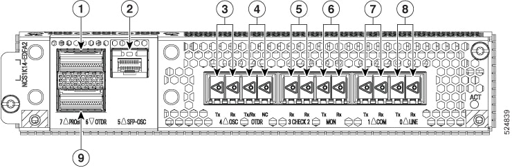
This image shows the EDFA2 optical amplifier line card.
|
Callout |
Connector label |
Connector type |
Port name |
|---|---|---|---|
|
1 |
PROBE |
LC |
Coherent probe 7 |
|
2 |
SFP-OSC |
LC |
OSC port 5 |
|
3 |
OSC |
LC |
OSC TX 4 |
|
OSC RX 4 |
|||
|
4 |
OTDR |
LC |
OTDR TX/RX |
|
OTDR NC |
|||
|
5 |
CHECK |
LC |
CHECK RX 2 |
|
CHECK RX 3 |
|||
|
6 |
MON |
LC |
MON TX |
|
MON RX |
|||
|
7 |
COM |
LC |
COM TX 1 |
|
COM RX 1 |
|||
|
8 |
LINE |
LC |
LINE TX 0 |
|
LINE RX 0 |
|||
|
9 |
OTDR |
LC |
OTDR port 6 |
|
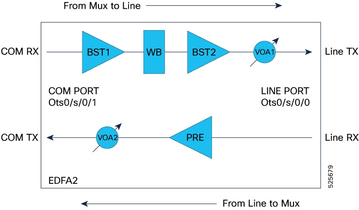
Monodirectional transmitter section |
Monodirectional receiver section |
|---|---|
|
Path: From COM-RX port to LINE-TX port |
Path: From LINE-RX port to COM-TX port |
|
Components:
|
Components:
|
EDFA2 line card features
These are EDFA2 line card features:
-
The card comprises an optical module, pluggable cages for OTDR and OSC, and a DWDM trunk interface. It features integrated management for alarms, performance monitoring, and optical power level control.
-
The EDFA2 card consumes a maximum power of 60W excluding any optics.
-
The EDFA2 card consumes a maximum power of 82W including OSC, OTDR, and Coherent probe.
-
NCS1014 chassis with Single EDFA2 card and FAN-P module consumes a maximum power of 360W including OSC, OTDR, and Coherent probe.
-
For Release 25.1.1, only single-span point-to-point configurations are supported. This setup requires two nodes, each equipped with an EDFA2 card, with the span connected to their respective Line ports.
Supported modules and optical channel
The EDFA2 line card supports these modules and channel:
-
ONS-QSFP-OTDR — ONS OTDR pluggable module
-
DP01QSDD-ZT5-A1 — QDD coherent probe pluggable module
-
ONS-SC-PTP-1510 — SFP Optical Supervisory Channel
EDFA2 controllers
|
Feature Name |
Release Information |
Feature Description |
|---|---|---|
|
NCS1K14-EDFA2 Port configurations |
Cisco IOS XR Release 25.1.1 |
The NCS1K14-EDFA2 line card is an optical amplifier card that offers OTDR, coherent probe, and OSC support to NCS 1014 networks. This card has an OTDR QDD port for initiating OTDR scan and bidirectional OTDR LC ports to test the fiber health. The probe QDD port enables optical line verification towards the NCS1K-MD-32X-CE patch panel. This card supports different datapath controllers such as:
This card provides up to 796 slices at 6.25GHz spacing. The card has an internal Wave Blocker that can attenuate the optical power of provisioned channels slice by slice at 6.25 GHz. You can set up this EDFA card in flex grid mode to adapt signal amplification on each channel. |
There are four types of controllers for EDFA2 card. The controllers are the OTS, OTS-OCH, OSC, and Optics controllers.
|
Controller types |
Description |
|---|---|
|
Optical Transport Section (OTS) |
The OTS controller holds all the optical parameters for the OTS optical interfaces. |
|
OTS-OCH |
The OTS-OCH controller is created on the channel of the EDFA2 card using the |
|
Optical Service Channel (OSC) |
The OSC controller represents the optical layer of the OSC channel. Line ports host the OSC controller. |
|
GiabitEthernet for OSC |
The OSC controller represents SFP pluggable for Optical Supervisory Channel/Gigabit Ethernet Interface. |
|
OTDR |
The OTS controller is a function or component within a system that manages the operation of an OTDR device. |
|
Optics |
The Optics controller represents Coherent Probe and SFP pluggable for Optical Supervisory Channel/Gigabit Ethernet Interface. |
|
CoherentDSP |
The Optics controller represents the QSFP DD for Coherent Probe. |
EDFA2 controllers parameters
Controllers holds all the optical parameters for the optical interfaces. The optical interface has different capabilities depending on its hardware components such as photodiode, VOA, amplifier, and OCM.
OTS controller:
The OTS controller is created by default when you bring up the EDFA2 line card. In the EDFA2 line card, the OTS controller is supported on the LINE and COM optical ports. OTS controllers associated to LINE and COM optical ports will be in the form of:
-
LINE: controller Ots 0/<slot-id>/0/0 where slot-id is 0…3
-
COM: controller Ots 0/<slot-id>/0/1 where slot-id is 0…3
-
CHECK:
-
controller Ots 0/<slot-id>/0/2 where slot-id is 0…3
-
controller Ots 0/<slot-id>/0/3 where slot-id is 0…3
-
OSC controller:
The EDFA2 card includes Optical Service Channel (OSC) ports, which enable the creation of a bidirectional communication channel to connect two nodes in a DWDM network.
-
controller Osc 0/<slot-id>/0/0 where slot-id is 0…3 (this represents the OSC channel towards LINE-TX)
-
controller Osc 0/<slot-id>/0/4 where slot-id is 0…3 (this represents the OSC physical port towards the OSC pluggable)
Optics:
-
controller optics 0/<slot-id>/0/5 where slot-id is 0…3
-
controller optics 0/<slot-id>/0/7 where slot-id is 0…3
The tables list the OTS controller parameters.
| Parameter | Description | Applicable modules | Value | Default |
|---|---|---|---|---|
| egress-ampli-mode | amplifier mode | amplifier | gain mode | gain mode |
| egress-ampli-gain-range | amplifier gain range | amplifier | normal and extended:
on ots 0/<slot-id>/0/0 only normal is supported |
normal |
| egress-ampli-gain | amplifier gain set point | amplifier |
ots 0/<slot-id>/0/0 from 12 to 27 dB ots 0/<slot-id>/0/1 from 0 to 28 dB in normal ots 0/<slot-id>/0/1 from 20 to 39 dB in extended |
on ots 0/x/0/0 default gain is 17 dB on ots 0/x/0/1 default gain is 5 dB |
| egress-ampli-tilt | amplifier tilt set point | amplifier | -5 to 5 dB | 0 dB |
| egress-ampli-safety-control-mode | amplifier safety mode configuration | amplifier | auto and disabled | auto |
| egress-ampli-osri | amplifier optical safety remote interlock | amplifier | on and off | off |
| egress-ampli-force-apr | amplifier automatic power reduction configuration | amplifier | on and off | off |
| egress-ampli-br-high-threshold | amplifier threshold value for detection of high reflected power at the LINE TX port. | amplifier | -50 to 0 dB | -17 dB |
| tx-voa-attenuation | TX VOA attenuation set point | VOA |
ots 0/<slot-id>/0/0 from 0 to 20 dB ots 0/<slot-id>/0/1 form 0 to 15 dB |
0 dB |
| rx-low-threshold | threshold value for detection of power loss at the LINE and COM RX ports. | photodiode |
ots 0/<slot-id>/0/0 -47 to 21 dBm ots 0/<slot-id>/0/1 -30 to 25 dBm |
ots 0/x/0/0 -47 dBm ots 0/x/0/1 -30 dBm |
| tx-low-threshold | Threshold value for detection of power loss at the LINE and COM TX ports. | photodiode | ots 0/<slot-id>/0/0 -22 to 25 dBm
ots 0/<slot-id>x/0/1 -20 to 25 dBm |
-7 dBm |
| Parameter | Description | Applicable modules | Value | Default |
|---|---|---|---|---|
| egress-channel-slice | channel slice attenuation set point | wavelength blocker |
0 to 15 dB attenuating signal 15.1 to 25 dB blocking signal |
25 dB |
| egress-ampli-br-high-threshold | amplifier threshold value for detection of high reflected power at the LINE TX port. | amplifier | -50 to 0 dB | -17 dB |
| Parameter | Description | Applicable modules | Value | Default |
|---|---|---|---|---|
| ingress-ampli-gain-range | amplifier gain range | amplifier | normal and extended | normal |
| ingress-ampli-gain | amplifier gain set point | amplifier |
normal 5 to 11 dB extended 17 to 23 dB |
normal 5 extended 17 |
| ingress-ampli-osri | enable or disable OSRI at the LINE and COM ports | amplifier |
on and off |
off |
| Parameter | Description | Applicable modules | Value | Default |
|---|---|---|---|---|
| rx-low-threshold | threshold value for detection of power loss at the CHECK 2 and 3 ports. | photodiode | -40 to 10 dBm | -37 dBm |
| Parameter | Description | Applicable modules | Value |
|---|---|---|---|
| OTS controller Shutdown (LINE/COM Port) | turn off all the amplifiers on that port | amplifier | shutdown and no shutdown |
OTS-OCH controller
OCH controllers associated to different Optical Channels are configured with the command.
controller Ots-Och 0/<slot-id>/0/<port-id>/<ch-id>
| Parameter | Description |
|---|---|
|
Ots-Och controller Shutdown (OCHs) |
Wavelength Blocker will be set to Not Active for the Ots-Och specific slices in the LINE TX direction, to block the channel transmission |
Configure the EDFA2 line cards
You can configure the EDFA2 grid mode, define channel properties, and manually set gain and attenuation parameters for various amplifier stages to achieve desired optical power levels.
The EDFA2 configuration comprises three distinct stages, each performing specific amplification and control functions:
-
Stage 1: Ingress (COM RX Port) This stage includes the EDFA2 Booster 1 (BST1) amplifier, which operates with a fixed gain. Tasks for this stage involve setting the gain value and configuring the gain range.
-
Stage 2: Egress (LINE Port) This stage incorporates the wavelength blocker (WB), EDFA2 Booster 2 (BST2) amplifier, and a Variable Optical Attenuator (VOA) on the LINE TX port. Tasks for this stage include setting the gain value, configuring attenuation for WB slices, setting the EDFA2 Egress gain, adjusting TX VOA attenuation, and performing tilt adjustments.
-
Stage 3: Egress (COM TX Port) This stage is associated with the Pre-amplifier (PRE) and a VOA on the COM TX ports. Tasks for this stage involve setting the gain value, configuring the gain range, and setting VOA attenuation.
Configure the EDFA2 grid mode and ingress amplifier settings
Use this task to configure the EDFA2 grid mode and ingress amplifier settings.
Procedure
|
Step 1 |
Configure the EDFA2 to operate in flex grid mode and define its channel properties. Example: |
|
Step 2 |
Set up the Ingress EDFA2 (Booster 1 amplifier) by configuring its gain range and gain value. Example:The EDFA2 is configured for flex grid mode with the specified channel properties, and the Ingress EDFA2 (Booster 1 amplifier) gain range and value are set. |
Configure the wavelength blocker for egress EDFA gain and VOA
The NCS1K14-EDFA2 line card features a Wavelength Blocker (WB), an advanced optical component designed to provide precise and dynamic management of optical signals that selectively attenuates or blocks specific wavelengths within a fiber optic signal, providing dynamic control to manage individual channels in the amplified signal. The wavelength blocker enables the selective attenuation or blocking of specific wavelengths—or channels—within a fiber optic signal.
You can set the gain for the second-stage amplifier (BST2), define attenuation values for individual Wavelength Blocker (WB) slices, and configure the VOA attenuation for the LINE TX port.
The optical spectrum operates within the C-band, spanning a frequency range of 4.975 THz (from 191.200 THz to 196.175 THz). It is divided into individual 6.25 GHz slices, numbered from 0 to 796. Each slice can be assigned a specific attenuation value to customize the channel’s power profile as needed.
In Release 25.1.1, the attenuation for all slices within the channel must be set manually. In later releases, APC can be enabled to automatically manage slice attenuation, eliminating the need for manual configuration. The specific slices involved depend on the channel's center frequency and width. In release 25.1.1, manual channel configuration is required to activate the system.
Use this task to configure the wavelength blocker.
Before you begin
Ensure you know the channel's center frequency and width.
Procedure
|
Step 1 |
Determine the width and number of slices by dividing the channel width (in GHz) by 6.25; for example, a 150 GHz channel width yields 24 slices (150 / 6.25 = 24), while a 50 GHz channel width yields 8 slices (50 / 6.25 = 8). channel width. |
||||||||
|
Step 2 |
Locate the channel slice. The EDFA2 can operate over the C-band with a 4.975 THz frequency range (from 191.200 THz to 196.175 THz) and a 6.25 GHz granularity (where the first slice starts at 191.200 THz), the central slice corresponds to the channel's center frequency and determines its slice range; for example, a 191.375 THz center frequency corresponds to central slice 29, covering slices 17 to 40. |
||||||||
|
Step 3 |
Use the command Ensure that the attenuation values align with the desired channel profile. Example:
|
Configure the pre-amplifier EDFA and VOA
Use this task to configure the pre-amplifier EDFA and VOA.
Procedure
|
Step 1 |
Configure the pre-amplifier EDFA gain range, gain value, and VOA attenuation. Example: |
|
Step 2 |
(Optional) Configure the low threshold for the specified receiver port. Example: |
Verify EDFA2 configuration
Procedure
|
Step 1 |
Verify the ots controller parameters configured on LINE port. Example: |
|
Step 2 |
Verify the ots controller parameters configured on the COM port. Example: |
Performance monitoring for EDFA2 card
Service providers use performance monitoring (PM) parameters to gather performance data, store it, set thresholds, and report it. This helps with early detection of network issues.
You can configure and retrieve PM counters at intervals of 30 seconds, 15 minutes, or 24 hours. These parameters simplify troubleshooting operations and increase the amount of data that can be collected directly from the equipment.
The tables list the PM counters for the OTS, OTS-OCH, OSC, Optics, CoherentDSP, and OSC optical controllers.
|
PM parameter |
Description |
|---|---|
| OPT[dBm] | Total Tx power |
| OPR[dBm] | Total Rx power |
| OPT(S)[dBm] | Tx power |
| OPR(S)[dBm] | Rx power |
| OPBR[dBm] | Back reflection |
| OPBRR[dB] | Back Reflection Ratio |
| EAGN[dB] | Egress Amplifier Gain |
| EATL[dB] | Egress Amplifier Tilt |
| IAGN[dB] | Ingress Amplifier Gain |
| IATL[dB] | Ingress Amplifier Tilt |
|
PM parameters |
Description |
|---|---|
| OPT[dBm] | Total Tx power |
| OPR[dBm] | Total Rx power |
|
PM parameter |
Description |
|---|---|
| LBC[%] | Laser Bias Current |
| OPT[dBm] | Transmit Optical Power |
| OPR[dBm] | Receive Optical Power |
| DGD [ps] | Differential Group Delay |
| SOPMD[ps^2] | Second Order Polarization Mode Dispersion |
| OSNR[dB] | Optical Signal to Noise Ratio |
| PDL[dB] | Polarization Dependent Loss |
| PCR[rad/s] | Polarization Change Rate |
|
RX_SIG[dBm] |
Optical Signal Power |
|
FREQ_OFF[MHz] |
Frequency Offset |
| SNR[dB] | Signal to Noise Ratio |
|
PM parameter |
Description |
|---|---|
| EC-BITS | Corrected Errored Bits |
| UC-WORDS | Uncorrected Codewords |
| PreFEC BER | PreFEC Bit Error Rate |
| PostFEC BER | PostFEC Bit Error Rate |
| Q[dB] | Q Factor |
|
Q_Margin[dB] |
Q Factor Margin |
|
PM parameters |
Description |
|---|---|
| LBC[%] | Laser Bias Current |
| OPT[dBm] | Total Tx power |
| OPR[dBm] | Total Rx power |
OSC controller
|
Feature Name |
Release Information |
Feature Description |
|---|---|---|
|
OSC support on EDFA-2 card |
Cisco IOS XR Release 25.1.1 |
The EDFA2 card includes Optical Service Channel (OSC) ports, which enable the creation of a bidirectional communication channel to connect two nodes in a DWDM network. It includes two OSC controllers: one representing the OSC channel towards LINE-TX and the other representing the OSC physical port towards the OSC pluggable. To establish an OSC channel between two nodes, you configure the Gigabit Ethernet interface, which serves as the packet layer for the OSC channel, along with the OSPF protocol on the nodes. The OSC channel is beneficial for:
CLI commands are:
|
An Optical Service Channel (OSC) is a bidirectional communication channel that connects two nodes within a DWDM network. The OSC controller is responsible for representing the optical capabilities, configuration, and monitoring of the OSC laser. Its associated Gigabit Ethernet interface acts as the packet layer of an OSC channel representing Ethernet capabilities, configuration, and monitoring.
Functions of OSC
Key functions of the OSC include:
-
Providing a communication channel for traffic originating from a UDC port.
-
Acting as a channel probe to verify fiber continuity between two nodes.
-
Enabling remote node management.
-
Discovering topology
-
Calculating span loss
Operation frequency
The OSC is generated and terminated on each line side, operating at a frequency of 198.50 THz.
OSC controllers in EDFA2 card
The EDFA2 card has two OSC ports. The OSC controllers associated with the OSC optical port on the NCS1K14-EDFA2 line card are denoted as follows:
-
controller osc 0/<slot-id>/0/0: This represents the OSC channel towards LINE-TX. -
controller osc 0/<slot-id>/0/4: This represents the OSC physical port towards the OSC pluggable.
Establish OSC link between two nodes
Use this task to bring up OSC link between two nodes.
Procedure
|
Step 1 |
Configure the OSC controllers on ports 0 and 4. |
|
Step 2 |
Configure the interfaces. |
|
Step 3 |
Configure the OSPF process: Example: Node 1 and 2: |
|
Step 4 |
Add the configured interfaces to the OSPF area. Example: Node 1: Node 2: |
|
Step 5 |
Exit the OSPF area configuration mode and commit your configuration. Example: Node 1 and 2: |
|
Step 6 |
Verify OSC IP connectivity from both ends. Example: Node 1: Node 2: |
Configure OSC controller parameters
There are multiple parameters for the OSC controllers. You can configure the parameters that are required for the different configuration for an OSC controller on the NCS1K14-EDFA2 line card.
The parameters are:
-
transmit-power
-
sec-admin-state
-
tx-low-threshold
-
rx-low-threshold
-
shutdown
Use this task to configure the OSC parameters:
Procedure
|
Use the controller osc R/S/I/P command to configure the OSC controller. Example: Line side OSC port: Pluggable side OSC port: |
Verify OSC controller configurations
Use these steps to verify various OSC controller configurations:
Procedure
|
Step 1 |
Use the show platform command to display node information for the NCS1K14-EDFA2 line card. Example: |
|
Step 2 |
Use the show inventory command to retrieve and display the physical inventory information of the NCS1K14-EDFA2 line card. Example: |
|
Step 3 |
Use the show controllers description command to view the status of the OSC ports. Example: |
|
Step 4 |
Use the show controllers osc R/S/I/P command to display the status and configuration information of the OSC controllers on the NCS1K14-EDFA2 card. Example: |
|
Step 5 |
Use the command show interfaces gigabitEthernet R/S/I/P to view the parameters of the Gigabit Ethernet interface associated with the OSC channel. Example: |
|
Step 6 |
Use the command show ipv4 interface brief to view the IPv4 address of a Gigabit Ethernet interface. The Gigabit Ethernet interface must be in Up state for the OSC laser to turn up. When the node comes up, the Gigabit Ethernet interface turns to Down state. Run these commands on the Gigabit Ethernet interface to bring it up. |
|
Step 7 |
Use the commands show controllers switch summary and show controllers switch statistics to view the status OSC ports in the NCS1K14-EDFA2 line card. Example: |
|
Step 8 |
Use the show controllers optics R/S/I/P command to display status and configuration information about the OSC optics controller. Example: |
UDC OSC connection
The OSC channel carries both UDC and OSC traffic. The EDFA2 card has a single OSC port that supports one OSC channel at a time. To carry UDC traffic over OSC channel, attach a UDC port to a specific OSC port on the EDFA2 card by using a CLI command.
The NCS 1014 chassis does not have dedicated UDC ports but includes two PTP ports. You can convert these PTP ports into UDC ports and connect them to the OSC channel using a CLI command. See Convert PTP ports to UDC ports.
 Note |
The NCS 1014 chassis has only two PTP ports, you can connect maximum 2 ports on two EDFA2 cards. |
Convert PTP ports to UDC ports
Follow this step to convert the PTP ports available in the NCS 1014 controller into UDC ports and attach them to the Ethernet port corresponding to the OSC channel.
Procedure
|
Step 1 |
Enter the command hw-module location to convert the PTP ports to UDC ports and attach them to the GigabitEthernet interface of the OSC. Example:The output shows the conversoin of two PTP ports into UDC ports. |
|
Step 2 |
Enter the command show controllers switch summary to verify the UDC ports information. After converting the PTP ports to UDC, check the link ports 2 and 6 for UDC information. Example: |
|
Step 3 |
Enter the command show controllers switch statistics to verify the UDC ports information on ports 2 and 6. Example: |
|
Step 4 |
(Optional) Use the clear controller switch statistics location to reset the statistics information. |
How OSC UDC connection works
The process involves these stages:
-
After you convert the PTP ports to UDC ports using CLI configuration, the NCS 1014 maps each UDC port to its OSC channel and sends packets from each UDC port through its channel.
-
The packets received on the CPU-OSC interface will be transmitted as "untagged" over the OSC channel, whereas UDC packets will be transmitted as "tagged".
-
When two OSC ports are directly connected between nodes, the NCS 1014 uses the same tagging method for both sent and received packets.
Note |
Traffic will be interrupted during a controller cold reset or during a software upgrade when the controller undergoes a cold reset due to a BIOS or any other FPD upgrade. UDC traffic is not impacted during a controller warm reset. |
OSC TX optical power automatic regulation
OSC TX optical power automatic regulation is an optical line control function that sets OSC transmit power according to the measured signal TX span loss.
-
OSC TX power regulation selects one of three OSC TX target power values from a span-loss lookup table.
-
OSC TX power regulation updates the OSC TX power when the Span Loss application reports a span-loss change greater than 0.2 dB.
Regulation behavior
|
Feature name |
Release information |
Description |
|---|---|---|
|
OSC TX optical power automatic regulation |
Cisco IOS XR Release 26.2.1 |
This feature automatically regulates OSC TX power from measured signal TX span loss and exposes CLI and OpenConfig controls for span mode, pause, and regulation state. |
When OSC TX power regulation is enabled in span mode, the system uses the measured TX signal span loss to select the OSC TX target power. When regulation is disabled, the optical module restores the OSA configuration, including the OSC TX target power value for VOA.
An OSC link down event forces the OSC TX power to the maximum allowed value of 5 dBm. Neighbor not found and OSC link down events set the regulation state to blocked.
The feature is available through native CLI and OpenConfig. The OpenConfig model exposes configuration and state leaves for span mode, pause, status, blocking reason, span-loss input, correction time, and TX VOA attenuation.
Enable OSC TX power regulation
Enable OSC TX power regulation to let the system select the OSC TX target power from the measured TX signal span loss.
OSC TX power regulation is disabled by default. When you enable span mode, OSC TX power regulation updates the OSC TX target power when the Span Loss application reports a span-loss change greater than 0.2 dB.
Before you begin
Verify that the OSC controller is present and that the span-loss application reports a valid TX signal span loss.
Follow these steps to enable OSC Tx power regulation.
Procedure
|
Step 1 |
Run the configure command to enter IOS XR configuration mode. Example: |
|
Step 2 |
Run the optical-line-control command to enter optical line control configuration mode. Example: |
|
Step 3 |
Run the controller osc R/S/I/P command to configure the OSC controller. Example: |
|
Step 4 |
Run the osc-regulation span-mode command to enable OSC regulation in span mode. Example: |
|
Step 5 |
Run the commit command to commit the configuration. Example: |
|
Step 6 |
Run the show olc osc-regulation controller Osc0/3/0/0 regulation-info command to verify the regulation status for the OSC controller. Example: |
|
Step 7 |
Run the show running-config optical-line-control controller osc command to verify that the running configuration includes span mode. Example: |
OSC TX power regulation sets the OSC TX target power from the measured TX signal span loss and reports the configured and operational values in the regulation output.
Pause OSC TX power regulation
Pause OSC TX power regulation when you need to stop automatic OSC TX power adjustments for troubleshooting.
Pause OSC TX power regulation when you need to stop automatic OSC TX power adjustments to configure or check OSC TX power for troubleshooting.
Procedure
|
Step 1 |
Run the configure command to enter IOS XR configuration mode. Example: |
|
Step 2 |
Run the optical-line-control command to enter optical line control configuration mode. Example: |
|
Step 3 |
Run the controller osc R/S/I/P command to configure the OSC controller. Example: |
|
Step 4 |
Run the osc-regulation-pause command to pause OSC TX power regulation. Example: |
|
Step 5 |
Run the commit command to commit the configuration. Example: |
|
Step 6 |
Run the show olc osc-regulation controller Osc0/3/0/0 regulation-info command to verify that the regulation status is paused. Example:Example: |
|
Step 7 |
Resume OSC TX power regulation when troubleshooting is complete. |
OSC TX power regulation thresholds and status
Use this reference to interpret OSC regulation behavior, CLI output, alarms, and OpenConfig data for an NCS 1014 OSC controller.
OSC TX power regulation uses measured TX signal span loss to select one of three OSC TX target power values.
|
TX signal span loss |
OSC TX target power |
Notes |
|---|---|---|
|
Span loss <= 20 dB |
-5 dBm |
Applies to lower span-loss conditions. |
|
20 dB < span loss <= 26 dB |
1 dBm |
Applies to mid span-loss conditions. |
|
Span loss > 26 dB |
5 dBm |
An OSC link down event also forces the target power to 5 dBm. |
|
State |
Description |
|---|---|
|
|
OSC TX power regulation is enabled but is not applying a correction. |
|
|
OSC TX power regulation applies the OSC TX target power from the current span-loss value. |
|
|
OSC TX power regulation is blocked by a condition such as neighbor not found or OSC link down. |
|
|
OSC TX power regulation is paused for troubleshooting and does not regulate OSC TX power. |
|
Condition |
Blocking reason |
Alarm |
|---|---|---|
|
Neighbor not found |
|
|
|
OSC link down |
|
|
|
OSC TX output power is outside the expected range. |
Not applicable |
|
|
Blocked alarm is active. |
Depends on the blocking condition. |
|
|
Field |
Description |
|---|---|
|
|
Shows the TX signal span loss reported by the span-loss function. |
|
|
Shows the last time for the TX signal span loss reported by the span-loss function. |
|
|
Shows the last time that the OSC TX power target changed. |
|
|
Shows the OSC receive power. |
|
|
Shows the OSC transmit power. The supported range is -10 dBm to 5 dBm. |
 Feedback