- このマニュアルについて
- シェルフおよび共通コントロール カー ドの取り付け
- PC との接続とGUI へのログイン
- ノードのターンアップ
- ノード受け入れテストの実行
- トランスポンダ カードおよびマックス ポンダ カードのプロビジョニング
- ネットワークのターンアップ
- チャネルおよび回線の作成
- アラームの管理
- パフォーマンスの監視
- ノードの管理
- DWDM カードのプロビジョニング
- カードとノードの追加および削除
- ノードのメンテナンス
- ノードの電源切断
- シェルフ ハードウェア リファレンス
- カード リファレンス
- ノード リファレンス
- ネットワークのリファレンス
- CTC 操作のリファレンス
- セキュリティ リファレンス
- タイミング リファレンス
- 接続リファレンスの管理
- アラーム管理のリファレンス
- CTC 情報およびショートカット
- ハードウェア仕様
- DWDM カードの管理状態とサービス 状態
- ネットワーク要素のデフォルト値
- 索引
Cisco ONS 15454 DWDM インストレーション オペレーション ガイド Release 6.0
偏向のない言語
この製品のマニュアルセットは、偏向のない言語を使用するように配慮されています。このマニュアルセットでの偏向のない言語とは、年齢、障害、性別、人種的アイデンティティ、民族的アイデンティティ、性的指向、社会経済的地位、およびインターセクショナリティに基づく差別を意味しない言語として定義されています。製品ソフトウェアのユーザーインターフェイスにハードコードされている言語、RFP のドキュメントに基づいて使用されている言語、または参照されているサードパーティ製品で使用されている言語によりドキュメントに例外が存在する場合があります。シスコのインクルーシブランゲージに対する取り組みの詳細は、こちらをご覧ください。
翻訳について
このドキュメントは、米国シスコ発行ドキュメントの参考和訳です。リンク情報につきましては、日本語版掲載時点で、英語版にアップデートがあり、リンク先のページが移動/変更されている場合がありますことをご了承ください。あくまでも参考和訳となりますので、正式な内容については米国サイトのドキュメントを参照ください。
- Updated:
- 2017年6月5日
章のタイトル: ノードのターンアップ
ノードのターンアップ
この章では、単一の Cisco ONS 15454 Dense Wavelength Division Multiplexing(DWDM; 高密度波長分割多重)ノードをプロビジョニングし、運用に向けてターンアップする方法について説明します。具体的にはノード名、日時、タイミング基準、IP アドレスやデフォルト ルータなどのネットワーク アトリビュート、ユーザとユーザ セキュリティ、カードの取り付け、DWDM 接続などの設定方法を説明します。

(注) この章の手順を実行するには、Cisco MetroPlanner, Release 2.5 を使用して、DWDM ネットワークのネットワーク計画を算出する必要があります。Cisco MetroPlanner は、シスコの代理店から入手可能な DWDM 計画ツールです。Cisco MetroPlanner により、ネットワーク ノードごとにシェルフ計画が用意され、ノードに取り付けられた DWDM カードの電力レベルと減衰レベルが算出されます。Cisco MetroPlanner については、シスコの代理店にお問い合せください。MetroPlanner の詳細については、『Cisco MetroPlanner DWDM Installation and Operations Guide, Release 2.5』を参照してください。
(注) 特に指定のないかぎり、「ONS 15454」は ANSI と ETSI の両方のシェルフ アセンブリを意味します。
作業の概要
ここでは、DWDM ノードのターンアップの実行に必要となる手順(NTP)を示します。具体的な作業については、詳細手順(DLP)を参照してください。
•![]() 第 1 章「シェルフおよび共通コントロール カードの取り付け」
第 1 章「シェルフおよび共通コントロール カードの取り付け」
ここでは、主要手順(NTP)について説明します。具体的な作業については、詳細手順(DLP)を参照してください。
1.![]() 「G22 共通カードの取り付けの確認」:最初にこの手順を実行します。
「G22 共通カードの取り付けの確認」:最初にこの手順を実行します。
2.![]() 「G23 ユーザの作成とセキュリティの割り当て」 :Cisco Transport Controller(CTC)ユーザを作成し、セキュリティ レベルを割り当てる場合は、この手順を実行します。
「G23 ユーザの作成とセキュリティの割り当て」 :Cisco Transport Controller(CTC)ユーザを作成し、セキュリティ レベルを割り当てる場合は、この手順を実行します。
3.![]() 「G24 名前、日付、時刻、連絡先情報の設定」:ノード名、日付、時刻、場所、連絡方法を設定する場合は、この手順に進みます。
「G24 名前、日付、時刻、連絡先情報の設定」:ノード名、日付、時刻、場所、連絡方法を設定する場合は、この手順に進みます。
4.![]() 「G25電力モニタ スレッシュホールドの設定」:ノードのバッテリ電源スレッシュホールドを設定する場合は、この手順に進みます。
「G25電力モニタ スレッシュホールドの設定」:ノードのバッテリ電源スレッシュホールドを設定する場合は、この手順に進みます。
5.![]() 「G26 CTC ネットワーク アクセスの設定」:IP アドレス、デフォルト ルータ、サブネット マスク、ネットワークの構成設定をプロビジョニングする場合は、この手順に進みます。
「G26 CTC ネットワーク アクセスの設定」:IP アドレス、デフォルト ルータ、サブネット マスク、ネットワークの構成設定をプロビジョニングする場合は、この手順に進みます。
6.![]() 「G27 ファイアウォール アクセスを目的とした ONS 15454 の設定」:ONS 15454 にファイアウォールの背後でアクセスする場合は、この手順に進みます。
「G27 ファイアウォール アクセスを目的とした ONS 15454 の設定」:ONS 15454 にファイアウォールの背後でアクセスする場合は、この手順に進みます。
7.![]() 「G28 SNMP の設定」 :Simple Network Management Protocol(SNMP; 簡易ネットワーク管理プロトコル)を使用してネットワークを監視する場合は、この手順を実行します。
「G28 SNMP の設定」 :Simple Network Management Protocol(SNMP; 簡易ネットワーク管理プロトコル)を使用してネットワークを監視する場合は、この手順を実行します。
8.![]() 「G29 スロットの事前プロビジョニング」 :ONS 15454 スロットを事前プロビジョニングする場合は、この手順を実行します。
「G29 スロットの事前プロビジョニング」 :ONS 15454 スロットを事前プロビジョニングする場合は、この手順を実行します。
9.![]() 「G30 DWDM カードの取り付け」 :光ユニット、マックスポンダ、トランスポンダなどの DWDM カードを取り付ける場合は、この手順を実行します。
「G30 DWDM カードの取り付け」 :光ユニット、マックスポンダ、トランスポンダなどの DWDM カードを取り付ける場合は、この手順を実行します。
10.![]() 「G31 DWDM 分散補償ユニットの取り付け」:次にこの手順を実行します。
「G31 DWDM 分散補償ユニットの取り付け」:次にこの手順を実行します。
11.![]() 「G32 トランスポンダ カードおよびマックスポンダ カードの取り付け」:次にこの手順を実行します。
「G32 トランスポンダ カードおよびマックスポンダ カードの取り付け」:次にこの手順を実行します。
12.![]() 「G123 フィラー カードの取り付け」:次にこの手順を実行します。
「G123 フィラー カードの取り付け」:次にこの手順を実行します。
13.![]() 「G33 Y 字型ケーブル保護グループの作成」 :TXP カードおよび MXP カードを Y 字型ケーブルで保護する場合は、必要に応じてこの手順を実行します。
「G33 Y 字型ケーブル保護グループの作成」 :TXP カードおよび MXP カードを Y 字型ケーブルで保護する場合は、必要に応じてこの手順を実行します。
14.![]() 「G34 DWDM カードへの光ファイバ ケーブルの取り付け」 :DWDM カードに光ファイバ ケーブルを取り付ける場合は、必要に応じてこの手順を実行します。
「G34 DWDM カードへの光ファイバ ケーブルの取り付け」 :DWDM カードに光ファイバ ケーブルを取り付ける場合は、必要に応じてこの手順を実行します。
15.![]() 「G35 光ファイバ ケーブルの配線」 :光ファイバ ケーブルを配線する場合は、必要に応じてこの手順を実行します。
「G35 光ファイバ ケーブルの配線」 :光ファイバ ケーブルを配線する場合は、必要に応じてこの手順を実行します。
16.![]() 「G36 ケーブル接続の算出」:次にこの手順を実行します。
「G36 ケーブル接続の算出」:次にこの手順を実行します。
17.![]() 「G37 自動ノード設定の実行」:次にこの手順を実行します。
「G37 自動ノード設定の実行」:次にこの手順を実行します。
18.![]() 「G38 OSC 終端のプロビジョニング」:次にこの手順を実行します。
「G38 OSC 終端のプロビジョニング」:次にこの手順を実行します。
19.![]() 「G39 OSCM および OSC-CSM の送信電力の確認」:次にこの手順を実行します。
「G39 OSCM および OSC-CSM の送信電力の確認」:次にこの手順を実行します。
20.![]() 「G40 前面扉の交換」 :ONS 15454 の前面扉を交換する場合は、必要に応じてこの手順を実行します。
「G40 前面扉の交換」 :ONS 15454 の前面扉を交換する場合は、必要に応じてこの手順を実行します。
この手順では、ONS 15454 ノードに 2 枚の TCC2/TCC2P カードが取り付けられ、ターンアップの準備が整っているかどうかを確認します。 |
|
ステップ 1![]() 2 枚の TCC2/TCC2P カードがスロット 7 と 11 に取り付けられていることを確認します。
2 枚の TCC2/TCC2P カードがスロット 7 と 11 に取り付けられていることを確認します。
ステップ 2![]() グリーンの ACT(アクティブ)LED が 1 つめの TCC2/TCC2P で、オレンジの STBY(スタンバイ)LED が 2 つめの TCC2/TCC2P でそれぞれ点灯していることを確認します。
グリーンの ACT(アクティブ)LED が 1 つめの TCC2/TCC2P で、オレンジの STBY(スタンバイ)LED が 2 つめの TCC2/TCC2P でそれぞれ点灯していることを確認します。
(注) TCC2/TCC2P カードが取り付けられていない場合や、LED が正しく点灯していない場合は、作業を続行しないでください。「G33 TCC2 または TCC2P カードの取り付け」を繰り返すか、『Cisco ONS 15454 Troubleshooting Guide』または『Cisco ONS 15454 SDH Troubleshooting Guide』を参照して取り付けに関する問題を解決してから、ステップ 3 に進んでください。
ステップ 3![]() サイト計画の要件に AIC-I カードが含まれている場合は、AIC-I カードがスロット 9 に取り付けられ、ACT(アクティブ)LED がグリーンに点灯していることを確認します。
サイト計画の要件に AIC-I カードが含まれている場合は、AIC-I カードがスロット 9 に取り付けられ、ACT(アクティブ)LED がグリーンに点灯していることを確認します。
ステップ 4![]() LCD に表示されているソフトウェア リリースが、サイト計画で指定されたソフトウェア リリースと一致していることを確認します。リリースが一致していない場合は、次のいずれかの手順を実行します。
LCD に表示されているソフトウェア リリースが、サイト計画で指定されたソフトウェア リリースと一致していることを確認します。リリースが一致していない場合は、次のいずれかの手順を実行します。
•![]() Cisco ONS 15454 ソフトウェア CD を使用して、ソフトウェアをアップグレードします。リリース固有のソフトウェア アップグレード マニュアルを参照してください。
Cisco ONS 15454 ソフトウェア CD を使用して、ソフトウェアをアップグレードします。リリース固有のソフトウェア アップグレード マニュアルを参照してください。
•![]() TCC2/TCC2P カードを、正しいリリースを含むカードと取り替えます。
TCC2/TCC2P カードを、正しいリリースを含むカードと取り替えます。
ステップ 1![]() ユーザを作成するノードで「G46 CTC へのログイン」の作業を行います。すでにログインしている場合は、ステップ 2 に進みます。
ユーザを作成するノードで「G46 CTC へのログイン」の作業を行います。すでにログインしている場合は、ステップ 2 に進みます。
(注) 追加ユーザを作成するには、スーパーユーザとしてログインする必要があります。各 ONS 15454 が提供する CISCO15 ユーザは、他の ONS 15454 ユーザの設定に使用できます。1 つの ONS 15454 にユーザを 500 人まで追加できます。
ステップ 2![]() 必要に応じて、「G54 単一ノードでの新規ユーザの作成」または「G55 複数ノードでの新規ユーザの作成」の作業を行います。
必要に応じて、「G54 単一ノードでの新規ユーザの作成」または「G55 複数ノードでの新規ユーザの作成」の作業を行います。
(注) ユーザがアクセスするノードごとに同じユーザ名とパスワードを追加する必要があります。
ステップ 3![]() パスワードの有効期限やアイドル ユーザのタイムアウトなど、セキュリティ ポリシーの設定を変更する場合は、「G88 ユーザの修正とセキュリティの変更」の作業を行います。
パスワードの有効期限やアイドル ユーザのタイムアウトなど、セキュリティ ポリシーの設定を変更する場合は、「G88 ユーザの修正とセキュリティの変更」の作業を行います。
ステップ 1![]() ノード ビューで、 Provisioning > Security > Users タブをクリックします。
ノード ビューで、 Provisioning > Security > Users タブをクリックします。
ステップ 2![]() Users ウィンドウで、 Create をクリックします。
Users ウィンドウで、 Create をクリックします。
ステップ 3![]() Create User ダイアログボックスで次の情報を入力します。
Create User ダイアログボックスで次の情報を入力します。
•![]() Name:ユーザ名を入力します。ユーザ名は、6~20文字以内の英数字(a~z、A~Z、0~9)で指定する必要があります。TL1 と互換性を持たせる場合は、ユーザ名を 6~10 文字以内で指定する必要があります。
Name:ユーザ名を入力します。ユーザ名は、6~20文字以内の英数字(a~z、A~Z、0~9)で指定する必要があります。TL1 と互換性を持たせる場合は、ユーザ名を 6~10 文字以内で指定する必要があります。
•![]() Password:ユーザのパスワードを入力します。パスワードは、6~20文字以内の英数字(a~z、A~Z、0~9)および特殊文字(+、#、%)で指定する必要があります。また、少なくとも 2 文字は英字以外の文字、少なくとも 1 文字は特殊文字を使用する必要があります。TL1 と互換性を持たせる場合は、パスワードを 6~10 文字以内で指定する必要があります。パスワードには、ユーザ名を含めないでください。
Password:ユーザのパスワードを入力します。パスワードは、6~20文字以内の英数字(a~z、A~Z、0~9)および特殊文字(+、#、%)で指定する必要があります。また、少なくとも 2 文字は英字以外の文字、少なくとも 1 文字は特殊文字を使用する必要があります。TL1 と互換性を持たせる場合は、パスワードを 6~10 文字以内で指定する必要があります。パスワードには、ユーザ名を含めないでください。
•![]() Confirm Password:確認のためにパスワードをもう一度入力します。
Confirm Password:確認のためにパスワードをもう一度入力します。
•![]() Security Level:RETRIEVE、MAINTENANCE、PROVISIONING、SUPERUSER の中からユーザのセキュリティ レベルを選択します。各レベルで提供される機能については、 「ユーザ ID およびセキュリティ レベル」 を参照してください。
Security Level:RETRIEVE、MAINTENANCE、PROVISIONING、SUPERUSER の中からユーザのセキュリティ レベルを選択します。各レベルで提供される機能については、 「ユーザ ID およびセキュリティ レベル」 を参照してください。
(注) 各セキュリティ レベルには、それぞれ異なるアイドル時間があります。アイドル時間とは、CTC がアイドル状態になってからパスワードが再入力されるまでの時間です。デフォルトのアイドル時間は、検索以上のレベルは無制限、メンテナンス ユーザは 60 分、プロビジョニング ユーザは 30 分、スーパーユーザは 15 分です。アイドル時間の変更方法については、「G88 ユーザの修正とセキュリティの変更」を参照してください。
(注) ユーザを追加するすべてのノードに、ネットワーク ビューでアクセスできるようにする必要があります。
ステップ 1![]() View メニューから Go to Network View を選択します。
View メニューから Go to Network View を選択します。
ステップ 2![]() Provisioning > Security > Users タブをクリックします。
Provisioning > Security > Users タブをクリックします。
ステップ 3![]() Users ウィンドウで、 Create をクリックします。
Users ウィンドウで、 Create をクリックします。
ステップ 4![]() Create User ダイアログボックスで次の情報を入力します。
Create User ダイアログボックスで次の情報を入力します。
•![]() Name:ユーザ名を入力します。ユーザ名は、6~20 文字以内の英数字(a~z、A~Z、0~9)で指定する必要があります。TL1 と互換性を持たせる場合は、ユーザ名を 6~10 文字以内で指定する必要があります。
Name:ユーザ名を入力します。ユーザ名は、6~20 文字以内の英数字(a~z、A~Z、0~9)で指定する必要があります。TL1 と互換性を持たせる場合は、ユーザ名を 6~10 文字以内で指定する必要があります。
•![]() Password:ユーザのパスワードを入力します。パスワードは、6~20 文字以内の英数字(a~z、A~Z、0~9)および特殊文字(+、#、%)で指定する必要があります。また、少なくとも 2 文字は英字以外の文字、少なくとも 1 文字は特殊文字を使用する必要があります。TL1 と互換性を持たせる場合は、パスワードを 6~10 文字以内で指定する必要があります。パスワードには、ユーザ名を含めないでください。
Password:ユーザのパスワードを入力します。パスワードは、6~20 文字以内の英数字(a~z、A~Z、0~9)および特殊文字(+、#、%)で指定する必要があります。また、少なくとも 2 文字は英字以外の文字、少なくとも 1 文字は特殊文字を使用する必要があります。TL1 と互換性を持たせる場合は、パスワードを 6~10 文字以内で指定する必要があります。パスワードには、ユーザ名を含めないでください。
•![]() Confirm Password:確認のためにパスワードをもう一度入力します。
Confirm Password:確認のためにパスワードをもう一度入力します。
•![]() Security Level:RETRIEVE、MAINTENANCE、PROVISIONING、SUPERUSER の中からユーザのセキュリティ レベルを選択します。各レベルで提供される機能については、 「ユーザ ID およびセキュリティ レベル」 を参照してください。
Security Level:RETRIEVE、MAINTENANCE、PROVISIONING、SUPERUSER の中からユーザのセキュリティ レベルを選択します。各レベルで提供される機能については、 「ユーザ ID およびセキュリティ レベル」 を参照してください。
(注) 各セキュリティ レベルには、それぞれ異なるアイドル時間があります。アイドル時間とは、CTC がアイドル状態になってからロックアップしてパスワードが再入力されるまでの時間です。デフォルトのアイドル時間は、検索以上のレベルは無制限、メンテナンス ユーザは 60 分、プロビジョニング ユーザは 30 分、スーパーユーザは 15 分です。アイドル時間の変更方法については、「G88 ユーザの修正とセキュリティの変更」を参照してください。
ステップ 5![]() Select applicable nodes で、ユーザを追加しないノードの選択を解除します(デフォルトでは、すべてのネットワーク ノードが選択されます)。
Select applicable nodes で、ユーザを追加しないノードの選択を解除します(デフォルトでは、すべてのネットワーク ノードが選択されます)。
ステップ 7![]() User Creation Results ダイアログボックスで、ステップ 5 で選択したすべてのノードにユーザが追加されたことを確認します。追加されていない場合は、 OK をクリックし、 2 ~ 6 のステップを
User Creation Results ダイアログボックスで、ステップ 5 で選択したすべてのノードにユーザが追加されたことを確認します。追加されていない場合は、 OK をクリックし、 2 ~ 6 のステップを![]() 繰り返します。ユーザがすべてのノードに追加された場合は、 OK をクリックして次のステップに
繰り返します。ユーザがすべてのノードに追加された場合は、 OK をクリックして次のステップに![]() 進みます。
進みます。
この手順では、ノード名、担当者名、電話番号、ノードの場所、日付、時刻、時間帯など、ノードの識別情報をプロビジョニングします。 |
|
ステップ 1![]() ターンアップするノードで、「G46 CTC へのログイン」の作業を行います。すでにログインしている場合は、ステップ 2 に進みます。
ターンアップするノードで、「G46 CTC へのログイン」の作業を行います。すでにログインしている場合は、ステップ 2 に進みます。
ステップ 2![]() Provisioning > General タブをクリックします。
Provisioning > General タブをクリックします。
•![]() Node Name:ノードの名前を入力します。TL1 に適合させるために、名前は英字で始め、最大 20 文字までの英数字(a~z、A~Z、0~9)で指定する必要があります。
Node Name:ノードの名前を入力します。TL1 に適合させるために、名前は英字で始め、最大 20 文字までの英数字(a~z、A~Z、0~9)で指定する必要があります。
(注) Cisco MetroPlanner コンフィギュレーション ファイルを「G74 Cisco MetroPlanner 設定ファイルのインポート」の手順で、インポートする際のエラーを回避するには、CTC ノード名と MetroPlanner のサイト名を同一にするか、少なくとも容易に判別できるようにします。
•![]() Contact:ノードの担当者の名前と電話番号を 255 文字以内で入力します(オプション)。
Contact:ノードの担当者の名前と電話番号を 255 文字以内で入力します(オプション)。
•![]() Latitude:ノードの緯度を、N(北緯)または S(南緯)、度、分で入力します(オプション)。
Latitude:ノードの緯度を、N(北緯)または S(南緯)、度、分で入力します(オプション)。
•![]() Longitude:ノードの経度を、E(東経)または W(西経)、度、分で入力します(オプション)。
Longitude:ノードの経度を、E(東経)または W(西経)、度、分で入力します(オプション)。
CTC では、ネットワーク ビュー マップへの ONS 15454 アイコンの配置に緯度と経度を使用します。度で表示された座標を度と分に変換するには、小数点以下の数値に 60 を掛けます。たとえば、緯度 38.250739 は 38 度 15 分に変換されます(0.250739 x 60 = 15.0443、整数に四捨五入)。
•![]() Description:ノードの説明を入力します。説明は、255 文字以内で指定します。
Description:ノードの説明を入力します。説明は、255 文字以内で指定します。
•![]() Use NTP/SNTP Server:CTC で Network Time Protocol(NTP; ネットワーク タイム プロトコル)または Simple Network Time Protocol(SNTP; 簡易ネットワーク タイム プロトコル)サーバを使用してノードの日付と時間を設定する場合に、このボックスをオンにします。
Use NTP/SNTP Server:CTC で Network Time Protocol(NTP; ネットワーク タイム プロトコル)または Simple Network Time Protocol(SNTP; 簡易ネットワーク タイム プロトコル)サーバを使用してノードの日付と時間を設定する場合に、このボックスをオンにします。
SNTP または NTP サーバを使用しない場合は、Date フィールドと Time フィールドに入力してください。ONS 15454 では、これらのフィールドをアラームの日付と時間に使用します。デフォルトでは、一貫性を保つためにすべてのアラームが CTC コンピュータの時間帯で表示されます。ノードの時間帯に表示を変更するには、「G118 時間帯を使用したアラームと状態の表示」の作業を行います。
(注) NTP または SNTP サーバを使用すると、すべての ONS 15454 ネットワーク ノードで同じ日付と時間基準が使用されます。このサーバは、停電やソフトウェアのアップグレード後にノードの時刻を同期させます。
Use NTP/SNTP Server チェックボックスをオンにした場合は、次のいずれかの IP アドレスを入力します。
–![]() ONS 15454 に接続された NTP/SNTP サーバ
ONS 15454 に接続された NTP/SNTP サーバ
–![]() ONS 15454 に接続された、NTP/SNTP がイネーブルの別の ONS 15454
ONS 15454 に接続された、NTP/SNTP がイネーブルの別の ONS 15454
ONS 15454 SOCKS プロキシ サーバの Gateway Network Element(GNE; ゲートウェイ ネットワーク要素)を選択した場合(G56 IP 設定のプロビジョニングを参照)、外部 ONS 15454 ノードはゲートウェイ ONS 15454 で NTP/SNTP タイミングを参照します。ONS 15454 のゲートウェイ設定の詳細については、 第 22 章「接続リファレンスの管理」 を参照してください。

•![]() Date:Use NTP/SNTP Server を選択しない場合に、m/d/yyyy の形式で現在の日付を入力します。たとえば、2002 年 9 月 24 日 であれば、9/24/2002 となります。
Date:Use NTP/SNTP Server を選択しない場合に、m/d/yyyy の形式で現在の日付を入力します。たとえば、2002 年 9 月 24 日 であれば、9/24/2002 となります。
•![]() Time:Use NTP/SNTP Server を選択しない場合に、hh:mm:ss の形式で現在の時間を入力します。たとえば、11:24:58 のように入力します。ONS 15454 では 24 時間表示が使用されるため、午後 10:00 は 22:00:00 と入力します。
Time:Use NTP/SNTP Server を選択しない場合に、hh:mm:ss の形式で現在の時間を入力します。たとえば、11:24:58 のように入力します。ONS 15454 では 24 時間表示が使用されるため、午後 10:00 は 22:00:00 と入力します。
•![]() Time Zone:フィールドをクリックして、ドロップダウン リストから指定した時間帯の都市を選択します。メニューには -11 から 0(GMT)を通って +14 まで 80 の時間帯が表示されます。アメリカ合衆国の時間帯は GMT-05:00(東海岸)、GMT-06:00(中西部)、GMT-07:00(山岳部)および GMT-08:00(太平洋)になります。
Time Zone:フィールドをクリックして、ドロップダウン リストから指定した時間帯の都市を選択します。メニューには -11 から 0(GMT)を通って +14 まで 80 の時間帯が表示されます。アメリカ合衆国の時間帯は GMT-05:00(東海岸)、GMT-06:00(中西部)、GMT-07:00(山岳部)および GMT-08:00(太平洋)になります。
•![]() Use Daylight Savings Time:選択した時間帯で夏時間が採用されている場合は、このチェックボックスをオンにします。
Use Daylight Savings Time:選択した時間帯で夏時間が採用されている場合は、このチェックボックスをオンにします。
•![]() Insert AIS-V on STS-1 SD-P:DWDM ネットワークでは使用されません。
Insert AIS-V on STS-1 SD-P:DWDM ネットワークでは使用されません。
•![]() SD-P BER:DWDM ネットワークでは使用されません。
SD-P BER:DWDM ネットワークでは使用されません。
ステップ 5![]() 確認用ダイアログボックスで、 Yes をクリックします。
確認用ダイアログボックスで、 Yes をクリックします。
ステップ 6![]() ノード情報を確認します。訂正が必要な場合は、ステップ 3 ~ 5 を繰り返して訂正します。情報が正しい場合は、「G25電力モニタ スレッシュホールドの設定」に進みます。
ノード情報を確認します。訂正が必要な場合は、ステップ 3 ~ 5 を繰り返して訂正します。情報が正しい場合は、「G25電力モニタ スレッシュホールドの設定」に進みます。
この手順では、-48 Volts Direct Current(VDC; 直流電圧)環境での極高、高、極低、および低の入力バッテリ電源スレッシュホールドをプロビジョニングします。このスレッシュホールドを超えると、TCC2/TCC2P により CTC に警告アラームが生成されます。ONS 15454 の電源仕様については、 付録 B「ハードウェア仕様」 を参照してください。 |
|
ステップ 1![]() 設定するノードで、「G46 CTC へのログイン」の作業を行います。すでにログインしている場合は、ステップ 2 に進みます。
設定するノードで、「G46 CTC へのログイン」の作業を行います。すでにログインしている場合は、ステップ 2 に進みます。
ステップ 2![]() ノード ビューで、Provisioning > General > Power Monitor タブをクリックします。
ノード ビューで、Provisioning > General > Power Monitor タブをクリックします。
ステップ 3![]() 0.5 VDC 増分の極低バッテリ電圧スレッシュホールドを変更するには、ELWBATVGVdc ドロップダウン リストから電圧を選択します。
0.5 VDC 増分の極低バッテリ電圧スレッシュホールドを変更するには、ELWBATVGVdc ドロップダウン リストから電圧を選択します。
ステップ 4![]() 0.5 VDC 増分の低バッテリ電圧スレッシュホールドを変更するには、LWBATVGVdc ドロップダウン リストから電圧を選択します。
0.5 VDC 増分の低バッテリ電圧スレッシュホールドを変更するには、LWBATVGVdc ドロップダウン リストから電圧を選択します。
ステップ 5![]() 0.5 VDC 増分の高バッテリ電圧スレッシュホールドを変更するには、HIBATVGVdc ドロップダウン リストから電圧を選択します。
0.5 VDC 増分の高バッテリ電圧スレッシュホールドを変更するには、HIBATVGVdc ドロップダウン リストから電圧を選択します。
ステップ 6![]() 0.5 VDC 増分の極高バッテリ電圧スレッシュホールドを変更するには、EHIBATVGVdc ドロップダウン リストから電圧を選択します。
0.5 VDC 増分の極高バッテリ電圧スレッシュホールドを変更するには、EHIBATVGVdc ドロップダウン リストから電圧を選択します。
ステップ 1![]() 「G46 CTC へのログイン」の作業を行います。すでにログインしている場合は、ステップ 2 に進みます。
「G46 CTC へのログイン」の作業を行います。すでにログインしている場合は、ステップ 2 に進みます。
ステップ 2![]() 「G56 IP 設定のプロビジョニング」を実行して、ONS 15454 の IP アドレス、サブネット マスク、デフォルト ルータ、DHCP サーバ、IIOP リスナー ポート、および SOCKS プロキシ サーバ設定をプロビジョニングします。
「G56 IP 設定のプロビジョニング」を実行して、ONS 15454 の IP アドレス、サブネット マスク、デフォルト ルータ、DHCP サーバ、IIOP リスナー ポート、および SOCKS プロキシ サーバ設定をプロビジョニングします。

ヒント ノードにログインできない場合は、IP アドレス、デフォルト ルータ、およびネットワーク マスクを ONS 15454 のファン トレイ アセンブリにある LCD を使用して変更します(LCD でのプロビジョニングが抑制されていない場合)。手順については、「G57 LCD による IP アドレス、デフォルト ルータ、ネットワーク マスクの設定」を参照してください。ただし、LCD でその他のネットワーク設定をプロビジョニングすることはできません。
ステップ 3![]() TCC2P カードが取り付けられたノードで ONS 15454 のセキュア モードをオンにして、2 つの IP アドレスをプロビジョンできるようにするには、「G264 ノード セキュリティ モードのイネーブル化」の作業を行います。
TCC2P カードが取り付けられたノードで ONS 15454 のセキュア モードをオンにして、2 つの IP アドレスをプロビジョンできるようにするには、「G264 ノード セキュリティ モードのイネーブル化」の作業を行います。
(注) TCC2 カードを搭載していなければ、セキュア モードを使用できません。
ステップ 4![]() スタティック ルートが必要な場合は、「G58 スタティック ルートの作成」の作業を行います。スタティック ルートの詳細については、 第 22 章「接続リファレンスの管理」 を参照してください。
スタティック ルートが必要な場合は、「G58 スタティック ルートの作成」の作業を行います。スタティック ルートの詳細については、 第 22 章「接続リファレンスの管理」 を参照してください。
ステップ 5![]() OSPF を使用する LAN または WAN に ONS 15454 が接続されている場合に、LAN/WAN と ONS ネットワークの間でルーティング情報を共有するには、「G59 OSPF プロトコルの設定または変更」の作業を行います。
OSPF を使用する LAN または WAN に ONS 15454 が接続されている場合に、LAN/WAN と ONS ネットワークの間でルーティング情報を共有するには、「G59 OSPF プロトコルの設定または変更」の作業を行います。
ステップ 6![]() RIP を使用する LAN または WAN に ONS 15454 が接続されている場合は、「G60 ルーティング情報プロトコルの設定または変更」の作業を行います。
RIP を使用する LAN または WAN に ONS 15454 が接続されている場合は、「G60 ルーティング情報プロトコルの設定または変更」の作業を行います。
この作業では、ONS 15454 ノードの IP アドレス、デフォルト ルータ、DHCP アクセス、ファイアウォール アクセス、および SOCKS プロキシ サーバの設定など、IP 設定をプロビジョニングします。 |
|
ステップ 1![]() ノード ビューで、 Provisioning > Network > General タブをクリックします。
ノード ビューで、 Provisioning > Network > General タブをクリックします。
•![]() IP Address:ONS 15454 ノードに割り当てられた IP アドレスを入力します。
IP Address:ONS 15454 ノードに割り当てられた IP アドレスを入力します。
•![]() Suppress CTC IP Display:プロビジョニング、メンテナンス、または検索のセキュリティ レベル ユーザの CTC にノード IP アドレスが表示されないようにする場合、このボックスをオンにします(IP アドレスの非表示はスーパーユーザ セキュリティ レベルのユーザには適用されません)。
Suppress CTC IP Display:プロビジョニング、メンテナンス、または検索のセキュリティ レベル ユーザの CTC にノード IP アドレスが表示されないようにする場合、このボックスをオンにします(IP アドレスの非表示はスーパーユーザ セキュリティ レベルのユーザには適用されません)。
•![]() LCD IP Display:次のいずれかを選択します。
LCD IP Display:次のいずれかを選択します。
–![]() Allow Configuration:LCD にノードの IP アドレスが表示され、IP 設定を LCD で変更することができます。このオプションを設定すると、「G57 LCD による IP アドレス、デフォルト ルータ、ネットワーク マスクの設定」の作業が実行可能になります。
Allow Configuration:LCD にノードの IP アドレスが表示され、IP 設定を LCD で変更することができます。このオプションを設定すると、「G57 LCD による IP アドレス、デフォルト ルータ、ネットワーク マスクの設定」の作業が実行可能になります。
–![]() Display Only:ノード IP アドレスを LCD に表示できますが、LCD で IP 設定を変更することはできません。
Display Only:ノード IP アドレスを LCD に表示できますが、LCD で IP 設定を変更することはできません。
–![]() Suppress Display:LCD にノードの IP アドレスが表示されなくなります。
Suppress Display:LCD にノードの IP アドレスが表示されなくなります。
•![]() Default Router:ONS 15454 が LAN に接続されている場合は、デフォルト ルータの IP アドレスを入力します。デフォルト ルータは、ONS 15454 が直接アクセスできないネットワーク デバイスにパケットを転送します。次のいずれかに該当する場合、このフィールドは無視されます。
Default Router:ONS 15454 が LAN に接続されている場合は、デフォルト ルータの IP アドレスを入力します。デフォルト ルータは、ONS 15454 が直接アクセスできないネットワーク デバイスにパケットを転送します。次のいずれかに該当する場合、このフィールドは無視されます。
–![]() SOCKS プロキシ サーバがイネーブルになっており、ONS 15454 が ENE としてプロビジョニングされている場合
SOCKS プロキシ サーバがイネーブルになっており、ONS 15454 が ENE としてプロビジョニングされている場合
–![]() ONS 15454 および ONS 15454 が接続された LAN で OSPF がイネーブルになっている場合
ONS 15454 および ONS 15454 が接続された LAN で OSPF がイネーブルになっている場合
•![]() Forward DHCP Request To:DHCP をイネーブルにする場合は、このボックスをオンにします。また、DHCP サーバ IP アドレスを Request To フィールドに入力します。デフォルトではオフです。任意のゲートウェイ設定をイネーブルにして ONS 15454 SOCKS プロキシ サーバ機能を実装する場合は、このフィールドはブランクにします。
Forward DHCP Request To:DHCP をイネーブルにする場合は、このボックスをオンにします。また、DHCP サーバ IP アドレスを Request To フィールドに入力します。デフォルトではオフです。任意のゲートウェイ設定をイネーブルにして ONS 15454 SOCKS プロキシ サーバ機能を実装する場合は、このフィールドはブランクにします。
(注) DHCP をイネーブルにした場合、ONS 15454 ノードに接続されたコンピュータは一時的な IP アドレスを外部 DHCP サーバから取得します。ONS 15454 は DHCP 要求を転送するだけで、DHCP サーバとしては機能しません。
•![]() MAC Address:(表示のみ)ONS 15454 IEEE 802 MAC アドレスを表示します。
MAC Address:(表示のみ)ONS 15454 IEEE 802 MAC アドレスを表示します。
•![]() Net/Subnet Mask Length:サブネット マスク長(ビットでサブネット マスク長を表す 10 進数)を入力するか、または矢印をクリックしてサブネット マスク長を調整します。サブネット マスク長は、同一サブネットの ONS 15454 ノードではすべて同じになります。
Net/Subnet Mask Length:サブネット マスク長(ビットでサブネット マスク長を表す 10 進数)を入力するか、または矢印をクリックしてサブネット マスク長を調整します。サブネット マスク長は、同一サブネットの ONS 15454 ノードではすべて同じになります。
•![]() TCC CORBA (IIOP) Listener Port:ONS 15454 と CTC コンピュータとの通信に使用する、ONS 15454 の IIOP リスナー ポートを設定します。異なるポートを必要とするファイアウォールの背後に ONS 15454 を配置しないかぎり、このフィールドを変更する必要は通常ありません。詳細については、「G27 ファイアウォール アクセスを目的とした ONS 15454 の設定」を参照してください。
TCC CORBA (IIOP) Listener Port:ONS 15454 と CTC コンピュータとの通信に使用する、ONS 15454 の IIOP リスナー ポートを設定します。異なるポートを必要とするファイアウォールの背後に ONS 15454 を配置しないかぎり、このフィールドを変更する必要は通常ありません。詳細については、「G27 ファイアウォール アクセスを目的とした ONS 15454 の設定」を参照してください。
•![]() Gateway Settings:ONS 15454 SOCKS プロキシ サーバ機能をプロビジョニングします(SOCKS は IP ベースのアプリケーションに使われる標準のプロキシ プロトコルです)。このオプションを変更する前に、「シナリオ 7:ONS 15454 プロキシ サーバのプロビジョニング」を確認してください。SOCKS プロキシ サーバ ネットワークでは、ONS 15454 は、外部ネットワーク要素(ENE)、ゲートウェイ ネットワーク要素(GNE)、またはプロキシ専用サーバのいずれかになります。プロビジョニングは NE タイプごとに一貫している必要があります。
Gateway Settings:ONS 15454 SOCKS プロキシ サーバ機能をプロビジョニングします(SOCKS は IP ベースのアプリケーションに使われる標準のプロキシ プロトコルです)。このオプションを変更する前に、「シナリオ 7:ONS 15454 プロキシ サーバのプロビジョニング」を確認してください。SOCKS プロキシ サーバ ネットワークでは、ONS 15454 は、外部ネットワーク要素(ENE)、ゲートウェイ ネットワーク要素(GNE)、またはプロキシ専用サーバのいずれかになります。プロビジョニングは NE タイプごとに一貫している必要があります。
•![]() Enable SOCKS proxy server on port:オンにすると、ONS 15454 は CTC クライアントと他の ONS 15454 ノードの間の接続用にプロキシとして動作します。他の ONS 15454 は Data Communications Channel(DCC; データ通信チャネル)によってプロキシ ONS 15454 に接続されています。CTC クライアントはプロキシ ノードを介して DCC 接続されたノードへの接続を確立します。CTC クライアントは DCC 接続されたノードではなく、ONS 15454 のプロキシへの IP 接続を必要とします。ポートで Enable SOCKS proxy server on port がオフの場合は、そのノードはすべての CTC クライアントに対してプロキシとして動作しません。このボックスをオンにすると、次のいずれかのオプションをプロビジョニングできます。
Enable SOCKS proxy server on port:オンにすると、ONS 15454 は CTC クライアントと他の ONS 15454 ノードの間の接続用にプロキシとして動作します。他の ONS 15454 は Data Communications Channel(DCC; データ通信チャネル)によってプロキシ ONS 15454 に接続されています。CTC クライアントはプロキシ ノードを介して DCC 接続されたノードへの接続を確立します。CTC クライアントは DCC 接続されたノードではなく、ONS 15454 のプロキシへの IP 接続を必要とします。ポートで Enable SOCKS proxy server on port がオフの場合は、そのノードはすべての CTC クライアントに対してプロキシとして動作しません。このボックスをオンにすると、次のいずれかのオプションをプロビジョニングできます。
–![]() External Network Element (ENE):他の ONS 15454 ノードに DCC 接続された ONS 15454 が LAN に接続されていない場合は、このオプションを選択します。TCC2/TCC2P TCP/IP(クラフト)ポートを介して ENE に接続された CTC コンピュータでは、ENE に DCC 接続されたノードを管理できます。ただし、これらのノードまたはこれらのノードが接続されている LAN/WAN に対して、CTC コンピュータを直接 IP 接続する必要はありません。
External Network Element (ENE):他の ONS 15454 ノードに DCC 接続された ONS 15454 が LAN に接続されていない場合は、このオプションを選択します。TCC2/TCC2P TCP/IP(クラフト)ポートを介して ENE に接続された CTC コンピュータでは、ENE に DCC 接続されたノードを管理できます。ただし、これらのノードまたはこれらのノードが接続されている LAN/WAN に対して、CTC コンピュータを直接 IP 接続する必要はありません。
–![]() Gateway Network Element(GNE):他のノードに DCC 接続された ONS 15454 が LAN に接続されている場合は、このオプションを選択します。LAN に接続された CTC コンピュータでは、GNE に DCC 接続されたすべてのノードを管理できます。ただし、これらのノードに対して、CTC コンピュータを直接 IP 接続する必要はありません。GNE オプションを使用すると、LAN を DCC ネットワークから分離できます。そのため、DCC 接続ノードおよび DCC 接続ノードに接続された CTC コンピュータを起点とする IP トラフィックの LAN への流入を防止できます。
Gateway Network Element(GNE):他のノードに DCC 接続された ONS 15454 が LAN に接続されている場合は、このオプションを選択します。LAN に接続された CTC コンピュータでは、GNE に DCC 接続されたすべてのノードを管理できます。ただし、これらのノードに対して、CTC コンピュータを直接 IP 接続する必要はありません。GNE オプションを使用すると、LAN を DCC ネットワークから分離できます。そのため、DCC 接続ノードおよび DCC 接続ノードに接続された CTC コンピュータを起点とする IP トラフィックの LAN への流入を防止できます。
–![]() SOCKS Proxy-Only:ファイアウォールによってノードから分離されている LAN に ONS 15454 が接続されている場合は、このオプションを選択します。SOCKS Proxy Only は GNE オプションと同じですが、DCC ネットワークを LAN から分離しないという点が異なります。
SOCKS Proxy-Only:ファイアウォールによってノードから分離されている LAN に ONS 15454 が接続されている場合は、このオプションを選択します。SOCKS Proxy Only は GNE オプションと同じですが、DCC ネットワークを LAN から分離しないという点が異なります。
ステップ 4![]() 確認用ダイアログボックスで Yes をクリックします。
確認用ダイアログボックスで Yes をクリックします。
両方の TCC2/TCC2P を、一度に 1 つずつリブートします。この間(約 5 分間)、アクティブおよびスタンバイ状態の TCC2/TCC2P カードの LED が 表3-1 に示すサイクルで変化します。最後に、「Lost node connection, switching to network view」 というメッセージが表示されます。
ステップ 5![]() OK をクリックします。ネットワーク ビューが表示されます。ノードにアクセスできない間は、ノードのアイコンがグレーで表示されます。
OK をクリックします。ネットワーク ビューが表示されます。ノードにアクセスできない間は、ノードのアイコンがグレーで表示されます。
ステップ 6![]() グリーンに変わったらノードのアイコンをダブルクリックします。
グリーンに変わったらノードのアイコンをダブルクリックします。
DLP-G57 LCD による IP アドレス、デフォルト ルータ、ネットワーク マスクの設定
この作業では、ファン トレイ アセンブリの LCD を使用して、ONS 15454 の IP アドレス、デフォルト ルータ、およびネットワーク マスクを変更します。この作業は、CTC にログインできない場合に使用します。 |
|
(注) ノード ビューの Provisioning > Network タブで LCD IP Display が Display Only または Suppress Display に設定されている場合は、この作業を実行できません。LCD IP Display フィールドの表示または変更方法については、「G56 IP 設定のプロビジョニング」を参照してください。
(注) 5 秒間ボタン操作がないと、LCD は通常の表示モードに戻ります。
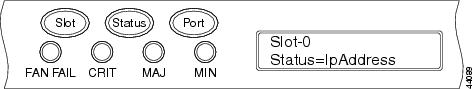
ステップ 1![]() ONS 15454 の前面パネルで、LCD に Node が表示されるまで Slot ボタンを繰り返し押します。
ONS 15454 の前面パネルで、LCD に Node が表示されるまで Slot ボタンを繰り返し押します。
ステップ 2![]() 次の表示が現れるまで、 Port ボタンを繰り返し押します。
次の表示が現れるまで、 Port ボタンを繰り返し押します。
•![]() ノードの IP アドレスを変更する場合は、Status=IpAddress(図3-1)
ノードの IP アドレスを変更する場合は、Status=IpAddress(図3-1)
•![]() ノードのネットワーク マスクを変更する場合は、Status=Net Mask
ノードのネットワーク マスクを変更する場合は、Status=Net Mask
•![]() デフォルト ルータの IP アドレスを変更する場合は、Status=Default Rtr
デフォルト ルータの IP アドレスを変更する場合は、Status=Default Rtr
ステップ 3![]() Status ボタンを押して、ノードの IP アドレス(図3-2)、ノードのサブネット マスク長、またはデフォルト ルータの IP アドレスを表示します。
Status ボタンを押して、ノードの IP アドレス(図3-2)、ノードのサブネット マスク長、またはデフォルト ルータの IP アドレスを表示します。
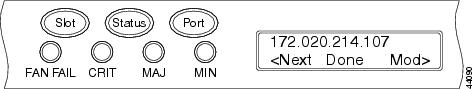
ステップ 4![]() Slot ボタンを押して、変更が必要な IP アドレスまたはサブネット マスクのディジットに移動します。選択したディジットがフラッシュします。
Slot ボタンを押して、変更が必要な IP アドレスまたはサブネット マスクのディジットに移動します。選択したディジットがフラッシュします。
ヒント Slot、Status、および Port の各ボタンの位置は、LCD のコマンドの位置に対応しています。たとえば、図3-2 では、Slot ボタンを押して Next コマンドを呼び出し、Port ボタンを押して Done コマンドを呼び出します。
ステップ 5![]() Port ボタンを押して IP アドレスまたはサブネット マスクの該当するディジットに進みます。
Port ボタンを押して IP アドレスまたはサブネット マスクの該当するディジットに進みます。
ステップ 6![]() 変更が完了したら、 Status ボタンを押して Node メニューに戻ります。
変更が完了したら、 Status ボタンを押して Node メニューに戻ります。
ステップ 7![]() Save Configuration オプションが表示されるまで、 Port ボタンを繰り返し押します(図3-3)。
Save Configuration オプションが表示されるまで、 Port ボタンを繰り返し押します(図3-3)。
図3-3 Save Configuration オプションの選択
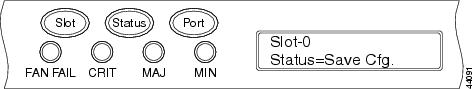
ステップ 8![]() Status ボタンを押して、Save Configuration オプションを選択します。
Status ボタンを押して、Save Configuration オプションを選択します。
「Save and REBOOT」というメッセージが表示されます(図3-4)。
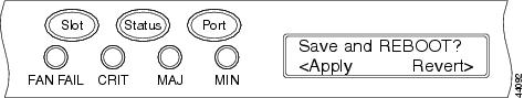
ステップ 9![]() Slot ボタンを押して新しい IP アドレス設定を適用するか、 Port を押して設定をキャンセルします。
Slot ボタンを押して新しい IP アドレス設定を適用するか、 Port を押して設定をキャンセルします。
新しい設定を保存すると、TCC2/TCC2P カードがリブートされます。リブート中に、「Saving Changes - TCC Reset」というメッセージが LCD に表示されます。TCC2/TCC2P のリブートが完了すると、LCD は通常の交互表示に戻ります。
(注) IP アドレスとデフォルト ルータは、同じサブネット上に設定する必要があります。サブネットが異なる場合は、設定を適用できません。
DLP-G264 ノード セキュリティ モードのイネーブル化
この作業では、ONS 15454 のセキュリティ モードをイネーブルにします。セキュリティ モードをイネーブルにすると、2 つの IP アドレスがノードに割り当てられます。1 つのアドレスがバックプレーンの LAN ポートに割り当てられ、もう 1 つのアドレスが TCC2P RJ-45 TCP/IP(LAN)ポートに割り当てられます。 |
|
(注) この作業を実行すると、ノードがリブートされ、CTC コンピュータとノードの接続が一時的に切断されます。
ステップ 1![]() Provisioning > Security> Data Comm タブをクリックします。
Provisioning > Security> Data Comm タブをクリックします。
ステップ 3![]() Change Secure Mode ウィザード ページの情報を確認し、 Next をクリックします。
Change Secure Mode ウィザード ページの情報を確認し、 Next をクリックします。
ステップ 4![]() TCC Ethernet Port ページで、TCC2P LAN(TCP/IP)ポートの IP アドレスとサブネット マスクを入力します。バックプレーンの LAN ポートおよび ONS 15454 のデフォルト ルータとは異なるサブネットの IP アドレスを指定する必要があります。
TCC Ethernet Port ページで、TCC2P LAN(TCP/IP)ポートの IP アドレスとサブネット マスクを入力します。バックプレーンの LAN ポートおよび ONS 15454 のデフォルト ルータとは異なるサブネットの IP アドレスを指定する必要があります。
ステップ 6![]() Backplane Ethernet Port ページでは、バックプレーンの IP アドレス、サブネット マスク、およびデフォルト ルータを変更します(ONS 15454 ネットワークに変更がなければ、通常、これらのフィールドを変更する必要はありません)。
Backplane Ethernet Port ページでは、バックプレーンの IP アドレス、サブネット マスク、およびデフォルト ルータを変更します(ONS 15454 ネットワークに変更がなければ、通常、これらのフィールドを変更する必要はありません)。
ステップ 8![]() SOCKS Proxy Server Settings ページで、次のいずれかのオプションを選択します。
SOCKS Proxy Server Settings ページで、次のいずれかのオプションを選択します。
•![]() External Network Element(ENE):このボックスをオンにすると、CTC コンピュータは、接続された ONS 15454 にだけ表示されます。コンピュータは DCC 接続ノードに対しては表示されません。また、ファイアウォールがイネーブルになり、ノードで DCC と LAN ポート間の IP トラフィックがルーティングされなくなります。
External Network Element(ENE):このボックスをオンにすると、CTC コンピュータは、接続された ONS 15454 にだけ表示されます。コンピュータは DCC 接続ノードに対しては表示されません。また、ファイアウォールがイネーブルになり、ノードで DCC と LAN ポート間の IP トラフィックがルーティングされなくなります。
•![]() Gateway Network Element(GNE):このボックスをオンにすると、CTC コンピュータは他の DCC 接続ノードに表示されます。ノードで、DCC と LAN ポート間の IP トラフィックがルーティングされなくなります。
Gateway Network Element(GNE):このボックスをオンにすると、CTC コンピュータは他の DCC 接続ノードに表示されます。ノードで、DCC と LAN ポート間の IP トラフィックがルーティングされなくなります。
(注) セキュア モードをイネーブルにすると、SOCKS プロキシ サーバが自動的にイネーブルになります。
30~40 秒以内に TCC2P がリブートされます。CTC がネットワーク ビューに切り替わり、CTC Alerts ダイアログボックスが表示されます。ネットワーク ビューでは、ノードの表示が灰色に変わり、接続解除状態が表示されます。
ステップ 10![]() CTC Alerts ダイアログボックスで、 Close をクリックします。リブートが終了するまで待機します(数分かかることがあります)。
CTC Alerts ダイアログボックスで、 Close をクリックします。リブートが終了するまで待機します(数分かかることがあります)。
ステップ 11![]() 接続解除状態の表示が消えたら、次のステップを実行して、CTC および LCD に表示されているバックプレーンの IP アドレスを非表示にします。バックプレーンの IP アドレスを非表示にしない場合は、ステップ 12 に進みます。
接続解除状態の表示が消えたら、次のステップを実行して、CTC および LCD に表示されているバックプレーンの IP アドレスを非表示にします。バックプレーンの IP アドレスを非表示にしない場合は、ステップ 12 に進みます。
b.![]() Provisioning > Security> Data Comm タブをクリックします。
Provisioning > Security> Data Comm タブをクリックします。
c.![]() LCD IP Setting フィールドで、 Suppress Display を選択します。これによって、ONS 15454 の LCD の IP アドレスが非表示になります。
LCD IP Setting フィールドで、 Suppress Display を選択します。これによって、ONS 15454 の LCD の IP アドレスが非表示になります。
d.![]() Suppress CTC IP Address チェックボックスをオンにします。これによって、CTC 情報エリアおよび Provisioning > Security > Data Comm タブの IP アドレスが非表示になります。
Suppress CTC IP Address チェックボックスをオンにします。これによって、CTC 情報エリアおよび Provisioning > Security > Data Comm タブの IP アドレスが非表示になります。
(注) セキュア モードをオンにすると、TCC2P の IP アドレスがノードの IP アドレスになります。
ステップ 1![]() ノード ビューで、 Provisioning > Network タブをクリックします。
ノード ビューで、 Provisioning > Network タブをクリックします。
ステップ 2![]() Static Routing タブをクリックします。 Create をクリックします。
Static Routing タブをクリックします。 Create をクリックします。
ステップ 3![]() Create Static Route ダイアログボックスで次の情報を入力します。
Create Static Route ダイアログボックスで次の情報を入力します。
•![]() Destination:CTC を実行しているコンピュータの IP アドレスを入力します。アクセス先を 1 つのコンピュータに制限するには、完全な IP アドレスとサブネット マスク 255.255.255.255 を入力します。192.168.1.0 サブネット上のすべてのコンピュータへのアクセスを許可するには、192.168.1.0 とサブネット マスク 255.255.255.0 を入力します。宛先として 0.0.0.0 を入力すると、ルータに接続しているすべての CTC コンピュータへのアクセスが許可されます。
Destination:CTC を実行しているコンピュータの IP アドレスを入力します。アクセス先を 1 つのコンピュータに制限するには、完全な IP アドレスとサブネット マスク 255.255.255.255 を入力します。192.168.1.0 サブネット上のすべてのコンピュータへのアクセスを許可するには、192.168.1.0 とサブネット マスク 255.255.255.0 を入力します。宛先として 0.0.0.0 を入力すると、ルータに接続しているすべての CTC コンピュータへのアクセスが許可されます。
•![]() Mask:サブネット マスクを入力します。宛先がホスト ルート(つまり、1 つの CTC コンピュータ)の場合は、32 ビットのサブネット マスク(255.255.255.255)を入力します。宛先がサブネットの場合は、255.255.255.0 のようにサブネット マスクを調整します。宛先が 0.0.0.0 の場合、CTC によって自動的にサブネット マスク 0.0.0.0 が入力され、すべての CTC コンピュータへのアクセスが許可されます。この値は変更できません。
Mask:サブネット マスクを入力します。宛先がホスト ルート(つまり、1 つの CTC コンピュータ)の場合は、32 ビットのサブネット マスク(255.255.255.255)を入力します。宛先がサブネットの場合は、255.255.255.0 のようにサブネット マスクを調整します。宛先が 0.0.0.0 の場合、CTC によって自動的にサブネット マスク 0.0.0.0 が入力され、すべての CTC コンピュータへのアクセスが許可されます。この値は変更できません。
•![]() Next Hop:ルータ ポートの IP アドレスを入力するか、CTC コンピュータがノードに直接接続されている場合はノードの IP アドレスを入力します。
Next Hop:ルータ ポートの IP アドレスを入力するか、CTC コンピュータがノードに直接接続されている場合はノードの IP アドレスを入力します。
•![]() Cost:ONS 15454 とコンピュータの間のホップ数を入力します。
Cost:ONS 15454 とコンピュータの間のホップ数を入力します。
ステップ 4![]() OK をクリックします。Static Route ウィンドウにスタティック ルートが表示されることを確認します。
OK をクリックします。Static Route ウィンドウにスタティック ルートが表示されることを確認します。
(注) スタティック ルートのネットワーキングの例は、第 22 章「接続リファレンスの管理」にあります。
この作業では、ONS 15454 の OSPF をイネーブルにします。ONS 15454 を OSPF に対応したネットワークに追加する場合に、この作業を実行します。 |
|
| ONS 15454 の接続先のルータでプロビジョニングされている OSPF エリア ID、Hello インターバルと Dead インターバル、および認証鍵(OSPF 認証がイネーブルの場合)が必要です。 |
|
ステップ 1![]() ノード ビューで、 Provisioning > Network > OSPF タブをクリックします。
ノード ビューで、 Provisioning > Network > OSPF タブをクリックします。
ステップ 2![]() OSPF ペインの左上部で次の項目を指定します。
OSPF ペインの左上部で次の項目を指定します。
•![]() DCC/GCC OSPF Area ID Table:ドット付き 10 進形式で、一意の OSPF エリア ID としての ONS 15454 ノードを示す数字を入力します。Area ID には 000.000.000.000 から 255.255.255.255 の間の任意の数字を使用できますが、LAN OSPF エリアに対して一意である必要があります。
DCC/GCC OSPF Area ID Table:ドット付き 10 進形式で、一意の OSPF エリア ID としての ONS 15454 ノードを示す数字を入力します。Area ID には 000.000.000.000 から 255.255.255.255 の間の任意の数字を使用できますが、LAN OSPF エリアに対して一意である必要があります。
•![]() SDCC Metric:この値は、通常は変更しません。セクション DCC を介したパケット送信コストを設定する値であり、OSPF ルータが最短パスを計算するために使用します。この値は、常に LAN メトリックより大きな値にする必要があります。SDCC メトリックのデフォルト値は 100 です。
SDCC Metric:この値は、通常は変更しません。セクション DCC を介したパケット送信コストを設定する値であり、OSPF ルータが最短パスを計算するために使用します。この値は、常に LAN メトリックより大きな値にする必要があります。SDCC メトリックのデフォルト値は 100 です。
•![]() LDCC Metric:ライン DCC を介したパケット送信コストを設定します。この値は、常に SDCC メトリックより小さな値にする必要があります。デフォルトの LDCC メトリックは 33 です。通常は変更しません。
LDCC Metric:ライン DCC を介したパケット送信コストを設定します。この値は、常に SDCC メトリックより小さな値にする必要があります。デフォルトの LDCC メトリックは 33 です。通常は変更しません。
ステップ 3![]() OSPF on LAN エリアで次の項目を指定します。
OSPF on LAN エリアで次の項目を指定します。
•![]() OSPF active on LAN:オンにすると、ONS 15454 OSPF トポロジーを LAN 上の OSPF ルータにアドバタイジングできます。このフィールドは、OSPF ルータに直接接続されている ONS 15454 ノードでオンにします。
OSPF active on LAN:オンにすると、ONS 15454 OSPF トポロジーを LAN 上の OSPF ルータにアドバタイジングできます。このフィールドは、OSPF ルータに直接接続されている ONS 15454 ノードでオンにします。
•![]() LAN Port Area ID:ONS 15454 が接続されているルータ ポートの OSPF エリア ID(ドット付き 10 進形式)を入力します(この数値は、DCC/GCC OSPF エリア ID とは異なります)。
LAN Port Area ID:ONS 15454 が接続されているルータ ポートの OSPF エリア ID(ドット付き 10 進形式)を入力します(この数値は、DCC/GCC OSPF エリア ID とは異なります)。
ステップ 4![]() デフォルトでは、OSPF は No Authentication に設定されています。OSPF ルータが認証を必要とする場合は、次のステップを実行します。その必要がない場合は、ステップ 5 に進みます。
デフォルトでは、OSPF は No Authentication に設定されています。OSPF ルータが認証を必要とする場合は、次のステップを実行します。その必要がない場合は、ステップ 5 に進みます。
a.![]() No Authentication ボタンをクリックします。
No Authentication ボタンをクリックします。
b.![]() Edit Authentication Key ダイアログボックスで次の項目を指定します。
Edit Authentication Key ダイアログボックスで次の項目を指定します。
•![]() Type: Simple Password を選択します。
Type: Simple Password を選択します。
•![]() Enter Authentication Key:パスワードを入力します。
Enter Authentication Key:パスワードを入力します。
•![]() Confirm Authentication Key:確認のために同じパスワードを入力します。
Confirm Authentication Key:確認のために同じパスワードを入力します。
認証ボタンのラベルが Simple Password に変わります。
ステップ 5![]() OSPF の優先順位とインターバルの設定をプロビジョニングします。
OSPF の優先順位とインターバルの設定をプロビジョニングします。
OSPF の優先順位とインターバルのデフォルト値は、OSPF ルータで最もよく使用されるデフォルト値です。これらのデフォルト値が、ONS 15454 の接続先の OSPF ルータで使用される値と一致していることを確認します。
•![]() Router Priority:サブネットの代表ルータを選択します。
Router Priority:サブネットの代表ルータを選択します。
•![]() Hello Interval (sec):OSPF ルータが送信する OSPF hello パケット アドバタイズメントの間隔の秒数を設定します。デフォルトは 10 秒です。
Hello Interval (sec):OSPF ルータが送信する OSPF hello パケット アドバタイズメントの間隔の秒数を設定します。デフォルトは 10 秒です。
•![]() Dead Interval:OSPF ルータのパケットが表示されなくなってから近隣ルータがそのルータのダウンを宣言するまでの秒数を設定します。デフォルトは 40 秒です。
Dead Interval:OSPF ルータのパケットが表示されなくなってから近隣ルータがそのルータのダウンを宣言するまでの秒数を設定します。デフォルトは 40 秒です。
•![]() Transit Delay (sec):サービスの速度を指定します。デフォルトは 1 秒です。
Transit Delay (sec):サービスの速度を指定します。デフォルトは 1 秒です。
•![]() Retransmit Interval (sec):パケットを再送するまでの経過時間を設定します。デフォルトは 5 秒です。
Retransmit Interval (sec):パケットを再送するまでの経過時間を設定します。デフォルトは 5 秒です。
•![]() LAN Metric: LAN を介したパケット送信コストを設定します。 この値は、常に SDCC メトリックより小さな値にする必要があります。デフォルトは 10 です。
LAN Metric: LAN を介したパケット送信コストを設定します。 この値は、常に SDCC メトリックより小さな値にする必要があります。デフォルトは 10 です。
ステップ 6![]() エリア範囲テーブルが必要な場合は、OSPF Area Range Table の下に作成します。
エリア範囲テーブルが必要な場合は、OSPF Area Range Table の下に作成します。
(注) エリア範囲テーブルは、OSPF エリア境界外にある情報を統合するテーブルです。ONS 15454 OSPF エリアにある 1 つの ONS 15454 が OSPF ルータに接続されます。このノードにあるエリア範囲テーブルは、ルータに対して、ONS 15454 OSPF エリア内に存在する他のノードを指し示します。
a.![]() OSPF Area Range Table の下で、 Create をクリックします。
OSPF Area Range Table の下で、 Create をクリックします。
b.![]() Create Area Range ダイアログボックスで次の項目を指定します。
Create Area Range ダイアログボックスで次の項目を指定します。
•![]() Range Address:OSPF エリア内にある ONS 15454 ノードのエリア IP アドレスを入力します。たとえば、ONS 15454 OSPF エリア内に IP アドレスが 10.10.20.100、10.10.30.150、10.10.40.200、および 10.10.50.250 のノードがある場合、範囲アドレスは 10.10.0.0 となります。
Range Address:OSPF エリア内にある ONS 15454 ノードのエリア IP アドレスを入力します。たとえば、ONS 15454 OSPF エリア内に IP アドレスが 10.10.20.100、10.10.30.150、10.10.40.200、および 10.10.50.250 のノードがある場合、範囲アドレスは 10.10.0.0 となります。
•![]() Range Area ID:ONS 15454 ノードの OSPF エリア ID を入力します。これは、DCC OSPF Area ID フィールドの ID または Area ID for LAN Port フィールドの ID のいずれかになります。
Range Area ID:ONS 15454 ノードの OSPF エリア ID を入力します。これは、DCC OSPF Area ID フィールドの ID または Area ID for LAN Port フィールドの ID のいずれかになります。
•![]() Mask Length:サブネット マスク長を入力します。上記の範囲アドレスの例では、この値は 16 になります。
Mask Length:サブネット マスク長を入力します。上記の範囲アドレスの例では、この値は 16 になります。
•![]() Advertise:OSPF 範囲テーブルをアドバタイジングする場合はオンにします。
Advertise:OSPF 範囲テーブルをアドバタイジングする場合はオンにします。
ステップ 7![]() すべての OSPF エリアはエリア 0 に接続されている必要があります。ONS 15454 OSPF エリアが物理的にエリア 0 に接続されていない場合は、次のステップに従って仮想リンク テーブルを作成し、接続されていないエリアにエリア 0 への論理パスを提供します。
すべての OSPF エリアはエリア 0 に接続されている必要があります。ONS 15454 OSPF エリアが物理的にエリア 0 に接続されていない場合は、次のステップに従って仮想リンク テーブルを作成し、接続されていないエリアにエリア 0 への論理パスを提供します。
a.![]() OSPF Virtual Link Table の下で、 Create をクリックします。
OSPF Virtual Link Table の下で、 Create をクリックします。
b.![]() Create Virtual Link ダイアログボックスで、次のフィールドを設定します。OSPF の設定は、ONS 15454 OSPF エリアの OSPF 設定と一致する必要があります。
Create Virtual Link ダイアログボックスで、次のフィールドを設定します。OSPF の設定は、ONS 15454 OSPF エリアの OSPF 設定と一致する必要があります。
•![]() Transit Delay (sec):サービスの速度。デフォルトは 1 秒です。
Transit Delay (sec):サービスの速度。デフォルトは 1 秒です。
•![]() Hello Int (sec):OSPF ルータが送信する OSPF hello パケット アドバタイズメントの間隔の秒数。デフォルトは 10 秒です。
Hello Int (sec):OSPF ルータが送信する OSPF hello パケット アドバタイズメントの間隔の秒数。デフォルトは 10 秒です。
•![]() Auth Type:ONS 15454 の接続先のルータが認証を使用する場合は、 Simple Password を選択します。それ以外の場合は、 No Authentication を選択します。
Auth Type:ONS 15454 の接続先のルータが認証を使用する場合は、 Simple Password を選択します。それ以外の場合は、 No Authentication を選択します。
•![]() Retransmit Int (sec):パケットを再送するまでの経過時間を設定します。デフォルトは 5 秒です。
Retransmit Int (sec):パケットを再送するまでの経過時間を設定します。デフォルトは 5 秒です。
•![]() Dead Int (sec):OSPF ルータのパケットがわからなくなってから近隣ルータがそのルータのダウンを宣言するまでの秒数を設定します。デフォルトは 40 秒です。
Dead Int (sec):OSPF ルータのパケットがわからなくなってから近隣ルータがそのルータのダウンを宣言するまでの秒数を設定します。デフォルトは 40 秒です。
ステップ 8![]() ONS 15454 OSPF エリアのデータを入力したら、 Apply をクリックします。
ONS 15454 OSPF エリアのデータを入力したら、 Apply をクリックします。
エリア ID を変更した場合は、一度に 1 つずつ TCC2/TCC2P カードがリセットされます。リセットには約 10~15 分かかります。表3-1は、TCC2/TCC2P リセット中の LED の動作を示しています。
この作業では、ONS 15454 の RIP をイネーブルにします。ONS 15454 を RIP に対応したネットワークに追加する場合に、この作業を実行します。 |
|
| DCC 接続されていないノードに ONS 15454 からルーティング情報を伝えるために、ONS 15454 に隣接するルータへのスタティック ルートを作成する必要があります。 |
|
ステップ 1![]() ノード ビューで、 Provisioning > Network > RIP タブをクリックします。
ノード ビューで、 Provisioning > Network > RIP タブをクリックします。
ステップ 2![]() RIP をイネーブルにする場合は、 RIP Active チェックボックスをオンにします。
RIP をイネーブルにする場合は、 RIP Active チェックボックスをオンにします。
ステップ 3![]() ネットワークでサポートされているバージョンに応じて、ドロップダウン リストから RIP Version 1 または RIP Version 2 を選択します。
ネットワークでサポートされているバージョンに応じて、ドロップダウン リストから RIP Version 1 または RIP Version 2 を選択します。
ステップ 4![]() RIP メトリックを設定します。RIP メトリックは 1~15 までの数値に設定できます。これは、ホップ数を表します。
RIP メトリックを設定します。RIP メトリックは 1~15 までの数値に設定できます。これは、ホップ数を表します。
ステップ 5![]() デフォルトでは、RIP は No Authentication に設定されています。ONS 15454 の接続先のルータが認証を必要とする場合は、次のステップを実行します。その必要がない場合は、ステップ 6 に進みます。
デフォルトでは、RIP は No Authentication に設定されています。ONS 15454 の接続先のルータが認証を必要とする場合は、次のステップを実行します。その必要がない場合は、ステップ 6 に進みます。
a.![]() No Authentication ボタンをクリックします。
No Authentication ボタンをクリックします。
b.![]() Edit Authentication Key ダイアログボックスで次の項目を指定します。
Edit Authentication Key ダイアログボックスで次の項目を指定します。
•![]() Type: Simple Password を選択します。
Type: Simple Password を選択します。
•![]() Enter Authentication Key:パスワードを入力します。
Enter Authentication Key:パスワードを入力します。
•![]() Confirm Authentication Key:確認のために同じパスワードを入力します。
Confirm Authentication Key:確認のために同じパスワードを入力します。
認証ボタンのラベルが Simple Password に変わります。
ステップ 6![]() アドレス サマリーを入力する場合は、次のステップを実行します。その必要がない場合は、ステップ 7 に進みます。アドレス サマリーは、ONS 15454 がゲートウェイ NE である場合だけ入力します。ゲートウェイ NE では、異なるサブネットの複数の外部 ONS 15454 の NE が IP アドレスによって接続されています。
アドレス サマリーを入力する場合は、次のステップを実行します。その必要がない場合は、ステップ 7 に進みます。アドレス サマリーは、ONS 15454 がゲートウェイ NE である場合だけ入力します。ゲートウェイ NE では、異なるサブネットの複数の外部 ONS 15454 の NE が IP アドレスによって接続されています。
a.![]() RIP Address Summary エリアで、 Create をクリックします。
RIP Address Summary エリアで、 Create をクリックします。
b.![]() Create Address Summary ダイアログボックスで次の情報を入力します。
Create Address Summary ダイアログボックスで次の情報を入力します。
•![]() Summary Address:サマリー IP アドレスを入力します。
Summary Address:サマリー IP アドレスを入力します。
•![]() Mask Length:上矢印と下矢印を使用してサブネット マスク長を入力します。
Mask Length:上矢印と下矢印を使用してサブネット マスク長を入力します。
•![]() Hops:ホップ数を入力します。ホップ数が少ないほど、優先順位が高くなります。
Hops:ホップ数を入力します。ホップ数が少ないほど、優先順位が高くなります。
NTP-G27 ファイアウォール アクセスを目的とした ONS 15454 の設定
この手順では、ONS 15454 ノードおよび CTC コンピュータにファイアウォールを介してアクセスするためのプロビジョニングを行います。 |
|
ステップ 1![]() ファイアウォールの背後にあるノードにログインします。手順については、「G46 CTC へのログイン」を参照してください。すでにログインしている場合は、ステップ 2 に進みます。
ファイアウォールの背後にあるノードにログインします。手順については、「G46 CTC へのログイン」を参照してください。すでにログインしている場合は、ステップ 2 に進みます。
ステップ 2![]() 「G61 ONS 15454 における IIOP リスナー ポートのプロビジョニング」の作業を行います。
「G61 ONS 15454 における IIOP リスナー ポートのプロビジョニング」の作業を行います。
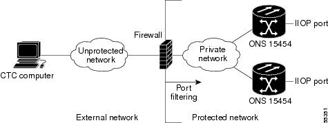
図3-5 は、ONS 15454 ノードが保護ネットワーク内にあり、CTC コンピュータが外部ネットワークにあるケースを示しています。コンピュータから ONS 15454 ノードにアクセスするには、ファイアウォール管理者が指定した IIOP リスナー ポートを ONS 15454 上でプロビジョニングする必要があります。
ステップ 3![]() CTC コンピュータがファイアウォールの背後にある場合は、「G62 CTC コンピュータにおける IIOP リスナー ポートのプロビジョニング」の作業を行います。
CTC コンピュータがファイアウォールの背後にある場合は、「G62 CTC コンピュータにおける IIOP リスナー ポートのプロビジョニング」の作業を行います。
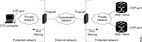
図3-6 は、CTC コンピュータと ONS 15454 がファイアウォールの背後にあるケースを示しています。コンピュータから ONS 15454 にアクセスするには、CTC コンピュータと ONS 15454 上で IIOP ポートをプロビジョニングする必要があります。
図3-6 ファイアウォールの背後にある CTC コンピュータ と ONS 15454ノード
DLP-G61 ONS 15454 における IIOP リスナー ポートのプロビジョニング
この作業では、ONS 15454 ノード上で IIOP リスナー ポートを設定し、ファイアウォールの背後にある ONS 15454 にアクセスできるようにします。 |
|
(注) Enable SOCKS Proxy Server on port 1080 チェックボックスがオンになっている場合、CTC ではポート 1080 が使用され、ここで設定した IIOP ポート設定は無視されます。後に Enable SOCKS Proxy Server チェックボックスをオフにした場合は、ここで設定した IIOP リスナー ポートが使用されます。
ステップ 1![]() ノード ビューで、 Provisioning > Network > General タブをクリックします。
ノード ビューで、 Provisioning > Network > General タブをクリックします。
ステップ 2![]() TCC CORBA (IIOP) Listener Port エリアで、次のリスナー ポート オプションを選択します。
TCC CORBA (IIOP) Listener Port エリアで、次のリスナー ポート オプションを選択します。
•![]() TCC Fixed(デフォルト):ポート 57790 を使用します。ファイアウォールの同じ側にある ONS 15454 ノードに接続する場合、またはファイアウォールを使用しない場合(デフォルト)に適したオプションです。ポート 57790 が開いている場合は、ファイアウォールを介したアクセスにこのオプションを使用することもできます。
TCC Fixed(デフォルト):ポート 57790 を使用します。ファイアウォールの同じ側にある ONS 15454 ノードに接続する場合、またはファイアウォールを使用しない場合(デフォルト)に適したオプションです。ポート 57790 が開いている場合は、ファイアウォールを介したアクセスにこのオプションを使用することもできます。
•![]() Standard Constant:CORBA のデフォルト ポート番号であるポート 683 を使用します。
Standard Constant:CORBA のデフォルト ポート番号であるポート 683 を使用します。
•![]() Other Constant:ポート 683 を使用しない場合は、ファイアウォール管理者が指定する IIOP ポートを入力します。
Other Constant:ポート 683 を使用しない場合は、ファイアウォール管理者が指定する IIOP ポートを入力します。
ステップ 4![]() 「Change Network Configuration」というメッセージが表示されたら、 Yes をクリックします。
「Change Network Configuration」というメッセージが表示されたら、 Yes をクリックします。
両方の ONS 15454 TCC2/TCC2P カードを、一度に 1 つずつリブートします。リブートには約 15 分かかります。
DLP-G62 CTC コンピュータにおける IIOP リスナー ポートのプロビジョニング
この作業では、CTC 上の IIOP リスナー ポートを選択します。ファイアウォールの後ろで CTC を稼働させている PC の場合、この作業を実行します。 |
|
ステップ 1![]() Edit メニューで、 Preferences を選択します。
Edit メニューで、 Preferences を選択します。
ステップ 2![]() Preferences ダイアログボックスで Firewall タブをクリックします。
Preferences ダイアログボックスで Firewall タブをクリックします。
ステップ 3![]() CTC CORBA (IIOP) Listener Port エリアで、リスナー ポート オプションを選択します。
CTC CORBA (IIOP) Listener Port エリアで、リスナー ポート オプションを選択します。
•![]() Variable(デフォルト):ファイアウォール内部から ONS 15454 ノードに接続する場合、またはファイアウォールを使用しない場合(デフォルト)に使用します。
Variable(デフォルト):ファイアウォール内部から ONS 15454 ノードに接続する場合、またはファイアウォールを使用しない場合(デフォルト)に使用します。
•![]() Standard Constant:CORBA のデフォルト ポート番号であるポート 683 を使用します。
Standard Constant:CORBA のデフォルト ポート番号であるポート 683 を使用します。
•![]() Other Constant:ポート 683 を使用しない場合は、管理者が定義した IIOP ポートを入力します。
Other Constant:ポート 683 を使用しない場合は、管理者が定義した IIOP ポートを入力します。
ステップ 4![]() Apply をクリックします。ポートの変更は次回の CTC ログイン時に適用される旨の警告メッセージが表示されます。
Apply をクリックします。ポートの変更は次回の CTC ログイン時に適用される旨の警告メッセージが表示されます。
ステップ 6![]() Preferences ダイアログボックスで OK をクリックします。
Preferences ダイアログボックスで OK をクリックします。
ステップ 7![]() IIOP ポートを使用して ONS 15454 にアクセスするには、CTC からログアウトしてログインし直します(ログアウトするには、File メニューから Exit を選択します)。
IIOP ポートを使用して ONS 15454 にアクセスするには、CTC からログアウトしてログインし直します(ログアウトするには、File メニューから Exit を選択します)。
(注) この手順では、ルータやサード パーティ製の NE を含む非 ONS 機器のプロビジョニングが必要になります。これらのプロビジョニングに問題がなければ作業を開始してください。
ステップ 1![]() OSI ルーティング モードをプロビジョニングするノードで 「G46 CTC へのログイン」 を実行します。すでにログインしている場合は、ステップ 2 に進みます。
OSI ルーティング モードをプロビジョニングするノードで 「G46 CTC へのログイン」 を実行します。すでにログインしている場合は、ステップ 2 に進みます。
•![]() 「G132 OSI のプロビジョニング」:最初にこの手順を実行します。
「G132 OSI のプロビジョニング」:最初にこの手順を実行します。
•![]() 「G284 TARP オペレーティング パラメータのプロビジョニング」:次にこの作業を実行します。
「G284 TARP オペレーティング パラメータのプロビジョニング」:次にこの作業を実行します。
•![]() 「G285 静的な TID to NSAP エントリの TARP Data Cache への追加」:この作業は、必要に応じて実行します。
「G285 静的な TID to NSAP エントリの TARP Data Cache への追加」:この作業は、必要に応じて実行します。
•![]() 「G287 TARP MAT エントリの追加」:この作業は、必要に応じて実行します。
「G287 TARP MAT エントリの追加」:この作業は、必要に応じて実行します。
•![]() 「G288 OSI ルータのプロビジョング」:この作業は、必要に応じて実行します。
「G288 OSI ルータのプロビジョング」:この作業は、必要に応じて実行します。
•![]() 「G289 追加のマニュアル エリア アドレスのプロビジョニング」:この作業は、必要に応じて実行します。
「G289 追加のマニュアル エリア アドレスのプロビジョニング」:この作業は、必要に応じて実行します。
•![]() 「G290 LAN インターフェイスでの OSI サブネットのイネーブル化」:この作業は、必要に応じて実行します。
「G290 LAN インターフェイスでの OSI サブネットのイネーブル化」:この作業は、必要に応じて実行します。
•![]() 「G291 IP-over-CLNS トンネルの作成」:この作業は、必要に応じて実行します。
「G291 IP-over-CLNS トンネルの作成」:この作業は、必要に応じて実行します。
DLP-G283 OSI ルーティング モードのプロビジョング
この作業では、OSI ルーティング モードをプロビジョングします。DCN 通信に OSI プロトコル スタックを使用しているサード パーティ製の NE のネットワークに対して ONS 15454 を接続する場合、この作業を実行します。 |
|
(注) ONS 15454 ノードでは、3 つの仮想ルータをプロビジョニングできます。ノードのプライマリ NSAP アドレスは Router 1 のプライマリ マニュアル エリア アドレスです。プライマリ NSAP を編集するには、Router 1 のプライマリ マニュアル エリア アドレスを編集する必要があります。Router サブタブの Router 1 をイネーブルにすると、アドレスを編集するための[Change Primary Area Address]ボタンを使用できます。
ステップ 1![]() OSI ルーティング モードをプロビジョニングするノードで 「G46 CTC へのログイン」 を実行します。すでにログインしている場合は、ステップ 2 に進みます。
OSI ルーティング モードをプロビジョニングするノードで 「G46 CTC へのログイン」 を実行します。すでにログインしている場合は、ステップ 2 に進みます。
ステップ 2![]() ノード ビューで、 Provisioning > OSI タブをクリックします。
ノード ビューで、 Provisioning > OSI タブをクリックします。
•![]() End System:ONS 15454 は End System(ES)機能を実行します。また、OSI エリア内にあるノードとの通信に、Intermediate System(IS)を使用します。
End System:ONS 15454 は End System(ES)機能を実行します。また、OSI エリア内にあるノードとの通信に、Intermediate System(IS)を使用します。
(注) 複数の仮想ルータがイネーブルになっている場合、ES のルーティング モードは使用できません。
•![]() Intermediate System Level 1:ONS 15454 は OSI IS 機能を実行します。また、OSI エリア内の IS ノードおよび ES ノードと通信します。OSI エリア外の IS ノードおよび ES ノードとの通信には、IS L1/L2 ノードに依存します。
Intermediate System Level 1:ONS 15454 は OSI IS 機能を実行します。また、OSI エリア内の IS ノードおよび ES ノードと通信します。OSI エリア外の IS ノードおよび ES ノードとの通信には、IS L1/L2 ノードに依存します。
•![]() Intermediate System Level 1/Level 2:ONS 15454 は、IS 機能を実行します。また、OSI エリア内の IS ノードおよび ES ノードと通信します。また、他の OSI エリア内の IS L1/L2 ノードと通信します。このオプションを選択する前に、次の内容を確認してください。
Intermediate System Level 1/Level 2:ONS 15454 は、IS 機能を実行します。また、OSI エリア内の IS ノードおよび ES ノードと通信します。また、他の OSI エリア内の IS L1/L2 ノードと通信します。このオプションを選択する前に、次の内容を確認してください。
–![]() ノードが、異なる OSI エリアの他の IS Level 1/Level 2 ノードに接続されていること。
ノードが、異なる OSI エリアの他の IS Level 1/Level 2 ノードに接続されていること。
–![]() ノードが、IS L1/L2 としてプロビジョニングされているエリア内のすべてのノードに接続されていること。
ノードが、IS L1/L2 としてプロビジョニングされているエリア内のすべてのノードに接続されていること。
ステップ 4![]() 必要に応じて、LSP データ バッファを変更します。
必要に応じて、LSP データ バッファを変更します。
•![]() L1 LSP Buffer Size:Level 1 のリンク ステート PDU バッファ サイズを調整します。デフォルトは 512 に設定されています。この値は変更しないでください。
L1 LSP Buffer Size:Level 1 のリンク ステート PDU バッファ サイズを調整します。デフォルトは 512 に設定されています。この値は変更しないでください。
•![]() L2 LSP Buffer Size:Level 2 のリンク ステート PDU バッファ サイズを調整します。デフォルトは 512 に設定されています。この値は変更しないでください。
L2 LSP Buffer Size:Level 2 のリンク ステート PDU バッファ サイズを調整します。デフォルトは 512 に設定されています。この値は変更しないでください。
DLP-G284 TARP オペレーティング パラメータのプロビジョニング
この作業では、Target Identifier Address Resolution Protocol(TARP)オペレーティング パラメータをプロビジョニングします。このパラメータには、TARP Protocol Data Unit(PDU; プロトコル データ ユニット)の伝播、タイマー、Loop Detection Buffer(LDB)が含まれます。 |
|
ステップ 1![]() ノード ビューで、 Provisioning > OSI > TARP > Config タブをクリックします。
ノード ビューで、 Provisioning > OSI > TARP > Config タブをクリックします。
ステップ 2![]() 必要に応じて、次のパラメータのプロビジョニングを行います。
必要に応じて、次のパラメータのプロビジョニングを行います。
•![]() TARP PDUs L1 Propagation:オンになっている場合(デフォルト)、ノードに受信される(LDB に除外されていない)TARP Type 1 PDU が、Level 1 OSI エリア内の他の NE に伝播されます(Type 1 PDU は、Level 1 のルーティング エリア内で Target Identifier[TID]に一致するプロトコル アドレスを要求します)。NE が Type 1 のターゲットであり、PDU が PDU を受信した NE に伝播されていない場合、伝播は発生しません。
TARP PDUs L1 Propagation:オンになっている場合(デフォルト)、ノードに受信される(LDB に除外されていない)TARP Type 1 PDU が、Level 1 OSI エリア内の他の NE に伝播されます(Type 1 PDU は、Level 1 のルーティング エリア内で Target Identifier[TID]に一致するプロトコル アドレスを要求します)。NE が Type 1 のターゲットであり、PDU が PDU を受信した NE に伝播されていない場合、伝播は発生しません。
(注) TARP PDUs L1 Propagation パラメータは、Node Routing Area(Provisioning > OSI > Main Setup タブをクリック)が ES に設定されている場合は使用できません。
•![]() TARP PDUs L2 Propagation:オンになっている場合(デフォルト)、ノードに受信される(LDB に除外されていない)TARP Type 2 PDU が、Level 2 OSI エリア内の他の NE に伝播されます(Type 2 PDU は、Level 2 のルーティング エリア内で TID に一致するプロトコル アドレスを要求します)。NE が Type 2 のターゲットではなく、PDU が PDU を受信した NE に伝播されていない場合は、伝播が発生します。
TARP PDUs L2 Propagation:オンになっている場合(デフォルト)、ノードに受信される(LDB に除外されていない)TARP Type 2 PDU が、Level 2 OSI エリア内の他の NE に伝播されます(Type 2 PDU は、Level 2 のルーティング エリア内で TID に一致するプロトコル アドレスを要求します)。NE が Type 2 のターゲットではなく、PDU が PDU を受信した NE に伝播されていない場合は、伝播が発生します。
(注) TARP PDUs L2 Propagation パラメータは、Node Routing Area が IS Level 1/Level 2 にプロビジョニングされてる場合のみ使用できます。
•![]() TARP PDUs Origination:オンになっている場合(デフォルト)、次の機能を含め、ノードは TARP の機能をすべて実行します。
TARP PDUs Origination:オンになっている場合(デフォルト)、次の機能を含め、ノードは TARP の機能をすべて実行します。
–![]() TID to Network Service Access Point(NSAP)への解決要求(TARP Type 1 と Type 2 PDU に準拠)
TID to Network Service Access Point(NSAP)への解決要求(TARP Type 1 と Type 2 PDU に準拠)
–![]() NSAP to TID 要求(Type 5 PDU に準拠)
NSAP to TID 要求(Type 5 PDU に準拠)
(注) TARP Echo および NSAP to TID はサポートされていません。
•![]() TARP Data Cache:オンになっている場合(デフォルト)、ノードは TARP Data Cache(TDC)を維持します。TDC は、ノードで受信した TARP Type 3 PDU から作成され、さらに TARP Type 4 PDU(TID to NSAP 更新または修正)によって修正される TID to NSAP のペアのデータベースです。TARP 3 PDU は Type 1 と Type 2 PDU に応答します。また、TDC には TARP > Static TDC タブで入力した静的なエントリを含めることができます。
TARP Data Cache:オンになっている場合(デフォルト)、ノードは TARP Data Cache(TDC)を維持します。TDC は、ノードで受信した TARP Type 3 PDU から作成され、さらに TARP Type 4 PDU(TID to NSAP 更新または修正)によって修正される TID to NSAP のペアのデータベースです。TARP 3 PDU は Type 1 と Type 2 PDU に応答します。また、TDC には TARP > Static TDC タブで入力した静的なエントリを含めることができます。
(注) このパラメータは、TARP PDU Origination パラメータがイネーブルな場合にのみ使用されます。
•![]() L2 TARP Data Cache:オンになっている場合(デフォルト)、ノードが他の NE に要求を伝播する前に Type 2 要求に応じた NE の TID と NSAP が TDC に追加されます。
L2 TARP Data Cache:オンになっている場合(デフォルト)、ノードが他の NE に要求を伝播する前に Type 2 要求に応じた NE の TID と NSAP が TDC に追加されます。
(注) TARP Data Cache パラメータは、他の IS Level 1/Level 2 ノードに接続する IS Level 1/Level 2 ノード向けに設計されています。IS Level 1 ノードのパラメータをイネーブルにすることは推奨されていません。
•![]() LDB:オンになっている場合(デフォルト)、TARP ループ検出バッファがイネーブルになります。LDB は、TARP PDU が同一のサブネットで何度も送信されることを防ぎます。
LDB:オンになっている場合(デフォルト)、TARP ループ検出バッファがイネーブルになります。LDB は、TARP PDU が同一のサブネットで何度も送信されることを防ぎます。
(注) LDP パラメータは、Node Routing Mode が ES にプロビジョニングされている場合、または TARP PDUs L1 Propagation パラメータがイネーブルになっていない場合は使用されません。
•![]() LAN TARP Storm Suppression:オンになっている場合(デフォルト)、TARP ストーム抑制がイネーブルになります。この機能は、冗長 TARP PDU が LAN ネットワークに不必要に伝播されることを防ぎます。
LAN TARP Storm Suppression:オンになっている場合(デフォルト)、TARP ストーム抑制がイネーブルになります。この機能は、冗長 TARP PDU が LAN ネットワークに不必要に伝播されることを防ぎます。
•![]() Send Type 4 PDU on Startup:オンになっている場合、ONS 15454 の初回の起動中はTARP Type 4 PDU に依存します。Type 4 PDU は、TID または NSAP が NE で変更されたことを示します(デフォルトではイネーブルに設定されていません)。
Send Type 4 PDU on Startup:オンになっている場合、ONS 15454 の初回の起動中はTARP Type 4 PDU に依存します。Type 4 PDU は、TID または NSAP が NE で変更されたことを示します(デフォルトではイネーブルに設定されていません)。
•![]() Type 4 PDU Delay:Send Type 4 PDU on Startup がイネーブルの場合、Type 4 PDU の生成前に経過する総時間を設定します。デフォルトは 60 秒です。範囲は 0~255 秒です。
Type 4 PDU Delay:Send Type 4 PDU on Startup がイネーブルの場合、Type 4 PDU の生成前に経過する総時間を設定します。デフォルトは 60 秒です。範囲は 0~255 秒です。
(注) Send Type 4 PDU on Startup および Type 4 PDU Delay パラメータは、TARP PDUs Origination がイネーブルでない場合は使用できません。
•![]() LDB Entry:TARP の LDB タイマーを設定します。LDB バッファ時間は、TARP のシーケンス番号(tar-seq)がゼロ(0)の各 LDB エントリに割り当てられます。デフォルトは 5 分です。範囲は 1~10 分です。
LDB Entry:TARP の LDB タイマーを設定します。LDB バッファ時間は、TARP のシーケンス番号(tar-seq)がゼロ(0)の各 LDB エントリに割り当てられます。デフォルトは 5 分です。範囲は 1~10 分です。
•![]() LDB Flush:LDB のフラッシュ頻度を設定します。デフォルトは 5 分です。範囲は 0~1440 分です。
LDB Flush:LDB のフラッシュ頻度を設定します。デフォルトは 5 分です。範囲は 0~1440 分です。
•![]() T1:Type 1 PDU への応答を待機する時間を設定します。Type 1 PDU は OSI Level 1 エリア内の特定の NE TID を探します。デフォルトは 15 秒です。範囲は 0~3600 秒です。
T1:Type 1 PDU への応答を待機する時間を設定します。Type 1 PDU は OSI Level 1 エリア内の特定の NE TID を探します。デフォルトは 15 秒です。範囲は 0~3600 秒です。
•![]() T2:Type 2 PDU への応答を待機する時間を設定します。TARP Type 2 PDU は OSI Level 1 および Level 2 エリア内の特定の NE TID 値を探します。デフォルトは 25 秒です。範囲は 0~3600 秒です。
T2:Type 2 PDU への応答を待機する時間を設定します。TARP Type 2 PDU は OSI Level 1 および Level 2 エリア内の特定の NE TID 値を探します。デフォルトは 25 秒です。範囲は 0~3600 秒です。
•![]() T3:アドレス解決要求を待機する時間を設定します。デフォルトは 40 秒です。範囲は 0~3600 秒です。
T3:アドレス解決要求を待機する時間を設定します。デフォルトは 40 秒です。範囲は 0~3600 秒です。
•![]() T4:エラーからの復旧を待機する時間を設定します。このタイマーは、要求された NE TID が検出できずに T2 タイマーが切れたあとに開始されます。デフォルトは 20 秒です。範囲は 0~3600 秒です。
T4:エラーからの復旧を待機する時間を設定します。このタイマーは、要求された NE TID が検出できずに T2 タイマーが切れたあとに開始されます。デフォルトは 20 秒です。範囲は 0~3600 秒です。
(注) T1、T2、T4 タイマーは、TARP PDUs Origination がイネーブルでない場合は使用できません。
DLP-G285 静的な TID to NSAP エントリの TARP Data Cache への追加
この作業では、静的な TID to NSAP エントリを TDC に追加します。静的なエントリは、TARP をサポートしない静的ルートと類似の NE に対して必要です。また、特定の TID には、特定の NSAP を強制的に指定する必要があります。 |
|
ステップ 1![]() ノード ビューで、 Provisioning > OSI > TARP > Static TDC タブをクリックします。
ノード ビューで、 Provisioning > OSI > TARP > Static TDC タブをクリックします。
ステップ 2![]() Add Static Entry をクリックします。
Add Static Entry をクリックします。
ステップ 3![]() Add Static Entry ダイアログボックスで次の情報を入力します。
Add Static Entry ダイアログボックスで次の情報を入力します。
•![]() TID:NE の TID を入力します(ONS ノードでは、TID は ノード ビュー[Provisioning > General タブ]の Node Name パラメータです)。
TID:NE の TID を入力します(ONS ノードでは、TID は ノード ビュー[Provisioning > General タブ]の Node Name パラメータです)。
•![]() NSAP:NSAP フィールドに OSI NSAP アドレスを入力するか、または Use Mask をクリックし、Masked NSAP Entry ダイアログボックスにアドレスを入力します。
NSAP:NSAP フィールドに OSI NSAP アドレスを入力するか、または Use Mask をクリックし、Masked NSAP Entry ダイアログボックスにアドレスを入力します。
ステップ 4![]() OK をクリックして Masked NSAP Entry ダイアログボックスを終了し、さらに必要であれば OK をクリックして Add Static Entry ダイアログボックスも終了します。
OK をクリックして Masked NSAP Entry ダイアログボックスを終了し、さらに必要であれば OK をクリックして Add Static Entry ダイアログボックスも終了します。
この作業では、TARP Manual Adjacency Table(MAT)にエントリを追加します。エントリは、ONS 15454 が TARP 機能を搭載していないルータや NE を介して通信する必要がある場合に追加します。 |
|
ステップ 1![]() ノード ビューで、 Provisioning > OSI > TARP > MAT タブをクリックします。
ノード ビューで、 Provisioning > OSI > TARP > MAT タブをクリックします。
ステップ 3![]() Add TARP Manual Adjacency Table Entry ダイアログボックスで次の情報を入力します。
Add TARP Manual Adjacency Table Entry ダイアログボックスで次の情報を入力します。
•![]() Level:送信する TARP Type Code を設定します。
Level:送信する TARP Type Code を設定します。
–![]() Level 1 :隣接している場所が現行のノードと同一のエリア内にあることを示します。エントリは Type 1 PDU を生成します。
Level 1 :隣接している場所が現行のノードと同一のエリア内にあることを示します。エントリは Type 1 PDU を生成します。
–![]() Level 2 :隣接している場所が現行のノードとは異なるエリアにあることを示します。エントリは Type 2 PDU を生成します。
Level 2 :隣接している場所が現行のノードとは異なるエリアにあることを示します。エントリは Type 2 PDU を生成します。
•![]() NSAP:NSAP フィールドに OSI NSAP アドレスを入力するか、または Use Mask をクリックし、Masked NSAP Entry ダイアログボックスにアドレスを入力します。
NSAP:NSAP フィールドに OSI NSAP アドレスを入力するか、または Use Mask をクリックし、Masked NSAP Entry ダイアログボックスにアドレスを入力します。
ステップ 4![]() OK をクリックして Masked NSAP Entry ダイアログボックスを終了し、さらに必要であれば OK をクリックして Add Static Entry ダイアログボックスも終了します。
OK をクリックして Masked NSAP Entry ダイアログボックスを終了し、さらに必要であれば OK をクリックして Add Static Entry ダイアログボックスも終了します。
(注) Router 1 をイネーブルにしてから Router 2、3 のプライマリ マニュアル エリア アドレスをイネーブルにして編集します。
(注) ノードの NSAP アドレスは、Router 1 のマニュアル エリア アドレス、System ID、および Selector「00」で構成されています。Router 1 マニュアル エリア アドレスを変更すると、そのノードの NSAP アドレスも変更されます。
(注) Router 1 の System ID はそのノードの MAC アドレスです。Router 2、3 の System ID は、Router 1 の System ID にそれぞれ 1、2 を追加することで作成されます。System ID を編集することはできません。
ステップ 1![]() プロビジョニングする OSI ルータのノードで 「G46 CTC へのログイン」 を実行します。
プロビジョニングする OSI ルータのノードで 「G46 CTC へのログイン」 を実行します。
ステップ 2![]() Provisioning > OSI > Routers > Setup タブをクリックします。
Provisioning > OSI > Routers > Setup タブをクリックします。
ステップ 3![]() プロビジョニングするルータを選択し、 Edit をクリックします。OSI Router Editor ダイアログボックスが表示されます。
プロビジョニングするルータを選択し、 Edit をクリックします。OSI Router Editor ダイアログボックスが表示されます。
ステップ 4![]() OSI Router Editor ダイアログボックスで、次の作業を行います。
OSI Router Editor ダイアログボックスで、次の作業を行います。
a.![]() Enable Router をオンにしてルータをイネーブルにし、プライマリ エリア アドレスを編集できるようにします。
Enable Router をオンにしてルータをイネーブルにし、プライマリ エリア アドレスを編集できるようにします。
b.![]() マニュアル エリア アドレスをクリックしてから、 Edit をクリックします。
マニュアル エリア アドレスをクリックしてから、 Edit をクリックします。
c.![]() Edit Manual Area Address ダイアログボックスで、Area Address フィールドのプライマリ エリア アドレスを編集します。必要であれば、 Use Mask をクリックして Masked NSAP Entry ダイアログボックスに編集内容を入力します。アドレス(16 進形式)には、8~24文字の英数字(0~9、a~f)を使用できます。
Edit Manual Area Address ダイアログボックスで、Area Address フィールドのプライマリ エリア アドレスを編集します。必要であれば、 Use Mask をクリックして Masked NSAP Entry ダイアログボックスに編集内容を入力します。アドレス(16 進形式)には、8~24文字の英数字(0~9、a~f)を使用できます。
d.![]() OK をクリックして、Masked NSAP Entry(使用している場合)、Edit Manual Area Address、および OSI Router Editor ダイアログボックスを閉じます。
OK をクリックして、Masked NSAP Entry(使用している場合)、Edit Manual Area Address、および OSI Router Editor ダイアログボックスを閉じます。
DLP-G289 追加のマニュアル エリア アドレスのプロビジョニング
この作業では、OSI のマニュアル エリア アドレスをプロビジョニングします。各仮想ルータに、1 つのプライマリ エリアと 2 つの追加のマニュアル エリアを作成できます。 |
|
ステップ 1![]() Provisioning > OSI > Routers > Setup タブをクリックします。
Provisioning > OSI > Routers > Setup タブをクリックします。
ステップ 2![]() 追加のマニュアル エリア アドレスをプロビジョニングするルータを選択し、 Edit をクリックします。OSI Router Editor ダイアログボックスが表示されます。
追加のマニュアル エリア アドレスをプロビジョニングするルータを選択し、 Edit をクリックします。OSI Router Editor ダイアログボックスが表示されます。
ステップ 3![]() OSI Router Editor ダイアログボックスで、次の作業を行います。
OSI Router Editor ダイアログボックスで、次の作業を行います。
a.![]() Enable Router をオンにしてルータをイネーブルにし、プライマリ エリア アドレスを編集できるようにします。
Enable Router をオンにしてルータをイネーブルにし、プライマリ エリア アドレスを編集できるようにします。
b.![]() マニュアル エリア アドレスをクリックしてから、 Add をクリックします。
マニュアル エリア アドレスをクリックしてから、 Add をクリックします。
c.![]() Add Manual Area Address ダイアログボックスで、Area Address フィールドにプライマリ エリア アドレスを入力します。必要であれば、 Use Mask をクリックして Masked NSAP Entry ダイアログボックスにアドレスを入力します。アドレス(16 進形式)には、2~24 文字の英数字(0~9、a~f)を使用できます。
Add Manual Area Address ダイアログボックスで、Area Address フィールドにプライマリ エリア アドレスを入力します。必要であれば、 Use Mask をクリックして Masked NSAP Entry ダイアログボックスにアドレスを入力します。アドレス(16 進形式)には、2~24 文字の英数字(0~9、a~f)を使用できます。
d.![]() OK をクリックして、Masked NSAP Entry(使用している場合)、Add Manual Area Address、および OSI Router Editor ダイアログボックスを閉じます。
OK をクリックして、Masked NSAP Entry(使用している場合)、Add Manual Area Address、および OSI Router Editor ダイアログボックスを閉じます。
DLP-G290 LAN インターフェイスでの OSI サブネットのイネーブル化
この作業では、LAN インターフェイスの OSI サブネットワーク ポイント オブ アタッチメントをイネーブルにします。 |
|
(注) DCC を作成している場合、OSI サブネットワーク ポイント オブ アタッチメントは DCC でイネーブルになります。「G38 OSC 終端のプロビジョニング」および「G76 GCC 終端のプロビジョニング」を参照してください。
(注) OSI のルーティング モードが ES に設定されている場合、OSI サブネットワーク ポイント オブ アタッチメントは LAN インターフェイスでイネーブルにできません。
(注) Secure Mode がオンの場合、OSI Subnet は、前面の TCC2P ポートではなくバックプレーンの LAN ポートでイネーブルになります。
ステップ 1![]() プロビジョニングする OSI ルータのノードで 「G46 CTC へのログイン」 を実行します。
プロビジョニングする OSI ルータのノードで 「G46 CTC へのログイン」 を実行します。
ステップ 2![]() Provisioning > OSI > Routers > Subnet タブをクリックします。
Provisioning > OSI > Routers > Subnet タブをクリックします。
ステップ 3![]() Enable LAN Subnet をクリックします。
Enable LAN Subnet をクリックします。
ステップ 4![]() Enable LAN Subnet ダイアログボックスで、次のフィールドを設定します。
Enable LAN Subnet ダイアログボックスで、次のフィールドを設定します。
•![]() ESH:End System Hello(ESH)の伝播頻度を設定します。ES NE は ESH を送信して、他の ES および IS にサービスする NSAP を通知します。デフォルトは 10 秒です。範囲は 10~1000 秒です。
ESH:End System Hello(ESH)の伝播頻度を設定します。ES NE は ESH を送信して、他の ES および IS にサービスする NSAP を通知します。デフォルトは 10 秒です。範囲は 10~1000 秒です。
•![]() ISH:Intermediate System Hello PDU の伝播頻度を設定します。IS NE は ISH を他の ES および IS に送信して、サービスする IS NET を通知します。デフォルトは 10 秒です。範囲は 10~1000 秒です。
ISH:Intermediate System Hello PDU の伝播頻度を設定します。IS NE は ISH を他の ES および IS に送信して、サービスする IS NET を通知します。デフォルトは 10 秒です。範囲は 10~1000 秒です。
•![]() IIH:Intermediate System to Intermediate System Hello PDU の伝播頻度を設定します。IS-IS Hello PDU は IS 間の隣接性を確立、維持します。デフォルトは 3 秒です。範囲は 1~600 秒です。
IIH:Intermediate System to Intermediate System Hello PDU の伝播頻度を設定します。IS-IS Hello PDU は IS 間の隣接性を確立、維持します。デフォルトは 3 秒です。範囲は 1~600 秒です。
•![]() IS-IS Cost:LAN サブネットで送信するパケットのコストを設定します。IS-IS プロトコルはコストを使用して最短のルーティング パスを算出します。LAN サブネットのデフォルトの IS-IS コストは 20 です。通常、この値を変更することはありません。
IS-IS Cost:LAN サブネットで送信するパケットのコストを設定します。IS-IS プロトコルはコストを使用して最短のルーティング パスを算出します。LAN サブネットのデフォルトの IS-IS コストは 20 です。通常、この値を変更することはありません。
•![]() DIS Priority:Designated Intermediate System(DIS)の優先順位を設定します。IS-IS ネットワークでは、1 つのルータが DIS としてサービスするように選出されます(LAN サブネットのみ)。シスコ製のルータの DIS 優先順位は 64 です。ONS 15454 LAN サブネットのデフォルトの DIS 優先順位は 63 です。通常、この値が変更されることはありません。
DIS Priority:Designated Intermediate System(DIS)の優先順位を設定します。IS-IS ネットワークでは、1 つのルータが DIS としてサービスするように選出されます(LAN サブネットのみ)。シスコ製のルータの DIS 優先順位は 64 です。ONS 15454 LAN サブネットのデフォルトの DIS 優先順位は 63 です。通常、この値が変更されることはありません。
この作業では、IP-over-CLNS トンネルを作成して、OSI プロトコル スタックを使用する装置やネットワーク経由で ONS 15454 ノードの通信が行えるようにします。 |
|
ステップ 1![]() プロビジョニングする OSI ルータのノードで 「G46 CTC へのログイン」 を実行します。
プロビジョニングする OSI ルータのノードで 「G46 CTC へのログイン」 を実行します。
ステップ 2![]() Provisioning > OSI > Tunnels タブをクリックします。
Provisioning > OSI > Tunnels タブをクリックします。
ステップ 4![]() Create IP Over OSI Tunnel ダイアログボックスで、次のフィールドを設定します。
Create IP Over OSI Tunnel ダイアログボックスで、次のフィールドを設定します。
•![]() Tunnel Type:次のトンネル タイプを選択します。
Tunnel Type:次のトンネル タイプを選択します。
–![]() Cisco:シスコ独自の IP トンネルを作成します。Cisco IP トンネルは、CLNS ヘッダーを IP パケットに追加します。
Cisco:シスコ独自の IP トンネルを作成します。Cisco IP トンネルは、CLNS ヘッダーを IP パケットに追加します。
–![]() GRE:Generic Routing Encapsulation トンネルを作成します。GRE トンネルは、CLNS ヘッダーと GRE ヘッダーを IP パケットに追加します。
GRE:Generic Routing Encapsulation トンネルを作成します。GRE トンネルは、CLNS ヘッダーと GRE ヘッダーを IP パケットに追加します。
シスコ独自のトンネルは、GRE ヘッダーを IP パケットに追加しないので、GRE トンネルよりわずかに効率がよくなっています。また、これらの 2 つのトンネル タイプには互換性がありません。多くのシスコ製のルータでは、Cisco IP トンネルがサポートされています(GRE と Cisco IP トンネルを両方サポートしているルータは少数です)。通常、2 台のシスコ製ルータ間またはシスコ製のルータと ONS ノード間にトンネルを作成する場合は、Cisco IP トンネルを作成します。
•![]() IP Address:IP-over-CLNS トンネルの宛先 IP アドレスを入力します。
IP Address:IP-over-CLNS トンネルの宛先 IP アドレスを入力します。
•![]() IP Mask:IP-over-CLNS の宛先 IP アドレス サブネット マスクを入力します。
IP Mask:IP-over-CLNS の宛先 IP アドレス サブネット マスクを入力します。
•![]() OSPF Metric:IP-over-CLNS トンネルを介してパケットを送信する Open Shortest Path First(OSPF)メトリックを入力します。OSPF メトリック(コスト)は OSPF ルータで使用され、最短パスを算出します。デフォルト値は 110 です。通常、複数のトンネル ルートを作成して、ルートの優先順位を決めるために異なるメトリックを割り当てる必要がないかぎりは、この値を変更することはありません。
OSPF Metric:IP-over-CLNS トンネルを介してパケットを送信する Open Shortest Path First(OSPF)メトリックを入力します。OSPF メトリック(コスト)は OSPF ルータで使用され、最短パスを算出します。デフォルト値は 110 です。通常、複数のトンネル ルートを作成して、ルートの優先順位を決めるために異なるメトリックを割り当てる必要がないかぎりは、この値を変更することはありません。
•![]() NSAP Address:宛先 NE または OSI ルータの NSAP アドレスを入力します。
NSAP Address:宛先 NE または OSI ルータの NSAP アドレスを入力します。
ステップ 6![]() マニュアルを使用して、他方のトンネルのエンド ポイントをプロビジョニングします。
マニュアルを使用して、他方のトンネルのエンド ポイントをプロビジョニングします。
この手順では、ONS 15454 で SNMP 管理用ソフトウェアを使用できるように、SNMP パラメータを設定します。 |
|
ステップ 1![]() SNMP を設定するノードで「G46 CTC へのログイン」の作業を行います。すでにログインしている場合は、ステップ 2 に進みます。
SNMP を設定するノードで「G46 CTC へのログイン」の作業を行います。すでにログインしている場合は、ステップ 2 に進みます。
ステップ 2![]() ノード ビューで、 Provisioning > SNMP タブをクリックします。
ノード ビューで、 Provisioning > SNMP タブをクリックします。
ステップ 3![]() Trap Destinations エリアで、 Create をクリックします。
Trap Destinations エリアで、 Create をクリックします。
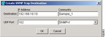
ステップ 4![]() Create SNMP Trap Destination ダイアログボックスで次の情報を入力します(図3-7)。
Create SNMP Trap Destination ダイアログボックスで次の情報を入力します(図3-7)。
•![]() Destination IP Address:ネットワーク管理システムの IP アドレスを入力します。ログインしているノードが ENE の場合は、送信先アドレスを GNE に設定します。
Destination IP Address:ネットワーク管理システムの IP アドレスを入力します。ログインしているノードが ENE の場合は、送信先アドレスを GNE に設定します。
•![]() Community:SNMP コミュニティ名を入力します。SNMP コミュニティ名については、『 Cisco ONS 15454 Troubleshooting Guide 』または『 Cisco ONS 15454 SDH Troubleshooting Guide 』を参照してください。
Community:SNMP コミュニティ名を入力します。SNMP コミュニティ名については、『 Cisco ONS 15454 Troubleshooting Guide 』または『 Cisco ONS 15454 SDH Troubleshooting Guide 』を参照してください。
(注) コミュニティ名は、アクセス制御と認証の形式です。ONS 15454 に割り当てるコミュニティ名は、大文字と小文字を区別し、Network Management System(NMS; ネットワーク管理システム)のコミュニティ名と一致させる必要があります。
•![]() UDP Port:SNMP のデフォルトの User Datagram Protocol(UDP)ポートは 162 です。ノードが SOCKS プロキシ サーバ ネットワークの ENE の場合、UDP ポートは GNE の SNMP リレー ポート(391)に設定する必要があります。
UDP Port:SNMP のデフォルトの User Datagram Protocol(UDP)ポートは 162 です。ノードが SOCKS プロキシ サーバ ネットワークの ENE の場合、UDP ポートは GNE の SNMP リレー ポート(391)に設定する必要があります。
•![]() Trap Version:SNMPv1 と SNMPv2 のいずれかを選択します。SNMPv1 と SNMPv2 のどちらを使用するかについては NMS のマニュアルを参照してください。
Trap Version:SNMPv1 と SNMPv2 のいずれかを選択します。SNMPv1 と SNMPv2 のどちらを使用するかについては NMS のマニュアルを参照してください。
ステップ 5![]() OK をクリックします。新しいトラップを設定したノードのノード IP アドレスが、Trap Destinations エリアに表示されます。
OK をクリックします。新しいトラップを設定したノードのノード IP アドレスが、Trap Destinations エリアに表示されます。
ステップ 6![]() Trap Destinations エリアに表示されたノード IP アドレスをクリックします。Selected Destination リストに表示される SNMP 情報を確認します。
Trap Destinations エリアに表示されたノード IP アドレスをクリックします。Selected Destination リストに表示される SNMP 情報を確認します。
ステップ 7![]() SNMP エージェントで特定の MIB に関する SNMP SET 要求を処理できるようにする場合は、 Allow SNMP Sets チェックボックスをオンにします。このボックスがオフの場合、SET 要求は拒否されます。
SNMP エージェントで特定の MIB に関する SNMP SET 要求を処理できるようにする場合は、 Allow SNMP Sets チェックボックスをオンにします。このボックスがオフの場合、SET 要求は拒否されます。
ステップ 8![]() SNMP プロキシ機能を設定し、ONS ファイアウォールを介してネットワーク管理、メッセージ レポーティング、パフォーマンス統計情報の取得を実行できるようにする場合は、SNMP タブにある Enable SNMP Proxy チェックボックスをオンにします。
SNMP プロキシ機能を設定し、ONS ファイアウォールを介してネットワーク管理、メッセージ レポーティング、パフォーマンス統計情報の取得を実行できるようにする場合は、SNMP タブにある Enable SNMP Proxy チェックボックスをオンにします。
(注) ONS ファイアウォール プロキシ機能は、ソフトウェア リリース 4.6 以降を実行しているノード上でのみ動作します。この機能を使用すると、ONS ファイアウォール越しに管理情報を交換できるようになります。
SNMP プロキシ機能の詳細については、『 Cisco ONS 15454 Troubleshooting Guide 』または『 Cisco ONS 15454 SDH Troubleshooting Guide 』を参照してください。
ステップ 10![]() SNMP プロキシを設定している場合、SNMP トラップのエラー数を NE に戻すための 3 つのリレーをトラップの各宛先アドレスに対して設定できます。
SNMP プロキシを設定している場合、SNMP トラップのエラー数を NE に戻すための 3 つのリレーをトラップの各宛先アドレスに対して設定できます。
a.![]() トラップの最初の送信先 IP アドレスをクリックします。Destination フィールドにアドレスとコミュニティ名が表示されます。
トラップの最初の送信先 IP アドレスをクリックします。Destination フィールドにアドレスとコミュニティ名が表示されます。
b.![]() Relay A、Relay B、および Relay C のフィールドに、SNMP プロキシの 3 つのリレー アドレスとコミュニティ名をそれぞれ入力します。
Relay A、Relay B、および Relay C のフィールドに、SNMP プロキシの 3 つのリレー アドレスとコミュニティ名をそれぞれ入力します。
(注) 各リレー ノードに指定するコミュニティ名は、NE で設定した SNMP コミュニティ名と一致させる必要があります。
(注) SNMP プロキシにより、SNMP トラップが、このノードから IpA、IpB、IpC を経由してトラップの送信先まで転送されます。この順番で正しく送信されるように、IP アドレスは正しい順番で入力してください。
ステップ 1![]() スロットを事前プロビジョニングするノードで「G46 CTC へのログイン」の作業を行います。すでにログインしている場合は、ステップ 2 に進みます。
スロットを事前プロビジョニングするノードで「G46 CTC へのログイン」の作業を行います。すでにログインしている場合は、ステップ 2 に進みます。
ステップ 2![]() Cisco MetroPlanner R2.5 がある場合は、このアプリケーションを起動して、ステップ 3 に進みます。Cisco MetroPlanner がない場合は、Cisco MetroPlanner R2.5 によって作成されたノード レイアウトのハード コピーを用意する必要があります。ノード レイアウトのハード コピーを用意できた場合は、ステップ 6 に進みます。Cisco MetroPlanner によって作成されたノード レイアウトが利用できない場合は、作業を中断してください。
Cisco MetroPlanner R2.5 がある場合は、このアプリケーションを起動して、ステップ 3 に進みます。Cisco MetroPlanner がない場合は、Cisco MetroPlanner R2.5 によって作成されたノード レイアウトのハード コピーを用意する必要があります。ノード レイアウトのハード コピーを用意できた場合は、ステップ 6 に進みます。Cisco MetroPlanner によって作成されたノード レイアウトが利用できない場合は、作業を中断してください。
ステップ 3![]() Cisco MetroPlanner で、設置に関するネットワーク計画をロードします(Cisco MetroPlanner の使用法については、『 Cisco MetroPlanner DWDM Operations Guide 』を参照してください)。
Cisco MetroPlanner で、設置に関するネットワーク計画をロードします(Cisco MetroPlanner の使用法については、『 Cisco MetroPlanner DWDM Operations Guide 』を参照してください)。
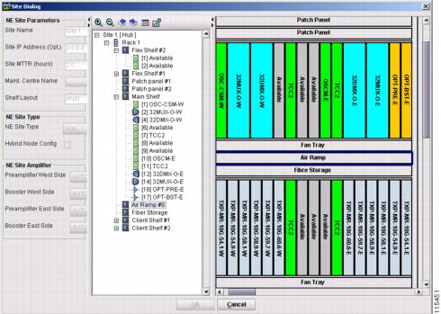
ステップ 4![]() Cisco MetroPlanner で、プロビジョニングするノードに関する Site Dialog ウィンドウを表示します。サイトの取り付け例を図3-8に示します。
Cisco MetroPlanner で、プロビジョニングするノードに関する Site Dialog ウィンドウを表示します。サイトの取り付け例を図3-8に示します。
図3-8 Cisco MetroPlanner Site Dialog ウィンドウ
ステップ 5![]() CTC と Cisco MetroPlanner のウィンドウを同時に見えるように配置します。
CTC と Cisco MetroPlanner のウィンドウを同時に見えるように配置します。
ステップ 6![]() CTC ノード ビュー内で、カードを取り付ける空のスロットを右クリックします。
CTC ノード ビュー内で、カードを取り付ける空のスロットを右クリックします。
ステップ 7![]() Add Card ポップアップ メニューから、Cisco MetroPlanner の Site Dialog ウィンドウを基にして取り付けるカードのタイプを選択します。Add Card ポップアップ メニューには、そのスロットに取り付けることができるカードだけが表示されます。
Add Card ポップアップ メニューから、Cisco MetroPlanner の Site Dialog ウィンドウを基にして取り付けるカードのタイプを選択します。Add Card ポップアップ メニューには、そのスロットに取り付けることができるカードだけが表示されます。
(注) スロットを事前プロビジョニングしておくと、カードがスロットに取り付けられた場合に、CTC シェルフ図にカードが白ではなく紫で表示されます。カード図に NP(not present、つまり存在しない)が表示されている場合は、当該カードが物理的に取り付けられていないことを示します。
ステップ 8![]() ステップ 7 の作業を繰り返して、Cisco MetroPlanner の Site Dialog ウィンドウに表示されているすべてのカードを CTC でプロビジョニングします。
ステップ 7 の作業を繰り返して、Cisco MetroPlanner の Site Dialog ウィンドウに表示されているすべてのカードを CTC でプロビジョニングします。

警告 作業中は、カードの ESD 破壊を防ぐため、必ず静電気防止用リスト ストラップを着用してください。感電する危険があるので、手や金属工具がバックプレーンに直接触れないようにしてください。
警告 「Laser Notice No. 50、2001 年 7 月 26 日付け」の変更を除いて、21 CFR 1040.10 および 1040.11 に適合しています。
警告 クラス 1(CDRH)およびクラス 1 M(IEC)のレーザー製品です。
警告 終端していないファイバ ケーブルの先端やコネクタからは、目に見えないレーザー光線が放射されていることがあります。光学機器は直接見ないでください。光学機器(ルーペ、拡大鏡、顕微鏡など)で 100 mm 以内から放射されるレーザーを見ると、目を痛める恐れがあります。
(注) カードのバックプレーン コネクタに保護クリップが装着されている場合は、カードを取り付ける前に、クリップを取り外してください。
(注) カードが正しく取り付けられなかった場合は、FAIL LED が連続して点滅します。
ステップ 1![]() 次のいずれかのソースを使用して、ノードのカード取り付け計画を表示します。
次のいずれかのソースを使用して、ノードのカード取り付け計画を表示します。
•![]() プロビジョニングするノードに関する Cisco MetroPlanner の Site Dialog ウィンドウ(図3-8)
プロビジョニングするノードに関する Cisco MetroPlanner の Site Dialog ウィンドウ(図3-8)
•![]() Cisco MetroPlanner の Site Dialog ウィンドウでプロビジョニングされたスロットの CTC ノード ビュー
Cisco MetroPlanner の Site Dialog ウィンドウでプロビジョニングされたスロットの CTC ノード ビュー
•![]() スロット計画を記述した文書。この計画は、Cisco MetroPlanner の Site Dialog ウィンドウの取り付け情報を基に作成する必要があります。
スロット計画を記述した文書。この計画は、Cisco MetroPlanner の Site Dialog ウィンドウの取り付け情報を基に作成する必要があります。
ステップ 2![]() カードの取り付けが、次の設置ガイドラインに適合していることを再度確認してください。
カードの取り付けが、次の設置ガイドラインに適合していることを再度確認してください。
•![]() OPT-BST:空いているイーストとウェストのペアのスロットのいずれにも取り付けることができますが、通常はスロット 1 と 17 に取り付けます。
OPT-BST:空いているイーストとウェストのペアのスロットのいずれにも取り付けることができますが、通常はスロット 1 と 17 に取り付けます。
•![]() OPT-PRE:空いているイーストとウェストのペアのスロットのいずれにも取り付けることができますが、通常はスロット 2 と 16 に取り付けます。
OPT-PRE:空いているイーストとウェストのペアのスロットのいずれにも取り付けることができますが、通常はスロット 2 と 16 に取り付けます。
•![]() OSC-CSM:空いているイーストとウェストのペアのスロットのいずれにも取り付けることができます。
OSC-CSM:空いているイーストとウェストのペアのスロットのいずれにも取り付けることができます。
•![]() 32MUX-O、32DMX-O、32DMX、32WSS:空いている 2 つのスロットに取り付け可能なダブルスロット カードです。
32MUX-O、32DMX-O、32DMX、32WSS:空いている 2 つのスロットに取り付け可能なダブルスロット カードです。
•![]() AD-xB-xx.x、AD-xC-xx.x、4MD-xx.x:空いているどのスロットにも取り付けることができます。
AD-xB-xx.x、AD-xC-xx.x、4MD-xx.x:空いているどのスロットにも取り付けることができます。
ステップ 3![]() パッケージから DWDM カードを取り出して、バックプレーン コネクタから保護キャップを取り外します。
パッケージから DWDM カードを取り出して、バックプレーン コネクタから保護キャップを取り外します。
ステップ 5![]() ラッチ/イジェクタを使用して、スロット ガイド レールに沿ってカードをしっかりとスライドさせ、スロットの後方のレセプタクルにカードを取り付けます。
ラッチ/イジェクタを使用して、スロット ガイド レールに沿ってカードをしっかりとスライドさせ、スロットの後方のレセプタクルにカードを取り付けます。
ステップ 6![]() カードが正しく挿入され、カードのラッチ/イジェクタが閉まっていることを確認します。
カードが正しく挿入され、カードのラッチ/イジェクタが閉まっていることを確認します。
(注) カードがバックプレーンに完全に装着されない状態でも、ラッチ/イジェクタが閉まることがあります。カードをそれ以上挿入できないことを確かめてください。
•![]() すべての LED が点灯したあと、5 秒以内に消灯します。
すべての LED が点灯したあと、5 秒以内に消灯します。
•![]() 新しいソフトウェアをカードにダウンロードしている場合は、ACT LED と SF LED が 20 秒から 3 分半、点滅します(時間はカードの種類によって異なります)。
新しいソフトウェアをカードにダウンロードしている場合は、ACT LED と SF LED が 20 秒から 3 分半、点滅します(時間はカードの種類によって異なります)。
•![]() 信号障害(SF)LED は、すべてのカード ポートがそれぞれの遠端の相手先に接続されて、信号が発生するまで点灯し続けます。
信号障害(SF)LED は、すべてのカード ポートがそれぞれの遠端の相手先に接続されて、信号が発生するまで点灯し続けます。
ステップ 8![]() カードが適切にブートされない場合、または LED アクティビティがステップ 7のとおりにならない場合は、次の点を調べてください。
カードが適切にブートされない場合、または LED アクティビティがステップ 7のとおりにならない場合は、次の点を調べてください。
•![]() 物理的なカード タイプが、CTC でそのスロット用にプロビジョニングされたカードのタイプに一致していない場合、カードがブートされない可能性があります。DWDM カードがブートされない場合、カードの欠陥であるとみなす前に、CTC を開けて、そのスロットが別のカード タイプ用にプロビジョニングされていないことを確認してください。
物理的なカード タイプが、CTC でそのスロット用にプロビジョニングされたカードのタイプに一致していない場合、カードがブートされない可能性があります。DWDM カードがブートされない場合、カードの欠陥であるとみなす前に、CTC を開けて、そのスロットが別のカード タイプ用にプロビジョニングされていないことを確認してください。
•![]() レッドの FAIL LED が点灯しない場合は、電源を調べてください。
レッドの FAIL LED が点灯しない場合は、電源を調べてください。
•![]() 別のカード用にプロビジョニングされたスロットにカードを挿入した場合、すべての LED が消灯します。
別のカード用にプロビジョニングされたスロットにカードを挿入した場合、すべての LED が消灯します。
•![]() レッドの FAIL LED が連続して点灯したり、LED の動作が異常な場合は、カードが取り付けられていません。カードを取り外して、ステップ 3 ~ 7 を繰り返してください。2 回めも正常に起動しない場合は、カードが壊れている可能性があります。次のレベルのサポートに問い合わせます。
レッドの FAIL LED が連続して点灯したり、LED の動作が異常な場合は、カードが取り付けられていません。カードを取り外して、ステップ 3 ~ 7 を繰り返してください。2 回めも正常に起動しない場合は、カードが壊れている可能性があります。次のレベルのサポートに問い合わせます。
(注) DWDM ノード タイプは、取り付けたカードで決まります。たとえば、2 枚の 32DMX-O カードと 2 枚の 32MUX-O カードを取り付けて、AD-xC カードまたは AD-xB カードを取り付けていないノードは、CTC によってハブ ノードと見なされます。ただし、1 枚の 32DMX-O カードと 1 枚の 32MUX-O カードを取り付けて、AD-xC カードまたは AD-xB カードを取り付けていないノードは、CTC によって終端ノードと見なされます。詳細については、第 16 章「カード リファレンス」を参照してください。
ステップ 9![]() 3 ~ 8 のステップを
3 ~ 8 のステップを![]() 繰り返して、すべての DWDM カードをノードに取り付けます。
繰り返して、すべての DWDM カードをノードに取り付けます。
ステップ 10![]() OPT-PRE カードを取り付ける場合は、MetroPlanner のサイト計画を基に次のいずれかの作業を行います。OPT-PRE を取り付けない場合は、ステップ 11 に進みます。
OPT-PRE カードを取り付ける場合は、MetroPlanner のサイト計画を基に次のいずれかの作業を行います。OPT-PRE を取り付けない場合は、ステップ 11 に進みます。
•![]() サイト計画に DCU が含まれる場合は、「G31 DWDM 分散補償ユニットの取り付け」 の作業を行います。
サイト計画に DCU が含まれる場合は、「G31 DWDM 分散補償ユニットの取り付け」 の作業を行います。
•![]() サイト計画に DCU が含まれない場合は、OPT-PRE DC の TX ポートと RX ポートの間に、+1~-1 dB の許容範囲を持つ 4 dB の減衰器を取り付けます。
サイト計画に DCU が含まれない場合は、OPT-PRE DC の TX ポートと RX ポートの間に、+1~-1 dB の許容範囲を持つ 4 dB の減衰器を取り付けます。
ステップ 11![]() 「G32 トランスポンダ カードおよびマックスポンダ カードの取り付け」に進みます。
「G32 トランスポンダ カードおよびマックスポンダ カードの取り付け」に進みます。
この手順では、DWDM シェルフ用の分散補償ユニット(DCU-xx.x)の取り付け方法を説明します。これは、OPT-PRE カードを取り付ける場合に必要です。 |
|
警告 「Laser Notice No. 50、2001 年 7 月 26 日付け」の変更を除いて、21 CFR 1040.10 および 1040.11 に適合しています。
警告 クラス 1(CDRH)およびクラス 1 M(IEC)のレーザー製品です。
警告 終端していないファイバ ケーブルの先端やコネクタからは、目に見えないレーザー光線が放射されていることがあります。光学機器は直接見ないでください。光学機器(ルーペ、拡大鏡、顕微鏡など)で 100 mm 以内から放射されるレーザーを見ると、目を痛める恐れがあります。
(注) DCU のバックプレーン コネクタに保護クリップが装着されている場合は、ユニットを取り付ける前に、クリップを取り外してください。
(注) DCU が取り付けられていないで、OPT-PRE カードが取り付けられている場合は、OPT-PRE DC の TX ポートと RX ポートの間に 5 dB の減衰器を挿入します。
ステップ 2![]() ガイド レールに沿って DCU をしっかりとスライドさせ、シェルフの最上部の水平な分散補償カード スロットの後方のレセプタクルに DCU カードを取り付けます。
ガイド レールに沿って DCU をしっかりとスライドさせ、シェルフの最上部の水平な分散補償カード スロットの後方のレセプタクルに DCU カードを取り付けます。
(注) ウェスト DCU は通常左側に取り付けられ、イースト DCU は通常右側に取り付けられます。
(注) スロットに誤った DCU を取り付けた場合は、その DCU を取り外して正しい DCU を取り付けてください。
(注) DCU がバックプレーンに完全に装着されない状態で、ラッチが閉まることがあります。DCU をそれ以上挿入できないことを確かめてください。
ステップ 4![]() DCU のハンドルをつかみ、そっと引いてみて、カードがバックプレーンに固定されていることを確認します。カードが動かなければ、取り付けは完全です。カードが動く場合は、 2 と 3 を繰り返します。
DCU のハンドルをつかみ、そっと引いてみて、カードがバックプレーンに固定されていることを確認します。カードが動かなければ、取り付けは完全です。カードが動く場合は、 2 と 3 を繰り返します。
ステップ 5![]() 「G32 トランスポンダ カードおよびマックスポンダ カードの取り付け」に進みます。
「G32 トランスポンダ カードおよびマックスポンダ カードの取り付け」に進みます。
NTP-G32 トランスポンダ カードおよびマックスポンダ カードの取り付け
この手順では、ONS 15454 のトランスポンダ(TXP)カードとマックスポンダ(MXP)カードの取り付け、およびファイバの接続方法を説明します。 |
|
TXP_MR_10G、TXP_MR_10E、TXP_MR_2.5G、TXPP_MR_2.5G、MXP_2.5G_10G、MXP_2.5G_10E、MXP_MR_2.5G、MXPP_MR_2.5G カード(該当する場合) |
|
警告 作業中は、カードの ESD 破壊を防ぐため、必ず静電気防止用リスト ストラップを着用してください。感電する危険があるので、手や金属工具がバックプレーンに直接触れないようにしてください。
警告 「Laser Notice No. 50、2001 年 7 月 26 日付け」の変更を除いて、21 CFR 1040.10 および 1040.11 に適合しています。
警告 終端していないファイバ ケーブルの先端やコネクタからは、目に見えないレーザー光線が放射されていることがあります。光学機器は直接見ないでください。光学機器(ルーペ、拡大鏡、顕微鏡など)で 100 mm 以内から放射されるレーザーを見ると、目を痛める恐れがあります。
(注) カードのバックプレーン コネクタに保護クリップが装着されている場合は、カードを取り付ける前に、クリップを取り外してください。
(注) カードが正しく取り付けられなかった場合は、FAIL LED が連続して点滅します。
ステップ 1![]() 次のいずれかのソースを使用して、ノードのカード取り付け計画を表示します。
次のいずれかのソースを使用して、ノードのカード取り付け計画を表示します。
•![]() プロビジョニングするノードに関する Cisco MetroPlanner の Site Dialog ウィンドウ
プロビジョニングするノードに関する Cisco MetroPlanner の Site Dialog ウィンドウ
•![]() Cisco MetroPlanner の Site Dialog ウィンドウでプロビジョニングされたスロットの CTC ノード ビュー
Cisco MetroPlanner の Site Dialog ウィンドウでプロビジョニングされたスロットの CTC ノード ビュー
•![]() スロット計画を記述した文書。この計画は、Cisco MetroPlanner の Site Dialog ウィンドウの取り付け情報を基に作成する必要があります。
スロット計画を記述した文書。この計画は、Cisco MetroPlanner の Site Dialog ウィンドウの取り付け情報を基に作成する必要があります。
ステップ 2![]() パッケージから TXP または MXP カードを取り出して、バックプレーン コネクタから保護クリップを取り外します。
パッケージから TXP または MXP カードを取り出して、バックプレーン コネクタから保護クリップを取り外します。
ステップ 4![]() ラッチ/イジェクタを使用して、ガイド レールに沿って TXP または MXP カードをしっかりとスライドさせ、スロットの後ろのレセプタクルにカードを取り付けます。
ラッチ/イジェクタを使用して、ガイド レールに沿って TXP または MXP カードをしっかりとスライドさせ、スロットの後ろのレセプタクルにカードを取り付けます。
(注) スロットに誤ったカードを取り付けた場合は、「G107 DWDM カードの取り外しおよび交換」を行ってください。
ステップ 5![]() カードが正しく挿入され、カードのラッチ/イジェクタが閉まっていることを確認します。
カードが正しく挿入され、カードのラッチ/イジェクタが閉まっていることを確認します。
(注) カードがバックプレーンに完全に装着されない状態でも、ラッチ/イジェクタが閉まることがあります。カードをそれ以上挿入できないことを確かめてください。
•![]() レッドの FAIL LED が 20~30 秒間点灯します。
レッドの FAIL LED が 20~30 秒間点灯します。
•![]() レッドの FAIL LED が 35~45 秒間点滅します。
レッドの FAIL LED が 35~45 秒間点滅します。
•![]() すべての LED が一度点滅してから、5~10 秒間消灯します。
すべての LED が一度点滅してから、5~10 秒間消灯します。
•![]() ACT または ACT/STBY LED が点灯します。すべてのカード ポートが遠端の相手先に接続し、信号が発生するまで、SF LED が点灯したままになることがあります。
ACT または ACT/STBY LED が点灯します。すべてのカード ポートが遠端の相手先に接続し、信号が発生するまで、SF LED が点灯したままになることがあります。
ステップ 7![]() カードが適切にブートされない場合、または LED アクティビティがステップ 6のとおりにならない場合は、次の点を調べてください。
カードが適切にブートされない場合、または LED アクティビティがステップ 6のとおりにならない場合は、次の点を調べてください。
•![]() 物理的なカード タイプが、CTC でそのスロット用にプロビジョニングされたカードのタイプに一致していない場合、カードがブートされない可能性があります。TXP または MXP カードがブートされない場合、カードの欠陥であるとみなす前に、CTC を開けて、そのスロットが別のカード タイプ用にプロビジョニングされていないことを確認してください。
物理的なカード タイプが、CTC でそのスロット用にプロビジョニングされたカードのタイプに一致していない場合、カードがブートされない可能性があります。TXP または MXP カードがブートされない場合、カードの欠陥であるとみなす前に、CTC を開けて、そのスロットが別のカード タイプ用にプロビジョニングされていないことを確認してください。
•![]() レッドの FAIL LED が点灯しない場合は、電源を調べてください。
レッドの FAIL LED が点灯しない場合は、電源を調べてください。
•![]() 別のカード用にプロビジョニングされたスロットにカードを挿入した場合、すべての LED が消灯します。
別のカード用にプロビジョニングされたスロットにカードを挿入した場合、すべての LED が消灯します。
•![]() レッドの FAIL LED が連続して点灯したり、LED の動作が異常な場合は、カードが正しく取り付けられていません。カードを取り外して、ステップ 3 ~ 6 を繰り返してください。
レッドの FAIL LED が連続して点灯したり、LED の動作が異常な場合は、カードが正しく取り付けられていません。カードを取り外して、ステップ 3 ~ 6 を繰り返してください。
ステップ 8![]() TXP または MXP に Small-Form Pluggable(SFP または XFP)コネクタが必要な場合、次のどちらかの作業を実行してください。
TXP または MXP に Small-Form Pluggable(SFP または XFP)コネクタが必要な場合、次のどちらかの作業を実行してください。
•![]() 「G63 SFP または XFP の取り付け」:この作業を実行して、SFP、XFP を TXP または MXP に物理的に取り付けます。
「G63 SFP または XFP の取り付け」:この作業を実行して、SFP、XFP を TXP または MXP に物理的に取り付けます。
•![]() 「G273 SFP または XFP スロットの事前プロビジョニング」:(任意)SFP や XFP を所有していない場合に SFP や XFP スロットを事前プロビジョニングするには、この作業を実行します。マルチレート SFP または XFP を事前プロビジョニングするには、「G278 光回線レートのプロビジョニング」を実行します。
「G273 SFP または XFP スロットの事前プロビジョニング」:(任意)SFP や XFP を所有していない場合に SFP や XFP スロットを事前プロビジョニングするには、この作業を実行します。マルチレート SFP または XFP を事前プロビジョニングするには、「G278 光回線レートのプロビジョニング」を実行します。
(注) PPM は第 5 章「トランスポンダ カードおよびマックスポンダ カードのプロビジョニング」でプロビジョニングされます。
ステップ 9![]() SFP または XFP を取り外すには、「G64 SFP または XFP の取り外し」を実行します。
SFP または XFP を取り外すには、「G64 SFP または XFP の取り外し」を実行します。
(注) すべてのノードのターンアップ手順を完了したら、TXP および MXP カードをプロビジョニングします。TXP および MXP のプロビジョニング手順は第 5 章「トランスポンダ カードおよびマックスポンダ カードのプロビジョニング」で説明されています。
DLP-G273 SFP または XFP スロットの事前プロビジョニング
この手順では、TXP カードおよび MXP カードに光ファイバを接続する SFP/XFP をプロビジョニングします。SFP/XFP は CTC では Pluggable Port Modules(PPM)と呼ばれています。 |
|
ステップ 1![]() 「G46 CTC へのログイン」の作業を行い、ネットワーク上の ONS 15454 にログインします。
「G46 CTC へのログイン」の作業を行い、ネットワーク上の ONS 15454 にログインします。
a.![]() アラーム フィルタ機能がディセーブルであることを確認します。必要に応じて、「G128 アラーム フィルタのディセーブル化」を参照してください。
アラーム フィルタ機能がディセーブルであることを確認します。必要に応じて、「G128 アラーム フィルタのディセーブル化」を参照してください。
b.![]() 説明のつかない状態がネットワーク上に表示されていないことを確認します。説明のつかない状態が表示されている場合は、作業を進める前に解決してください。『 Cisco ONS 15454 Troubleshooting Guide 』または『 Cisco ONS 15454 SDH Troubleshooting Guide 』を参照してください。
説明のつかない状態がネットワーク上に表示されていないことを確認します。説明のつかない状態が表示されている場合は、作業を進める前に解決してください。『 Cisco ONS 15454 Troubleshooting Guide 』または『 Cisco ONS 15454 SDH Troubleshooting Guide 』を参照してください。
c.![]() 「G114 CTC データのエクスポート」の作業を行い、アラームと状態情報をエクスポートします。
「G114 CTC データのエクスポート」の作業を行い、アラームと状態情報をエクスポートします。
ステップ 3![]() ノード ビューで、PPM 設定をプロビジョニングする TXP カードまたは MXP カードをダブルクリックします。
ノード ビューで、PPM 設定をプロビジョニングする TXP カードまたは MXP カードをダブルクリックします。
ステップ 4![]() Provisioning > Pluggable Port Modules のタブをクリックします。
Provisioning > Pluggable Port Modules のタブをクリックします。
ステップ 5![]() Pluggable Port Module ペインにある Create をクリックします。Create PPM ダイアログボックスが表示されます。
Pluggable Port Module ペインにある Create をクリックします。Create PPM ダイアログボックスが表示されます。
ステップ 6![]() Create PPM ダイアログボックスで次の情報を入力します。
Create PPM ダイアログボックスで次の情報を入力します。
•![]() PPM:SFP/XFP を装着しているスロットの番号をドロップダウン リストからクリックします。
PPM:SFP/XFP を装着しているスロットの番号をドロップダウン リストからクリックします。
•![]() PPM Type:SFP/XFP がサポートしているポートの番号をドロップダウン リストからクリックします。1 つのポートだけがサポートされる場合、PPM (1 port) が唯一のメニュー オプションです。
PPM Type:SFP/XFP がサポートしているポートの番号をドロップダウン リストからクリックします。1 つのポートだけがサポートされる場合、PPM (1 port) が唯一のメニュー オプションです。
ステップ 7![]() OK をクリックします。新しく作成されたポートが Pluggable Port Modules ペインに表示されます。SFP/XFP が実際に取り付けられるまでは、Pluggable Port Modules ペインの行がライトブルーで表示され、Actual Equipment Type カラムには事前プロビジョニングされた PPM が不明と表示されます。SFP/XFP が取り付けられると、ペインの行がホワイトに変わり、Actual Equipment Type カラムには機器名が表示されます。
OK をクリックします。新しく作成されたポートが Pluggable Port Modules ペインに表示されます。SFP/XFP が実際に取り付けられるまでは、Pluggable Port Modules ペインの行がライトブルーで表示され、Actual Equipment Type カラムには事前プロビジョニングされた PPM が不明と表示されます。SFP/XFP が取り付けられると、ペインの行がホワイトに変わり、Actual Equipment Type カラムには機器名が表示されます。
ステップ 8![]() Pluggable Port Modules ペインのリストに PPM が表示されていることを確認します。表示されない場合は、 5 ~ 7 のステップを
Pluggable Port Modules ペインのリストに PPM が表示されていることを確認します。表示されない場合は、 5 ~ 7 のステップを![]() 繰り返します。
繰り返します。
ステップ 9![]() 作業を繰り返して、2 つめの PPM をプロビジョニングします。
作業を繰り返して、2 つめの PPM をプロビジョニングします。
この作業では、TXP および MXP カードに SFP または XFP を取り付けます。SFP/XFP には、光ファイバ インターフェイスが搭載されています。 |
|
(注) CTC では、SFP および XFP を一般に Pluggable-Port Modules(PPM; 着脱可能ポートモジュール)と呼びます。SFP/XFP の取り付け終了後、マルチレート PPM(OC-3 または OC-12 の回線レートを提供する PPM)を CTC でプロビジョニングする必要があります。「G277 マルチレート PPM のプロビジョニング」を参照してください。
ステップ 1![]() ネットワークと TXP または MXP カードに対して適正な SFP が使用されていることを確認します( SFP/XFP とカードの互換性を参照)。取り付ける SFP 同士に互換性がある(SX と SX、LX/LX と LX/LX など)ことを確認します。
ネットワークと TXP または MXP カードに対して適正な SFP が使用されていることを確認します( SFP/XFP とカードの互換性を参照)。取り付ける SFP 同士に互換性がある(SX と SX、LX/LX と LX/LX など)ことを確認します。
•![]() マイラー タブ SFP/XFP では、SFP/XFP をスロットにスライドさせます。
マイラー タブ SFP/XFP では、SFP/XFP をスロットにスライドさせます。
•![]() アクチュエータ/ボタン SFP/XFP では、カチッという音がするまで SFP/XFP をスロット内へスライドさせます。
アクチュエータ/ボタン SFP/XFP では、カチッという音がするまで SFP/XFP をスロット内へスライドさせます。
•![]() ベイル クラスプ SFP/XFP では、スロットに挿入する前にベイル クラスプをラッチしてから(上向きに閉じて)、スロットにスライドします。
ベイル クラスプ SFP/XFP では、スロットに挿入する前にベイル クラスプをラッチしてから(上向きに閉じて)、スロットにスライドします。
(注) SFP/XFP は誤って取り付けられないようにキー付きになっています。
ステップ 3![]() ネットワーク光ファイバ ケーブルを取り付ける準備ができるまで、SFP/XFP から保護キャップを取り外さないようにしてください。
ネットワーク光ファイバ ケーブルを取り付ける準備ができるまで、SFP/XFP から保護キャップを取り外さないようにしてください。
(注) この作業では SFP/XFP ハードウェアを取り外します。SFP/XFP のプロビジョニングを削除するには、「G280 PPM の削除」を参照してください。
ステップ 1![]() GBIC SC タイプのコネクタまたは SFP/XFP LC タイプのコネクタから、ネットワーク光ファイバ ケーブルを接続解除します。
GBIC SC タイプのコネクタまたは SFP/XFP LC タイプのコネクタから、ネットワーク光ファイバ ケーブルを接続解除します。
ステップ 2![]() 次のいずれかの作業(SFP/XFP のラッチの種類によって異なります)を行って、スロットから SFP/XFP を取り外します。
次のいずれかの作業(SFP/XFP のラッチの種類によって異なります)を行って、スロットから SFP/XFP を取り外します。
•![]() マイラー タブ SFP/XFP では、マイラー タブを引き出します。
マイラー タブ SFP/XFP では、マイラー タブを引き出します。
•![]() アクチュエータ/ボタン SFP/XFP では、アクチュエータ/ボタンを押します。
アクチュエータ/ボタン SFP/XFP では、アクチュエータ/ボタンを押します。
•![]() ベイル クラスプ SFP/XFP では、ベイル クラスプのラッチを解除し、下方に下げます。
ベイル クラスプ SFP/XFP では、ベイル クラスプのラッチを解除し、下方に下げます。
ステップ 3![]() カードをスライドさせてスロットから取り出します。
カードをスライドさせてスロットから取り出します。
この手順では、未使用のトラフィック スロットまたは AIC-I カード スロット(スロット 1~6、スロット 9、およびスロット 11~17)にフィラー カード(ブランクの前面プレート)を取り付ける方法について説明します。フィラー カードを使用すると、適切な通気と EMI 要件を維持できます。 |
|
警告 ブランクの前面プレート(フィラー パネル)には、3 つの重要な役割があります。シャーシ内の危険な電圧および電流による感電を防ぐこと、他の装置への EMI(電磁波干渉)の影響を防ぐこと、およびシャーシ内の空気の流れを適切な状態に保つことです。必ずすべてのカードおよび前面プレートを正しく取り付けた状態で、システムを運用してください。
(注) 今後のソフトウェア リリースでは、ONS 15454 の管理インターフェイスによってこのカードを検出できるようになります。
ステップ 2![]() カードをガイド レールに沿ってスライドさせ、スロットに取り付けます。
カードをガイド レールに沿ってスライドさせ、スロットに取り付けます。
ステップ 4![]() 残りの使用していないカード スロットについても、同様の作業を繰り返します。
残りの使用していないカード スロットについても、同様の作業を繰り返します。
ステップ 5![]() 「G33 Y 字型ケーブル保護グループの作成」に進みます。
「G33 Y 字型ケーブル保護グループの作成」に進みます。
この作業では、2 枚のトランスポンダ カード(TXP_MR_10G、 |
|
(注) ポートが Y 字型ケーブル保護グループにない場合、Loss of Pointer Path(LOP-P; パス ポインタ異常)がスプリット信号に発生する可能性があります。
ステップ 1![]() サイトのトラフィック マトリクス テーブルを Cisco MetroPlanner で開きます(または印刷コピーを参照)。Y 字型ケーブル保護グループが必要な TXP または MXP カードを確認します(Y 字型ケーブル保護が必要なカードは、Traffic Matrix テーブルの Protection Type カラムに「Y-Cable」と表示されます。詳細については、『 Cisco MetroPlanner DWDM Operations Guide 』を参照してください)。
サイトのトラフィック マトリクス テーブルを Cisco MetroPlanner で開きます(または印刷コピーを参照)。Y 字型ケーブル保護グループが必要な TXP または MXP カードを確認します(Y 字型ケーブル保護が必要なカードは、Traffic Matrix テーブルの Protection Type カラムに「Y-Cable」と表示されます。詳細については、『 Cisco MetroPlanner DWDM Operations Guide 』を参照してください)。
ステップ 2![]() TXP カードまたは MXP カードが、 表3-2 で指定された要件に従って取り付けられていることを確認します。この表は、DWDM クライアント カード用の ONS 15454 で利用可能な保護タイプを表しています。
TXP カードまたは MXP カードが、 表3-2 で指定された要件に従って取り付けられていることを確認します。この表は、DWDM クライアント カード用の ONS 15454 で利用可能な保護タイプを表しています。
(注) Y 字型ケーブル保護の必要な TXP カードまたは MXP カードは、Cisco MetroPlanner のトラフィック マトリクス テーブルで確認できます。Y 字型ケーブル保護が必要なカードは、テーブルの Protection Type カラムに「Y-Cable」と表示されます。詳細については、『Cisco MetroPlanner DWDM Operations Guide』を参照してください。
ステップ 3![]() プロビジョニングするネットワークのトラフィック マトリクス テーブルに移動して、Cisco MetroPlanner のトラフィック マトリクス テーブルを確認します。
プロビジョニングするネットワークのトラフィック マトリクス テーブルに移動して、Cisco MetroPlanner のトラフィック マトリクス テーブルを確認します。
ステップ 4![]() PPM のペイロードとペイロード レートが、Y 字型ケーブル保護グループ作成対象の TXP カードまたは MXP カードと同じになるようにプロビジョニングされていることを確認します。次のいずれかの方法を使用できます。
PPM のペイロードとペイロード レートが、Y 字型ケーブル保護グループ作成対象の TXP カードまたは MXP カードと同じになるようにプロビジョニングされていることを確認します。次のいずれかの方法を使用できます。
•![]() ノード ビューで、TXP または MXP クライアント ポート上にマウスを動かします。PPM がプロビジョニングされている場合、2 つのドットがポート図に表示され、マウスをポート上に動かすと、PPM のペイロードとレートが表示されます。
ノード ビューで、TXP または MXP クライアント ポート上にマウスを動かします。PPM がプロビジョニングされている場合、2 つのドットがポート図に表示され、マウスをポート上に動かすと、PPM のペイロードとレートが表示されます。
•![]() TXP カードまたは MXP カードをカードビューで表示します。 Provisioning > Pluggable Port Module タブをクリックします。Pluggable Port Module エリアで PPM が プロビジョニングされていること、および Selected PPM エリアでペイロードのタイプとレートが PPM に対してプロビジョニングされていることを確認します。
TXP カードまたは MXP カードをカードビューで表示します。 Provisioning > Pluggable Port Module タブをクリックします。Pluggable Port Module エリアで PPM が プロビジョニングされていること、および Selected PPM エリアでペイロードのタイプとレートが PPM に対してプロビジョニングされていることを確認します。
PPM のペイロードとペイロード レートは、TXP カードまたは MXP カードと同じにする必要があります。
ステップ 5![]() ノード ビューで、 Provisioning > Protection タブをクリックします。
ノード ビューで、 Provisioning > Protection タブをクリックします。
ステップ 6![]() Protection Groups エリアで、 Create をクリックします。
Protection Groups エリアで、 Create をクリックします。
ステップ 7![]() Create Protection Group ダイアログボックスで次の情報を入力します。
Create Protection Group ダイアログボックスで次の情報を入力します。
•![]() Name:保護グループの名前を入力します。保護グループ名には、32 字までの英数字(a~z、A~Z、0~9)を使用します。特殊文字も使用できますが、TL1 と互換性を持たせるために、疑問符(?)、バックスラッシュ(\)、二重引用符(")は使用しないでください。
Name:保護グループの名前を入力します。保護グループ名には、32 字までの英数字(a~z、A~Z、0~9)を使用します。特殊文字も使用できますが、TL1 と互換性を持たせるために、疑問符(?)、バックスラッシュ(\)、二重引用符(")は使用しないでください。
•![]() Type:ドロップダウン リストから Y Cable を選択します。
Type:ドロップダウン リストから Y Cable を選択します。
•![]() Protect Port:ドロップダウン リストから保護ポートを選択します。ドロップダウン メニューには、使用可能なトランスポンダ ポートまたはマックスポンダ ポートが表示されます。トランスポンダ カードまたはマックスポンダ カードが取り付けられていない場合は、ドロップダウン リストにポートは表示されません。
Protect Port:ドロップダウン リストから保護ポートを選択します。ドロップダウン メニューには、使用可能なトランスポンダ ポートまたはマックスポンダ ポートが表示されます。トランスポンダ カードまたはマックスポンダ カードが取り付けられていない場合は、ドロップダウン リストにポートは表示されません。
保護ポートを選択すると、保護に使用できるポートのリストが Available Ports リストに表示されます(図3-9 参照)。使用可能なカードがない場合は、ポートは表示されません。その場合は、この作業を行う前に、物理カードを取り付けるか、「G29 スロットの事前プロビジョニング」の作業を行って ONS 15454 スロットを事前にプロビジョニングする必要があります。
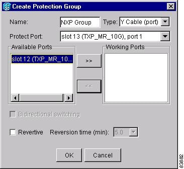
ステップ 8![]() Available Ports リストから、Protect Port で選択したポートで保護するポートを選択します。上にある矢印ボタンをクリックして、各ポートを Working Ports リストに移動します。
Available Ports リストから、Protect Port で選択したポートで保護するポートを選択します。上にある矢印ボタンをクリックして、各ポートを Working Ports リストに移動します。
•![]() Revertive:障害状態が修正されたあと Reversion Time フィールドに入力された時間でトラフィックを現用ポートに復帰させる場合、このボックスをオンにします。
Revertive:障害状態が修正されたあと Reversion Time フィールドに入力された時間でトラフィックを現用ポートに復帰させる場合、このボックスをオンにします。
•![]() Reversion time:Revertive をオンにした場合に、ドロップダウン リストから復元時間を選択します。範囲は 0.5~12.0 分です。デフォルトは 5.0 分です。復元時間は、トラフィックが現用カードに復帰するまでの時間です。切り替えの原因になった条件がなくなると、復元タイマーが開始します。
Reversion time:Revertive をオンにした場合に、ドロップダウン リストから復元時間を選択します。範囲は 0.5~12.0 分です。デフォルトは 5.0 分です。復元時間は、トラフィックが現用カードに復帰するまでの時間です。切り替えの原因になった条件がなくなると、復元タイマーが開始します。
NTP-G34 DWDM カードへの光ファイバ ケーブルの取り付け
| 「G31 DWDM 分散補償ユニットの取り付け」(該当する場合) |
|
警告 「Laser Notice No. 50、2001 年 7 月 26 日付け」の変更を除いて、21 CFR 1040.10 および 1040.11 に適合しています。
警告 クラス 1(CDRH)およびクラス 1 M(IEC)のレーザー製品です。
(注) この手順では、イーストからウェスト方向、またはウェストからイースト方向のパターンでファイバを接続するのが一般的です。「ウェスト」とはスロット 1、2、3、4、5、6、および 8 のカードとポートを、「イースト」とはスロット 10、12、13、14、15、16、および 17 のカードとポートをそれぞれ表しています。
ステップ 1![]() Cisco MetroPlanner でサイト計画を表示するか、または MetroPlanner の内部接続テーブルの印刷コピーを参照します。Cisco MetroPlanner については、『 Cisco MetroPlanner DWDM Operations Guide 』を参照してください。
Cisco MetroPlanner でサイト計画を表示するか、または MetroPlanner の内部接続テーブルの印刷コピーを参照します。Cisco MetroPlanner については、『 Cisco MetroPlanner DWDM Operations Guide 』を参照してください。
ステップ 2![]() プロビジョニングするノードの内部接続テーブルに移動します(図3-10)。内部接続テーブルでは、エンドポイントの接続が必要なパッチ コードを確認できます。Position 1 はファイバのスタート ポイントを、Position 2 はファイバのエンドポイントをそれぞれ示します。パッチ コードのエンドポイントは、サイト、スロット、およびポートによって識別されます。Cisco MetroPlanner の内部接続テーブルでは、次の情報が提供されます。
プロビジョニングするノードの内部接続テーブルに移動します(図3-10)。内部接続テーブルでは、エンドポイントの接続が必要なパッチ コードを確認できます。Position 1 はファイバのスタート ポイントを、Position 2 はファイバのエンドポイントをそれぞれ示します。パッチ コードのエンドポイントは、サイト、スロット、およびポートによって識別されます。Cisco MetroPlanner の内部接続テーブルでは、次の情報が提供されます。
•![]() Site:内部接続をプロビジョニングするノードの DWDM ネットワーク サイト番号
Site:内部接続をプロビジョニングするノードの DWDM ネットワーク サイト番号
•![]() Position-1:最初の位置ラック、シェルフ、およびスロット。たとえば、Rack#1.Main Shelf.02 は、Rack #1 の Main Shelf にある Slot 2 を示しています。ラック名、シェルフ名、位置に関しては、Cisco MetroPlanner Site Dialog ウィンドウを参照してください。
Position-1:最初の位置ラック、シェルフ、およびスロット。たとえば、Rack#1.Main Shelf.02 は、Rack #1 の Main Shelf にある Slot 2 を示しています。ラック名、シェルフ名、位置に関しては、Cisco MetroPlanner Site Dialog ウィンドウを参照してください。
•![]() Unit-1:最初の位置のスロットに取り付けられている ONS 15454 DWDM カード(ユニット)
Unit-1:最初の位置のスロットに取り付けられている ONS 15454 DWDM カード(ユニット)
•![]() Port#-1:CTC に表示される最初の Position-1 の接続のポート識別子
Port#-1:CTC に表示される最初の Position-1 の接続のポート識別子
•![]() Port ID-1:TL1 に表示される Position-1 の接続のポート識別子
Port ID-1:TL1 に表示される Position-1 の接続のポート識別子
•![]() Port Label-1:カードのフロント プレートに印字された物理ポートの名称。CTC カード ビューで、Position-1 の接続に対して表示されます。
Port Label-1:カードのフロント プレートに印字された物理ポートの名称。CTC カード ビューで、Position-1 の接続に対して表示されます。
•![]() Patchcord Type:必要に応じて、要求される減衰レベルを示します。
Patchcord Type:必要に応じて、要求される減衰レベルを示します。
•![]() Position-2:2 番めの位置ラック、シェルフ、およびスロット。たとえば、Rack#1.Main Shelf.02 は、Rack #1 の Main Shelf にある Slot 2 を示しています。ラック名、シェルフ名、位置に関しては、Cisco MetroPlanner Site Dialog ウィンドウを参照してください。
Position-2:2 番めの位置ラック、シェルフ、およびスロット。たとえば、Rack#1.Main Shelf.02 は、Rack #1 の Main Shelf にある Slot 2 を示しています。ラック名、シェルフ名、位置に関しては、Cisco MetroPlanner Site Dialog ウィンドウを参照してください。
•![]() Unit-2:Position-2 のスロットに取り付けられている ONS 15454 DWDM カード(ユニット)。
Unit-2:Position-2 のスロットに取り付けられている ONS 15454 DWDM カード(ユニット)。
•![]() Port#2:CTC に表示される最初の Position-2 の接続のポート識別子
Port#2:CTC に表示される最初の Position-2 の接続のポート識別子
•![]() Port ID-2:TL1 に表示される Position-2 の接続のポート識別子
Port ID-2:TL1 に表示される Position-2 の接続のポート識別子
•![]() Port Label-2:カードのフロント プレートに印字された物理ポートの名称。CTC カード ビューで、Position-2 の接続に対して表示されます。
Port Label-2:カードのフロント プレートに印字された物理ポートの名称。CTC カード ビューで、Position-2 の接続に対して表示されます。
•![]() Manually Set:CTC で手作業で接続を作成する必要があるか否かを示します。このカラムに Yes が表示されている場合、接続を手作業で作成する必要があります。
Manually Set:CTC で手作業で接続を作成する必要があるか否かを示します。このカラムに Yes が表示されている場合、接続を手作業で作成する必要があります。
図3-10 Cisco MetroPlanner 内部接続テーブル
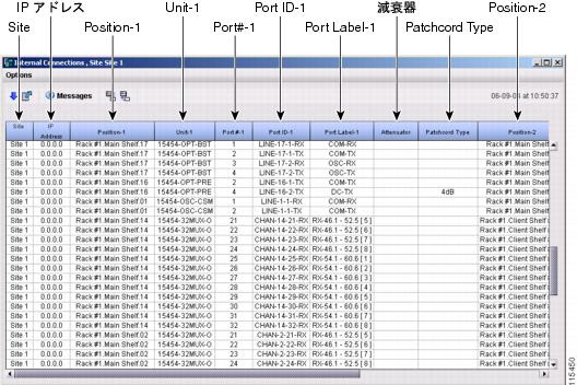
b.![]() Save Table ダイアログボックスの File Name フィールドにファイル名を入力します。
Save Table ダイアログボックスの File Name フィールドにファイル名を入力します。
c.![]() Files of Type フィールドで、 HTML (Web ブラウザで閲覧可能な HTML ファイルとして保存されます)、または Tab Separated Values(スプレッドシート アプリケーションにインポート可能なタブ切りテキスト ファイルとして保存されます)を選択します。
Files of Type フィールドで、 HTML (Web ブラウザで閲覧可能な HTML ファイルとして保存されます)、または Tab Separated Values(スプレッドシート アプリケーションにインポート可能なタブ切りテキスト ファイルとして保存されます)を選択します。
ステップ 4![]() エクスポートした MetroPlanner の内部接続ファイルを Web ブラウザ(またはスプレッドシート アプリケーション)で開いて印刷します。
エクスポートした MetroPlanner の内部接続ファイルを Web ブラウザ(またはスプレッドシート アプリケーション)で開いて印刷します。
ステップ 5![]() Cisco MetroPlanner の内部接続テーブルに表示される接続を確立するために必要なファイバが利用可能であることを確認します。
Cisco MetroPlanner の内部接続テーブルに表示される接続を確立するために必要なファイバが利用可能であることを確認します。
ステップ 6![]() 新規ファイバも含めたすべてのファイバ接続に対して、「G115 ファイバ コネクタのクリーニング」 の作業を行います。埃が付着していると、性能が劣化する可能性があります。使用しないファイバ コネクタには、すべてキャップを取り付けてください。
新規ファイバも含めたすべてのファイバ接続に対して、「G115 ファイバ コネクタのクリーニング」 の作業を行います。埃が付着していると、性能が劣化する可能性があります。使用しないファイバ コネクタには、すべてキャップを取り付けてください。
ステップ 7![]() 「G65 2 つの隣接ノード間の OSC リンク終端に対する光ファイバ ケーブルの取り付け」の作業を行います。
「G65 2 つの隣接ノード間の OSC リンク終端に対する光ファイバ ケーブルの取り付け」の作業を行います。
ステップ 8![]() ステップ 2 の作業で取得した Cisco MetroPlanner の内部接続テーブルを使用して、光ファイバ ケーブルを取り付けます。次の作業で提供されるステップは、一般的なガイドラインとして利用できます。実際の光ファイバ ケーブルの取り付けは作業例と異なる場合があります。
ステップ 2 の作業で取得した Cisco MetroPlanner の内部接続テーブルを使用して、光ファイバ ケーブルを取り付けます。次の作業で提供されるステップは、一般的なガイドラインとして利用できます。実際の光ファイバ ケーブルの取り付けは作業例と異なる場合があります。
•![]() 「G66 ハブ ノードに対する光ファイバ ケーブルの取り付け」
「G66 ハブ ノードに対する光ファイバ ケーブルの取り付け」
•![]() 「G67 終端ノードに対する光ファイバ ケーブルの取り付け」
「G67 終端ノードに対する光ファイバ ケーブルの取り付け」
•![]() 「G68 光回線増幅ノードでの光ファイバ ケーブルの取り付け」
「G68 光回線増幅ノードでの光ファイバ ケーブルの取り付け」
•![]() 「G70 増幅またはパッシブ OADM ノードでの光ファイバ ケーブルの取り付け」
「G70 増幅またはパッシブ OADM ノードでの光ファイバ ケーブルの取り付け」
•![]() 「G69 OSC 再生ノードに対する光ファイバ ケーブルの取り付け」
「G69 OSC 再生ノードに対する光ファイバ ケーブルの取り付け」
•![]() 「G71 ROADM ノードに対する光ファイバ ケーブルの取り付け」
「G71 ROADM ノードに対する光ファイバ ケーブルの取り付け」
ステップ 9![]() 「G35 光ファイバ ケーブルの配線」に進みます。
「G35 光ファイバ ケーブルの配線」に進みます。
DLP-G65 2 つの隣接ノード間の OSC リンク終端に対する光ファイバ ケーブルの取り付け
この作業では、隣接する DWDM ノード間で Optical Service Channel(OSC; 光サービス チャネル)リンク終端を使用可能にする光ファイバ ケーブルの取り付け方法について説明します。 |
|
ステップ 1![]() OSC 接続を実行する際には、Cisco MetroPlanner の内部接続テーブルを参照してください。OSC 接続を開始する前に次の規則を確認します。
OSC 接続を実行する際には、Cisco MetroPlanner の内部接続テーブルを参照してください。OSC 接続を開始する前に次の規則を確認します。
•![]() OPT-BST および OSC-CSM のみが、回線(スパン)ファイバに直接インターフェイスするカードです。
OPT-BST および OSC-CSM のみが、回線(スパン)ファイバに直接インターフェイスするカードです。
•![]() OSCM は、DWDM チャネルではなく、光サービス チャネルのみを搬送します。
OSCM は、DWDM チャネルではなく、光サービス チャネルのみを搬送します。
•![]() OSCM と OSC-CSM をシェルフの同じ側(イーストまたはウェスト)に取り付けることはできません。たとえばウェスト側に OSCM、イースト側に OSC-CSM というように、それぞれの側に異なるカードを持つことができます。
OSCM と OSC-CSM をシェルフの同じ側(イーストまたはウェスト)に取り付けることはできません。たとえばウェスト側に OSCM、イースト側に OSC-CSM というように、それぞれの側に異なるカードを持つことができます。
•![]() OPT-BST と OSC-CSM を共にノードの同じ側で使用すると、OPT-BST が監視チャネルと DWDM チャネルを結合し、OSC-CSM は OSCM として動作するため DWDM トラフィックが搬送されません。
OPT-BST と OSC-CSM を共にノードの同じ側で使用すると、OPT-BST が監視チャネルと DWDM チャネルを結合し、OSC-CSM は OSCM として動作するため DWDM トラフィックが搬送されません。
•![]() OPT-BST カードと OSCM カードをイースト側に取り付けると、イースト OPT-BST OSC RX ポートがイースト OSCM TX ポートに接続され、イースト OPT-BST OSC TX ポートがイースト OSCM RX ポートに接続されます。
OPT-BST カードと OSCM カードをイースト側に取り付けると、イースト OPT-BST OSC RX ポートがイースト OSCM TX ポートに接続され、イースト OPT-BST OSC TX ポートがイースト OSCM RX ポートに接続されます。
•![]() OPT-BST カードと OSC-CSM カードをイースト側に取り付けると、イースト OPT-BST OSC RX ポートがイースト OSC-CSM LINE TX ポートに接続され、イースト OPT-BST OSC TX ポートがイースト OSC-CSM LINE RX ポートに接続されます。
OPT-BST カードと OSC-CSM カードをイースト側に取り付けると、イースト OPT-BST OSC RX ポートがイースト OSC-CSM LINE TX ポートに接続され、イースト OPT-BST OSC TX ポートがイースト OSC-CSM LINE RX ポートに接続されます。
•![]() OPT-BST カードと OSCM カードをウェスト側に取り付けると、ウェスト OPT-BST OSC TX ポートがウェスト OSCM RX ポートに接続され、ウェスト OPT-BST OSC RX ポートがウェスト OSCM TX ポートに接続されます。
OPT-BST カードと OSCM カードをウェスト側に取り付けると、ウェスト OPT-BST OSC TX ポートがウェスト OSCM RX ポートに接続され、ウェスト OPT-BST OSC RX ポートがウェスト OSCM TX ポートに接続されます。
•![]() OPT-BST カードと OSC-CSM カードをウェスト側に取り付けると、ウェスト OPT-BST OSC TX ポートがウェスト OSC-CSM LINE RX ポートに接続され、ウェスト OPT-BST OSC RX ポートがウェスト OSC-CSM LINE TX ポートに接続されます。
OPT-BST カードと OSC-CSM カードをウェスト側に取り付けると、ウェスト OPT-BST OSC TX ポートがウェスト OSC-CSM LINE RX ポートに接続され、ウェスト OPT-BST OSC RX ポートがウェスト OSC-CSM LINE TX ポートに接続されます。
図3-11に、OSCM カードが取り付けられたハブ ノードの OSC ファイバの接続例を示します。
(注) Cisco MetroPlanner の内部接続テーブルを基にして、光ファイバケーブルを取り付けてください。
図3-11 OSC 終端のファイバ接続:OSCM カードが取り付けられたハブ ノード
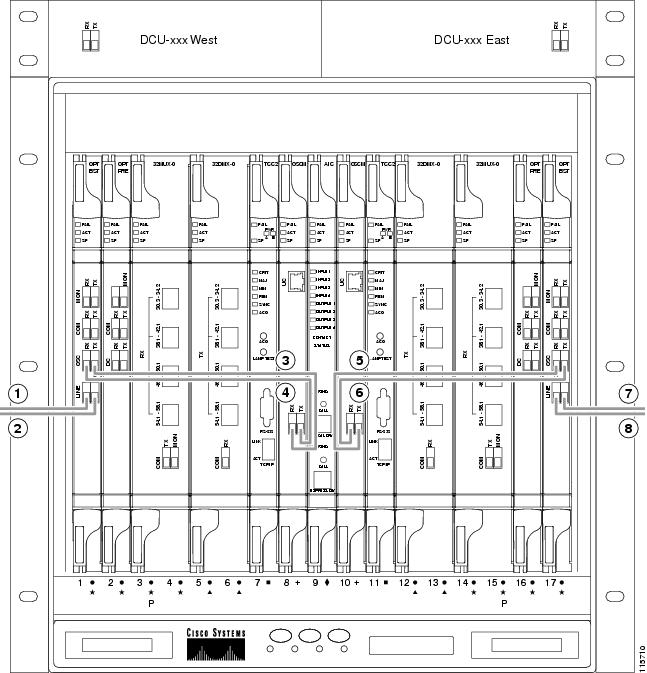
ステップ 2![]() ファイバの一端をウェスト OPT-BST または OSC-CSM LINE TX コネクタに接続し、他端を隣接ノードのイースト OPT-BST または OSC-CSM LINE RX コネクタに接続します。逆方向の接続(イーストからウェスト、TX から RX)についても同じ作業を繰り返します。ウェスト回線ポートを隣接ノードのイースト回線ポートに常に接続します。
ファイバの一端をウェスト OPT-BST または OSC-CSM LINE TX コネクタに接続し、他端を隣接ノードのイースト OPT-BST または OSC-CSM LINE RX コネクタに接続します。逆方向の接続(イーストからウェスト、TX から RX)についても同じ作業を繰り返します。ウェスト回線ポートを隣接ノードのイースト回線ポートに常に接続します。
(注) OSC 終端の作成後(G38 OSC 終端のプロビジョニング を参照)、送信ファイバと受信ファイバが正しく接続されていない場合、カードに SF LED が表示されます。たとえば、RX ポートが別の RX ポートに接続されている、または TX ポートが別の TX ポートに接続されているような場合です。
ステップ 3![]() OSCM カードが取り付けられていない場合は、ステップ 4 に進みます。OSCM カードが取り付けられている場合は、次の作業を行います。
OSCM カードが取り付けられていない場合は、ステップ 4 に進みます。OSCM カードが取り付けられている場合は、次の作業を行います。
a.![]() ファイバの一端をウェスト OPT-BST OSC RX コネクタに接続し、他端をウェスト OSCM OSC TX コネクタに接続します。
ファイバの一端をウェスト OPT-BST OSC RX コネクタに接続し、他端をウェスト OSCM OSC TX コネクタに接続します。
b.![]() 別のファイバの一端をウェスト OSCM OSC RX コネクタに接続し、他端をウェスト OPT-BST OSC TX コネクタに接続します。
別のファイバの一端をウェスト OSCM OSC RX コネクタに接続し、他端をウェスト OPT-BST OSC TX コネクタに接続します。
c.![]() ファイバの一端をイースト OPT-BST OSC RX コネクタに接続し、他端をイースト OSCM TX コネクタに接続します。
ファイバの一端をイースト OPT-BST OSC RX コネクタに接続し、他端をイースト OSCM TX コネクタに接続します。
d.![]() 別のファイバの一端をイースト OSCM OSC RX コネクタに接続し、他端をイースト OPT-BST OSC TX コネクタに接続します。
別のファイバの一端をイースト OSCM OSC RX コネクタに接続し、他端をイースト OPT-BST OSC TX コネクタに接続します。
ステップ 4![]() ネットワーク内の各ノードで、ステップ 2 とステップ
ネットワーク内の各ノードで、ステップ 2 とステップ ![]() 3 を繰り返します。
3 を繰り返します。
DLP-G66 ハブ ノードに対する光ファイバ ケーブルの取り付け
ステップ 1![]() 接続を行う際には、Cisco MetroPlanner の内部接続テーブルを参照してください。ハブ ノードの接続を開始する前に次の規則を確認します。
接続を行う際には、Cisco MetroPlanner の内部接続テーブルを参照してください。ハブ ノードの接続を開始する前に次の規則を確認します。
•![]() ウェスト OPT-BST または OSC-CSM カードの共通(COM)TX ポートは、ウェスト OPT-PRE COM RX ポートまたはウェスト 32DMX-O COM RX ポートに接続されます。
ウェスト OPT-BST または OSC-CSM カードの共通(COM)TX ポートは、ウェスト OPT-PRE COM RX ポートまたはウェスト 32DMX-O COM RX ポートに接続されます。
•![]() ウェスト OPT-PRE COM TX ポートは、ウェスト 32DMX-O COM RX ポートに接続されます。
ウェスト OPT-PRE COM TX ポートは、ウェスト 32DMX-O COM RX ポートに接続されます。
•![]() ウェスト 32MUX-O COM TX ポートは、ウェスト OPT-BST またはウェスト OSC-CSM COM RX ポートに接続されます。
ウェスト 32MUX-O COM TX ポートは、ウェスト OPT-BST またはウェスト OSC-CSM COM RX ポートに接続されます。
•![]() イースト 32MUX-O COM TX ポートは、イースト OPT-BST または OSC-CSM COM RX ポートに接続されます。
イースト 32MUX-O COM TX ポートは、イースト OPT-BST または OSC-CSM COM RX ポートに接続されます。
•![]() イースト OPT-BST またはイースト OSC-CSM COM TX ポートは、イースト OPT-PRE COM RX ポートまたはイースト 32DMX-O COM RX ポートに接続されます。
イースト OPT-BST またはイースト OSC-CSM COM TX ポートは、イースト OPT-PRE COM RX ポートまたはイースト 32DMX-O COM RX ポートに接続されます。
•![]() イースト OPT-PRE COM TX ポートは、イースト 32DMX-O RX ポートに接続されます。
イースト OPT-PRE COM TX ポートは、イースト 32DMX-O RX ポートに接続されます。
図3-12 に、ハブ ノードとそのケーブル接続の例を示します。この例では、OSCM カードが取り付けられています。OSC-CSM の場合、通常スロット 1 と 17 に取り付けられます。
(注) Cisco MetroPlanner の内部接続テーブルを基にして、光ファイバケーブルを取り付けてください。
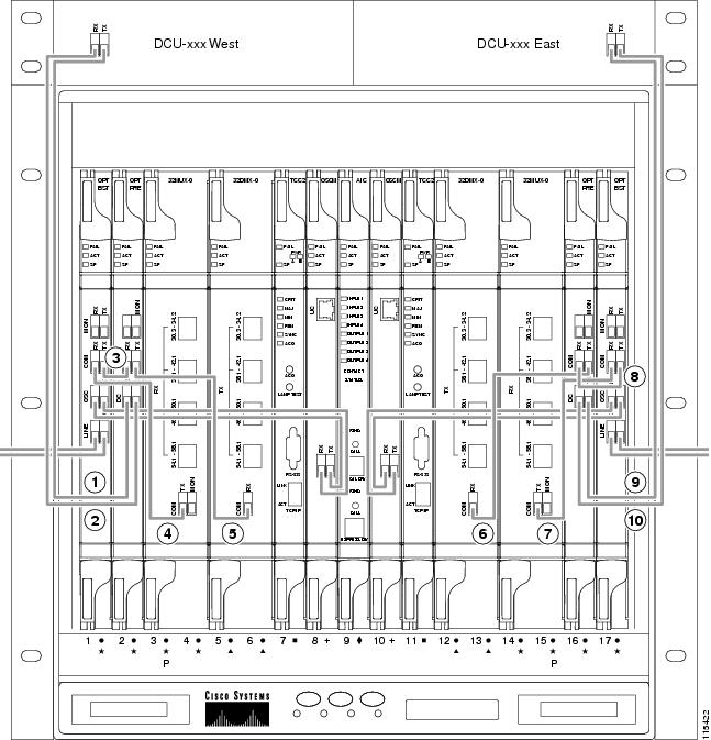
|
|
ウェスト DCU TX をウェスト OPT-PRE DC RX に接続1 |
|
|
|
|
|
||
|
|
|
||
|
|
|
||
|
|
|
| 1.DCU が取り付けられていない場合、5 dB の減衰ループを OPT-PRE DC ポートの間に取り付ける必要があります。 |
ステップ 2![]() 光ファイバ ケーブルの一端を所定の RX ポートに、他端を所定の TX ポートに接続します。
光ファイバ ケーブルの一端を所定の RX ポートに、他端を所定の TX ポートに接続します。
(注) OSC 終端の作成後(G38 OSC 終端のプロビジョニング を参照)、送信ファイバと受信ファイバが正しく接続されていない場合、カードに SF LED が表示されます。たとえば、RX ポートが別の RX ポートに接続されている、または TX ポートが別の TX ポートに接続されているような場合です。
ステップ 3![]() サイト計画に従って、ノードの接続が完了するまで、ステップ 2 を繰り返します。
サイト計画に従って、ノードの接続が完了するまで、ステップ 2 を繰り返します。
DLP-G67 終端ノードに対する光ファイバ ケーブルの取り付け
ステップ 1![]() 接続を行う際には、Cisco MetroPlanner の内部接続テーブルを参照してください。終端ノードの接続を開始する前に次の規則を確認します。
接続を行う際には、Cisco MetroPlanner の内部接続テーブルを参照してください。終端ノードの接続を開始する前に次の規則を確認します。
•![]() ターミナル サイトには、片側しかありません(これに対し、ハブ ノードには両側があります)。終端側にはイーストとウェストがあります。
ターミナル サイトには、片側しかありません(これに対し、ハブ ノードには両側があります)。終端側にはイーストとウェストがあります。
•![]() 終端側 OPT-BST または OSC-CSM カードの共通(COM)TX ポートは、終端側 OPT-PRE COM RX ポートまたは 32DMX-O COM RX ポートに接続されます。
終端側 OPT-BST または OSC-CSM カードの共通(COM)TX ポートは、終端側 OPT-PRE COM RX ポートまたは 32DMX-O COM RX ポートに接続されます。
•![]() 終端側 OPT-PRE COM TX ポートは、終端側 32DMX-O COM RX ポートに接続されます。
終端側 OPT-PRE COM TX ポートは、終端側 32DMX-O COM RX ポートに接続されます。
•![]() 終端側 32MUX-O COM TX ポートは、終端側 OPT-BST または OSC-CSM COM RX ポートに接続されます。
終端側 32MUX-O COM TX ポートは、終端側 OPT-BST または OSC-CSM COM RX ポートに接続されます。
ステップ 2![]() 光ファイバ ケーブルの一端を所定の RX ポートに、他端を所定の TX ポートに接続します。
光ファイバ ケーブルの一端を所定の RX ポートに、他端を所定の TX ポートに接続します。
(注) OSC 終端の作成後(G38 OSC 終端のプロビジョニング を参照)、送信ファイバと受信ファイバが正しく接続されていない場合、カードに SF LED が表示されます。たとえば、RX ポートが別の RX ポートに接続されている、または TX ポートが別の TX ポートに接続されているような場合です。
ステップ 3![]() サイト計画に従って、ノードの接続が完了するまで、ステップ 2 を繰り返します。
サイト計画に従って、ノードの接続が完了するまで、ステップ 2 を繰り返します。
DLP-G68 光回線増幅ノードでの光ファイバ ケーブルの取り付け
ステップ 1![]() 接続を行う際には、Cisco MetroPlanner の内部接続テーブルを参照してください。光回線増幅ノードの接続を開始する前に次の規則を確認します。
接続を行う際には、Cisco MetroPlanner の内部接続テーブルを参照してください。光回線増幅ノードの接続を開始する前に次の規則を確認します。
•![]() 光回線増幅ノードのレイアウトでは、OPT-PRE と OPT-BST のあらゆる組み合わせが可能で、ウェストからイースト方向、およびイーストからウェスト方向の構成で非対称のカード選定を使用できます。指定された回線方向に対して、次の 4 つの構成が考えられます。
光回線増幅ノードのレイアウトでは、OPT-PRE と OPT-BST のあらゆる組み合わせが可能で、ウェストからイースト方向、およびイーストからウェスト方向の構成で非対称のカード選定を使用できます。指定された回線方向に対して、次の 4 つの構成が考えられます。
–![]() 前置増幅とブースタ増幅の両方(ただし、光回線増幅ノードには少なくとも 1 方向での増幅があります)
前置増幅とブースタ増幅の両方(ただし、光回線増幅ノードには少なくとも 1 方向での増幅があります)
•![]() ウェスト OPT-PRE カードが取り付けられている場合:
ウェスト OPT-PRE カードが取り付けられている場合:
–![]() ウェスト OSC-CSM または OPT-BST COM TX ポートは、ウェスト OPT-PRE COM RX ポートに接続されます。
ウェスト OSC-CSM または OPT-BST COM TX ポートは、ウェスト OPT-PRE COM RX ポートに接続されます。
–![]() ウェスト OPT-PRE COM TX ポートは、イースト OSC-CSM または OPT-BST COM RX ポートに接続されます。
ウェスト OPT-PRE COM TX ポートは、イースト OSC-CSM または OPT-BST COM RX ポートに接続されます。
•![]() ウェスト OPT-PRE カードが取り付けられていない場合、ウェスト OSC-CSM または OPT-BST COM TX ポートは、イースト OSC-CSM または OPT-BST COM RX ポートに接続されます。
ウェスト OPT-PRE カードが取り付けられていない場合、ウェスト OSC-CSM または OPT-BST COM TX ポートは、イースト OSC-CSM または OPT-BST COM RX ポートに接続されます。
•![]() イースト OPT-PRE カードが取り付けられている場合:
イースト OPT-PRE カードが取り付けられている場合:
–![]() イースト OSC-CSM または OPT-BST COM TX ポートは、イースト OPT-PRE COM RX ポートに接続されます。
イースト OSC-CSM または OPT-BST COM TX ポートは、イースト OPT-PRE COM RX ポートに接続されます。
–![]() イースト OPT-PRE COM TX ポートは、ウェスト OSC-CSM または OPT-BST COM RX ポートに接続されます。
イースト OPT-PRE COM TX ポートは、ウェスト OSC-CSM または OPT-BST COM RX ポートに接続されます。
•![]() イースト OPT-PRE カードが取り付けられていない場合、イースト OSC-CSM または OPT-BST COM TX ポートは、ウェスト OSC-CSM または OPT-BST COM RX ポートに接続されます。
イースト OPT-PRE カードが取り付けられていない場合、イースト OSC-CSM または OPT-BST COM TX ポートは、ウェスト OSC-CSM または OPT-BST COM RX ポートに接続されます。
図3-13 に、回線増幅器ノードとそのケーブル接続の例を示します。
(注) Cisco MetroPlanner の内部接続テーブルを基にして、光ファイバケーブルを取り付けてください。
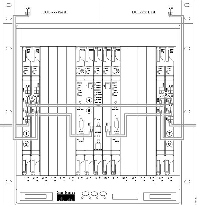
|
|
ウェスト DCU TX をウェスト OPT-PRE DC RX に接続2 |
|
|
|
|
|
||
|
|
|
||
|
|
|
| 2.DCU が取り付けられていない場合、5 dB の減衰ループを OPT-PRE DC ポートの間に取り付ける必要があります。 |
ステップ 2![]() 光ファイバ ケーブルの一端を所定の RX ポートに、他端を所定の TX ポートに接続します。
光ファイバ ケーブルの一端を所定の RX ポートに、他端を所定の TX ポートに接続します。
(注) OSC 終端の作成後(G38 OSC 終端のプロビジョニング を参照)、送信ファイバと受信ファイバが正しく接続されていない場合、カードに SF LED が表示されます。たとえば、RX ポートが別の RX ポートに接続されている、または TX ポートが別の TX ポートに接続されているような場合です。
ステップ 3![]() サイト計画に従って、ノードの接続が完了するまで、ステップ 2 を繰り返します。
サイト計画に従って、ノードの接続が完了するまで、ステップ 2 を繰り返します。
DLP-G69 OSC 再生ノードに対する光ファイバ ケーブルの取り付け
ステップ 1![]() 接続を行う際には、Cisco MetroPlanner の内部接続テーブルを参照してください。OSC 再生ノードの接続を開始する前に次の規則を確認します。
接続を行う際には、Cisco MetroPlanner の内部接続テーブルを参照してください。OSC 再生ノードの接続を開始する前に次の規則を確認します。
•![]() ウェスト OSC-CSM COM TX ポートは、イースト OSC-CSM COM RX ポートに接続されます。
ウェスト OSC-CSM COM TX ポートは、イースト OSC-CSM COM RX ポートに接続されます。
•![]() ウェスト OSC-CSM COM RX ポートは、イースト OSC-CSM COM TX ポートに接続されます。
ウェスト OSC-CSM COM RX ポートは、イースト OSC-CSM COM TX ポートに接続されます。
•![]() スロット 2~5 および 12~16 は、TXP/MXP カード用です。
スロット 2~5 および 12~16 は、TXP/MXP カード用です。
図3-14 に、OSC 再生ノードとそのケーブル接続の例を示します。
(注) Cisco MetroPlanner の内部接続テーブルを基にして、光ファイバケーブルを取り付けてください。
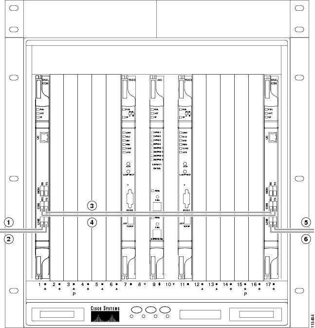
ステップ 2![]() 光ファイバ ケーブルの一端を所定の RX ポートに、他端を所定の TX ポートに接続します。
光ファイバ ケーブルの一端を所定の RX ポートに、他端を所定の TX ポートに接続します。
(注) OSC 終端の作成後(G38 OSC 終端のプロビジョニング を参照)、送信ファイバと受信ファイバが正しく接続されていない場合、カードに SF LED が表示されます。たとえば、RX ポートが別の RX ポートに接続されている、または TX ポートが別の TX ポートに接続されているような場合です。
ステップ 3![]() サイト計画に従って、ノードの接続が完了するまで、ステップ 2 を繰り返します。
サイト計画に従って、ノードの接続が完了するまで、ステップ 2 を繰り返します。
DLP-G70 増幅またはパッシブ OADM ノードでの光ファイバ ケーブルの取り付け
この作業では、DWDM シェルフ内の増幅またはパッシブ Optical Add/Drop Multiplexing(OADM; 光アド/ドロップ多重化)ノードへ光ファイバ ケーブルを取り付けるための手順、ルール、および例について説明します。 |
|
(注) 増幅 OADM ノードには、OPT-PRE カードまたは OPT-BST カード、またはその両方が含まれます。パッシブ OADM ノードにはどちらも含まれません。両ノードには、アド/ドロップ チャネルまたはバンド カードが含まれます。
ステップ 1![]() 接続を行う際には、Cisco MetroPlanner の内部接続テーブルを参照してください。増幅またはパッシブ OADM ノードで光ファイバ接続を開始する前に、すべての OADM 接続に対して次の規則を確認します。
接続を行う際には、Cisco MetroPlanner の内部接続テーブルを参照してください。増幅またはパッシブ OADM ノードで光ファイバ接続を開始する前に、すべての OADM 接続に対して次の規則を確認します。
•![]() OADM ノードの両側が対称である必要はありません。Cisco MetroPlanner では、それぞれの側で、次の 4 つの構成のうちの 1 つを作成できます。
OADM ノードの両側が対称である必要はありません。Cisco MetroPlanner では、それぞれの側で、次の 4 つの構成のうちの 1 つを作成できます。
ステップ 2![]() OADM ノードのエクスプレス パス ケーブル接続に関する次のルールを参考にしてください。
OADM ノードのエクスプレス パス ケーブル接続に関する次のルールを参考にしてください。
•![]() TX ポートは RX ポートのみに接続されなければなりません。
TX ポートは RX ポートのみに接続されなければなりません。
•![]() EXP ポートは、すべてイースト側に属する AD-xC または AD-xB カード間の COM ポートのみに接続されます(つまり、これらのポートはデイジーチェーンになっています)。
EXP ポートは、すべてイースト側に属する AD-xC または AD-xB カード間の COM ポートのみに接続されます(つまり、これらのポートはデイジーチェーンになっています)。
•![]() EXP ポートは、すべてウェスト側に属する AD-xC または AD-xB カード間の COM ポートのみに接続されます(つまり、これらのポートはデイジーチェーンになっています)。
EXP ポートは、すべてウェスト側に属する AD-xC または AD-xB カード間の COM ポートのみに接続されます(つまり、これらのポートはデイジーチェーンになっています)。
•![]() ウェスト側の最後の AD-xC または AD-xB カードの EXP ポートは、イースト側の最初の AD-xC または AD-xB カードの EXP ポートに接続されます。
ウェスト側の最後の AD-xC または AD-xB カードの EXP ポートは、イースト側の最初の AD-xC または AD-xB カードの EXP ポートに接続されます。
•![]() OPT-BST COM RX ポートは、スロット位置が最も近い AD-xC または AD-xB COM TX ポートに接続されます。
OPT-BST COM RX ポートは、スロット位置が最も近い AD-xC または AD-xB COM TX ポートに接続されます。
•![]() OPT-PRE COM TX ポートは、スロット位置が最も近い AD-xC または AD-xB COM RX ポートに接続されます。
OPT-PRE COM TX ポートは、スロット位置が最も近い AD-xC または AD-xB COM RX ポートに接続されます。
•![]() OADM カードが隣接スロットに位置している場合、TCC2/TCC2P カードでは、EXP ポートおよび COM ポートの間がデイジーチェーンで接続されているとみなします。
OADM カードが隣接スロットに位置している場合、TCC2/TCC2P カードでは、EXP ポートおよび COM ポートの間がデイジーチェーンで接続されているとみなします。
•![]() 最初のウェスト AD-xC または AD-xB カードの COM RX ポートは、ウェスト OPT-PRE または OSC-CSM COM TX ポートに接続されます。
最初のウェスト AD-xC または AD-xB カードの COM RX ポートは、ウェスト OPT-PRE または OSC-CSM COM TX ポートに接続されます。
•![]() 最初のウェスト AD-xC または AD-xB カードの COM TX ポートは、ウェスト OPT-BST または OSC-CSM COM RX ポートに接続されます。
最初のウェスト AD-xC または AD-xB カードの COM TX ポートは、ウェスト OPT-BST または OSC-CSM COM RX ポートに接続されます。
•![]() 最初のイースト AD-xC または AD-xB カードの COM RX ポートは、イースト OPT-PRE または OSC-CSM COM TX ポートに接続されます。
最初のイースト AD-xC または AD-xB カードの COM RX ポートは、イースト OPT-PRE または OSC-CSM COM TX ポートに接続されます。
•![]() 最初のイースト AD-xC または AD-xB カードの COM TX ポートは、イースト OPT-BST または OSC-CSM RX ポートに接続されます。
最初のイースト AD-xC または AD-xB カードの COM TX ポートは、イースト OPT-BST または OSC-CSM RX ポートに接続されます。
•![]() ウェスト OPT-PRE がある場合、ウェスト OPT-BST または OSC-CSM COM TX ポートは、ウェスト OPT-PRE COM RX ポートに接続されます。
ウェスト OPT-PRE がある場合、ウェスト OPT-BST または OSC-CSM COM TX ポートは、ウェスト OPT-PRE COM RX ポートに接続されます。
•![]() イースト OPT-PRE がある場合、イースト OPT-BST または OSC-CSM COM TX ポートは、イースト OPT-PRE COM RX ポートに接続されます。
イースト OPT-PRE がある場合、イースト OPT-BST または OSC-CSM COM TX ポートは、イースト OPT-PRE COM RX ポートに接続されます。
ステップ 3![]() OADM ノードのアド/ドロップ パス ケーブル接続に関する次のルールを参考にしてください。
OADM ノードのアド/ドロップ パス ケーブル接続に関する次のルールを参考にしてください。
•![]() AD-xB アド/ドロップ(RX または TX)ポートは、次のポートのみに接続されます。
AD-xB アド/ドロップ(RX または TX)ポートは、次のポートのみに接続されます。
–![]() 4MD COM TX または 4MD COM RX ポート
4MD COM TX または 4MD COM RX ポート
–![]() もう 1 つの AD-xB アド/ドロップ ポート(パススルー構成)
もう 1 つの AD-xB アド/ドロップ ポート(パススルー構成)
•![]() AD-xB アド/ドロップ バンド ポートは、同じバンドに属している 4MD カードのみに接続されます。
AD-xB アド/ドロップ バンド ポートは、同じバンドに属している 4MD カードのみに接続されます。
•![]() それぞれの特定の AD-xB に対して、そのバンド カードのアド ポートとドロップ ポートは、同じ 4MD カードの COM TX ポートおよび COM RX ポートに接続されます。
それぞれの特定の AD-xB に対して、そのバンド カードのアド ポートとドロップ ポートは、同じ 4MD カードの COM TX ポートおよび COM RX ポートに接続されます。
•![]() AD-xB および 4MD カードは、同じ側にあります(接続されたポートは、すべて同じ回線方向です)。
AD-xB および 4MD カードは、同じ側にあります(接続されたポートは、すべて同じ回線方向です)。
ステップ 4![]() OADM ノードのパススルー パス ケーブル接続に関する次のルールを参考にしてください。
OADM ノードのパススルー パス ケーブル接続に関する次のルールを参考にしてください。
•![]() パススルー接続は、同じバンドまたはチャネルおよび同じ回線方向のアド ポートとドロップ ポート間でのみ確立されます。
パススルー接続は、同じバンドまたはチャネルおよび同じ回線方向のアド ポートとドロップ ポート間でのみ確立されます。
•![]() AD-xC または AD-xB チャネル アド/ドロップ ポートを、他の AD-xC または AD-xB アド/ドロップ ポートのみに接続します(パススルー構成として)。
AD-xC または AD-xB チャネル アド/ドロップ ポートを、他の AD-xC または AD-xB アド/ドロップ ポートのみに接続します(パススルー構成として)。
•![]() アド(RX)ポートは、ドロップ(TX)ポートのみに接続されます。
アド(RX)ポートは、ドロップ(TX)ポートのみに接続されます。
•![]() 4MD クライアント入出力ポートを他の 4MD クライアント入出力ポートのみに接続します。
4MD クライアント入出力ポートを他の 4MD クライアント入出力ポートのみに接続します。
•![]() ウェスト AD-xB ドロップ(TX)ポートは、対応するウェスト 4MD COM RX ポートに接続されます。
ウェスト AD-xB ドロップ(TX)ポートは、対応するウェスト 4MD COM RX ポートに接続されます。
•![]() ウェスト AD-xB アド(RX)ポートは、対応するウェスト 4MD COM TX ポートに接続されます。
ウェスト AD-xB アド(RX)ポートは、対応するウェスト 4MD COM TX ポートに接続されます。
•![]() イースト AD-xB ドロップ(TX)ポートは、対応するイースト 4MD COM RX ポートに接続されます。
イースト AD-xB ドロップ(TX)ポートは、対応するイースト 4MD COM RX ポートに接続されます。
•![]() イースト AD-xB アド(RX)ポートは、対応するイースト 4MD COM TX ポートに接続されます。
イースト AD-xB アド(RX)ポートは、対応するイースト 4MD COM TX ポートに接続されます。
図3-15 に、AD-1C-xx.x カードが取り付けられた増幅 OADM ノードの例を示します。
(注) 常に Cisco MetroPlanner の内部接続テーブルを基にして、光ファイバケーブルを取り付けてください。
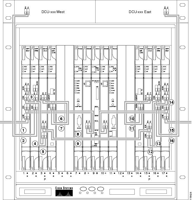
|
|
ウェスト DCU TX をウェスト OPT-PRE DC RX に接続3 |
|
|
|
|
|
||
|
|
|
||
|
|
|
||
|
|
|
||
|
|
|
||
|
|
|
||
|
|
|
| 3.DCU が取り付けられていない場合、5 dB の減衰ループを OPT-PRE DC ポートの間に取り付ける必要があります。 |
図3-16 に、2 枚の AD-1C-xx.x カードが取り付けられたパッシブ OADM ノードの例を示します。
(注) 常に Cisco MetroPlanner の内部接続テーブルを基にして、光ファイバケーブルを取り付けてください。
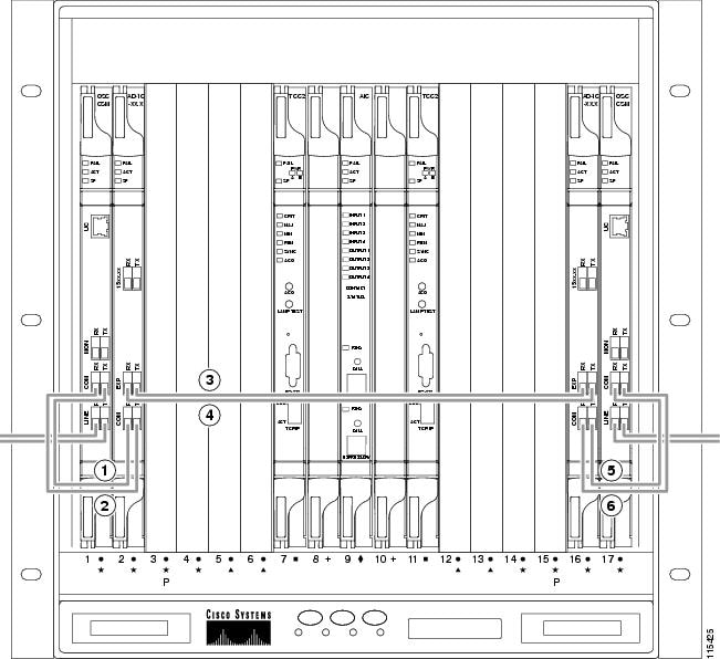
|
|
|
||
|
|
|
||
|
|
|
ステップ 5![]() 光ファイバ ケーブルの一端を RX ポートに、他端を TX ポートに接続します。
光ファイバ ケーブルの一端を RX ポートに、他端を TX ポートに接続します。
(注) OSC 終端の作成後(G38 OSC 終端のプロビジョニング を参照)、送信ファイバと受信ファイバが正しく接続されていない場合、カードに SF LED が表示されます。たとえば、RX ポートが別の RX ポートに接続されている、または TX ポートが別の TX ポートに接続されているような場合です。
ステップ 6![]() サイト計画に従って、ノードの接続が完了するまで、ステップ 5 を繰り返します。
サイト計画に従って、ノードの接続が完了するまで、ステップ 5 を繰り返します。
DLP-G71 ROADM ノードに対する光ファイバ ケーブルの取り付け
この作業では、DWDM シェルフ内の Reconfigurable Optical Add/Drop Multiplexing(ROADM; 再設定可能光アド/ドロップ多重化装置)ノードへ光ファイバ ケーブルを取り付けるための手順、ルール、および例について説明します。 |
|
(注) 間違いを防止すために、右端のスロットをイースト ポートとし、左端のスロットをウェスト ポートとして、光ファイバ ケーブルを接続します。あるノードのイースト ポートに接続されたファイバを、隣接ノードのウェスト ポートに接続する必要があります。
ステップ 1![]() 接続を行う際には、Cisco MetroPlanner の内部接続テーブルを参照してください。ROADM ノードに対する光ファイバ ケーブルの接続を開始する前に、次の規則を確認します。
接続を行う際には、Cisco MetroPlanner の内部接続テーブルを参照してください。ROADM ノードに対する光ファイバ ケーブルの接続を開始する前に、次の規則を確認します。
•![]() ウェスト OPT-BST または OSC-CSM COM TX ポートは、ウェスト OPT-PRE COM RX ポートに接続されます。
ウェスト OPT-BST または OSC-CSM COM TX ポートは、ウェスト OPT-PRE COM RX ポートに接続されます。
•![]() ウェスト OPT-BST または OSC-CSM COM RX ポートは、ウェスト 32WSS COM TX ポートに接続されます。
ウェスト OPT-BST または OSC-CSM COM RX ポートは、ウェスト 32WSS COM TX ポートに接続されます。
•![]() ウェスト OPT-BST(取り付け済みの場合)OSC TX ポートは、ウェスト OSCM RX ポートに接続されます。
ウェスト OPT-BST(取り付け済みの場合)OSC TX ポートは、ウェスト OSCM RX ポートに接続されます。
•![]() ウェスト OPT-BST(取り付け済みの場合)OSC RX ポートは、ウェスト OSCM TX ポートに接続されます。
ウェスト OPT-BST(取り付け済みの場合)OSC RX ポートは、ウェスト OSCM TX ポートに接続されます。
•![]() ウェスト 32WSS EXP TX ポートは、イースト 32WSS EXP RX ポートに接続されます。
ウェスト 32WSS EXP TX ポートは、イースト 32WSS EXP RX ポートに接続されます。
•![]() ウェスト 32WSS EXP RX ポートは、イースト 32WSS EXP TX ポートに接続されます。
ウェスト 32WSS EXP RX ポートは、イースト 32WSS EXP TX ポートに接続されます。
•![]() ウェスト 32WSS DROP TX ポートは、ウェスト 32DMX COM RX ポートに接続されます。
ウェスト 32WSS DROP TX ポートは、ウェスト 32DMX COM RX ポートに接続されます。
•![]() イースト OPT-BST または OSC-CSM COM TX ポートは、イースト OPT-PRE COM RX ポートに接続されます。
イースト OPT-BST または OSC-CSM COM TX ポートは、イースト OPT-PRE COM RX ポートに接続されます。
•![]() イースト OPT-BST または OSC-CSM COM RX ポートは、イースト 32WSS COM TX ポートに接続されます。
イースト OPT-BST または OSC-CSM COM RX ポートは、イースト 32WSS COM TX ポートに接続されます。
•![]() イースト OPT-BST(取り付け済みの場合)OSC TX ポートは、イースト OSCM RX ポートに接続されます。
イースト OPT-BST(取り付け済みの場合)OSC TX ポートは、イースト OSCM RX ポートに接続されます。
•![]() イースト OPT-BST(取り付け済みの場合)OSC RX ポートは、イースト OSCM TX ポートに接続されます。
イースト OPT-BST(取り付け済みの場合)OSC RX ポートは、イースト OSCM TX ポートに接続されます。
•![]() イースト 32WSS DROP TX ポートは、イースト 32DMX COM RX ポートに接続されます。
イースト 32WSS DROP TX ポートは、イースト 32DMX COM RX ポートに接続されます。
図3-17 に、増幅 ROADM ノードとそのケーブル接続の例を示します。
(注) 常に Cisco MetroPlanner の内部接続テーブルを基にして、光ファイバケーブルを取り付けてください。
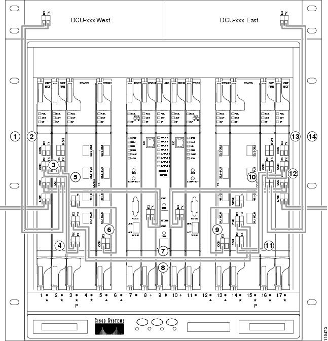
|
|
ウェスト DCU TX をウェスト OPT-PRE DC RX に接続4 |
|
|
|
|
|
||
|
|
|
||
|
|
|
||
|
|
|
||
|
|
|
||
|
|
|
| 4.DCU が取り付けられていない場合、5dB の減衰ループを OPT-PRE DC ポートの間に取り付ける必要があります。 |
(注) OSC 終端の作成後(G38 OSC 終端のプロビジョニング を参照)、送信ファイバと受信ファイバが正しく接続されていない場合、カードに SF LED が表示されます。たとえば、RX ポートが別の RX ポートに接続されている、または TX ポートが別の TX ポートに接続されているような場合です。
ステップ 2![]() 光ファイバ ケーブルの一端を所定の RX ポートに、他端を所定の TX ポートに接続します。
光ファイバ ケーブルの一端を所定の RX ポートに、他端を所定の TX ポートに接続します。
ステップ 3![]() サイト計画に従って、ノードの接続が完了するまで、ステップ 2 を繰り返します。
サイト計画に従って、ノードの接続が完了するまで、ステップ 2 を繰り返します。
ステップ 1![]() ケーブル管理トレイの折畳式の前面扉を開きます。
ケーブル管理トレイの折畳式の前面扉を開きます。
ステップ 2![]() カードの前面プレート上の光ファイバ ケーブルを、前面プレート上のファイバ クリップを通して配線します。ファイバ クリップは、32MUX-O、32DMX-O、OSCM、OPT-PRE、および OPT-BST カードの前面プレートに工場で取り付けられています。
カードの前面プレート上の光ファイバ ケーブルを、前面プレート上のファイバ クリップを通して配線します。ファイバ クリップは、32MUX-O、32DMX-O、OSCM、OPT-PRE、および OPT-BST カードの前面プレートに工場で取り付けられています。
ステップ 3![]() 光ファイバ ケーブルをケーブル管理トレイに配線します。
光ファイバ ケーブルをケーブル管理トレイに配線します。
ステップ 4![]() 光ファイバ ケーブルを、シェルフ アセンブリのそれぞれの側にある切り欠き部を通して、ケーブル管理トレイのいずれかの側から外部に配線します。方向反転可能なファイバ ガイドを使用して、希望する側から外部にケーブルを配線します。
光ファイバ ケーブルを、シェルフ アセンブリのそれぞれの側にある切り欠き部を通して、ケーブル管理トレイのいずれかの側から外部に配線します。方向反転可能なファイバ ガイドを使用して、希望する側から外部にケーブルを配線します。
ステップ 5![]() 前面のコンパートメント内のすべての光ファイバ ケーブルが適切に配線されたら、折畳式の前面扉を閉めます。
前面のコンパートメント内のすべての光ファイバ ケーブルが適切に配線されたら、折畳式の前面扉を閉めます。
ステップ 1![]() DWDM ケーブル接続をプロビジョニングするノードで 「G46 CTC へのログイン」 を実行します。すでにログインしている場合は、ステップ 2 に進みます。
DWDM ケーブル接続をプロビジョニングするノードで 「G46 CTC へのログイン」 を実行します。すでにログインしている場合は、ステップ 2 に進みます。
a.![]() アラーム フィルタ機能がオフであることを確認します。必要に応じて、「G128 アラーム フィルタのディセーブル化」を参照してください。
アラーム フィルタ機能がオフであることを確認します。必要に応じて、「G128 アラーム フィルタのディセーブル化」を参照してください。
b.![]() 原因不明の機器アラームがノード上で表示されていないことを確認します。アラームが表示されている場合は、操作を続ける前にこれらのアラームをよく調査し解除してください。手順については、『 Cisco ONS 15454 Troubleshooting Guide 』または『 Cisco ONS 15454 SDH Troubleshooting Guide 』を参照してください。
原因不明の機器アラームがノード上で表示されていないことを確認します。アラームが表示されている場合は、操作を続ける前にこれらのアラームをよく調査し解除してください。手順については、『 Cisco ONS 15454 Troubleshooting Guide 』または『 Cisco ONS 15454 SDH Troubleshooting Guide 』を参照してください。
ステップ 3![]() Provisioning > WDM-ANS > Connections タブをクリックします。
Provisioning > WDM-ANS > Connections タブをクリックします。
ステップ 4![]() Calculate Connections をクリックします。
Calculate Connections をクリックします。
CTC は、ONS 15454 シェルフに取り付けられたカードに互換性があること、および DWDM ノードに必要なカードがすべて取り付けられていることを確認します。これらの点を確認すると、CTC はプロビジョニングされる接続を算出します。OPT-BST カードは取り付けられているが OSCM カードが取り付けられていないなど、カードに互換性がない、またはカードが検出されない場合、接続の算出中にエラーが発生します。
(注) 接続の算出には、Cisco MetroPlanner のサイト計画は使用されません。物理的に取り付けられたカードに基づいて算出されます。サイト計画ではハブ ノードが要求されているのにもかかわらず、OADM カードが取り付けられている場合、CTC は OADM ノード用のカードに基づいて接続を算出します。
ステップ 5![]() エラーが発生しない場合は、ステップ 6 に進みます。エラーが表示された場合は、シェルフに取り付けられたカードが、Cisco MetroPlanner によって算出されたシェルフ計画と一致していることを確認してください。カードが正しく取り付けられていない場合、またはカードが検出されない場合は、「G30 DWDM カードの取り付け」 の手順に従ってカードを正しく取り付け直してください。
エラーが発生しない場合は、ステップ 6 に進みます。エラーが表示された場合は、シェルフに取り付けられたカードが、Cisco MetroPlanner によって算出されたシェルフ計画と一致していることを確認してください。カードが正しく取り付けられていない場合、またはカードが検出されない場合は、「G30 DWDM カードの取り付け」 の手順に従ってカードを正しく取り付け直してください。
ステップ 6![]() CTC Connection タブの接続が Cisco MetroPlanner 内部接続ファイルの接続と一致しているかどうか確認します(CTC Connections タブには、OPT-PRE 分散接続、スパン接続、TXP/MXP カードと DWDM カード間の接続は表示されません)。
CTC Connection タブの接続が Cisco MetroPlanner 内部接続ファイルの接続と一致しているかどうか確認します(CTC Connections タブには、OPT-PRE 分散接続、スパン接続、TXP/MXP カードと DWDM カード間の接続は表示されません)。
ステップ 7![]() 手動でプロビジョニングする必要がある接続に関しては、「G72 DWDM 接続の作成」を実行してください(手動で作成する必要がある接続は、Cisco MetroPlanner 接続ファイルの Manually Set カラムに「Yes」と表示されます)。接続を削除する必要がある場合は、「G73 DWDM 接続の削除」 の作業を行います。
手動でプロビジョニングする必要がある接続に関しては、「G72 DWDM 接続の作成」を実行してください(手動で作成する必要がある接続は、Cisco MetroPlanner 接続ファイルの Manually Set カラムに「Yes」と表示されます)。接続を削除する必要がある場合は、「G73 DWDM 接続の削除」 の作業を行います。
(注) CTC では、DWDM 接続の大部分が自動的に算出されますが、DWDM カードのタイプと位置が原因で、自動的に算出されない接続もあります。これらの接続については、手作業で作成する必要があります。たとえば、光バイパス回線に関連した接続では、手作業でプロビジョニングする必要があります。異なる種類の光ファイバ ケーブルを必要とする接続もあります。そのため、手作業でのプロビジョニングでは、さまざまなケーブル接続の必要性が強調されます。これらすべての接続について、手作業でプロビジョニングする必要があります。
ステップ 8![]() 「G37 自動ノード設定の実行」に進みます。
「G37 自動ノード設定の実行」に進みます。
ステップ 1![]() ノード ビューで、 Provisioning > WDM-ANS > Connections タブをクリックします。
ノード ビューで、 Provisioning > WDM-ANS > Connections タブをクリックします。
ステップ 3![]() Create Optical Link ダイアログボックスにあるドロップダウン リストから、From(起点)と To(終点)のスロットおよびポートを選択します。
Create Optical Link ダイアログボックスにあるドロップダウン リストから、From(起点)と To(終点)のスロットおよびポートを選択します。
ステップ 4![]() 接続が単方向の場合は、 bidirectional チェックボックスをオフにします。
接続が単方向の場合は、 bidirectional チェックボックスをオフにします。
ステップ 5![]() OK をクリックします。Connections テーブルに新規接続が表示されますが、その状態は「Uncommitted」になります。
OK をクリックします。Connections テーブルに新規接続が表示されますが、その状態は「Uncommitted」になります。
ステップ 6![]() テーブル内の新しい接続をクリックします。 Commit をクリックします。接続状態が「Connected」に変わります。
テーブル内の新しい接続をクリックします。 Commit をクリックします。接続状態が「Connected」に変わります。
ステップ 7![]() 接続を追加する必要がある場合は、追加するそれぞれの接続に対して 2 ~ 6 のステップを
接続を追加する必要がある場合は、追加するそれぞれの接続に対して 2 ~ 6 のステップを![]() 繰り返します。
繰り返します。
ステップ 1![]() ノード ビューで、 Provisioning > WDM-ANS > Connection タブをクリックします。
ノード ビューで、 Provisioning > WDM-ANS > Connection タブをクリックします。
この手順では、CTC の DWDM Automatic Node Setup(ANS; 自動ノード設定)機能を実行します。ANS は、Variable Optical Attenuator(VOA; 可変光減衰器)の値を更新して、チャネルあたりの電力が増幅器レベルで等しくなるようにします。 |
|
ステップ 1![]() 自動ノード設定を実行するノードで、「G46 CTC へのログイン」の作業を行います。すでにログインしている場合は、ステップ 2 に進みます。
自動ノード設定を実行するノードで、「G46 CTC へのログイン」の作業を行います。すでにログインしている場合は、ステップ 2 に進みます。
a.![]() アラーム フィルタ機能がオフであることを確認します。必要に応じて、「G128 アラーム フィルタのディセーブル化」を参照してください。
アラーム フィルタ機能がオフであることを確認します。必要に応じて、「G128 アラーム フィルタのディセーブル化」を参照してください。
b.![]() 説明のつかないアラームがネットワーク上に表示されていないことを確認します。アラームが表示されている場合は、操作を続ける前にこれらのアラームをよく調査し解除してください。手順については、『 Cisco ONS 15454 Troubleshooting Guide 』または『 Cisco ONS 15454 SDH Troubleshooting Guide 』を参照してください。
説明のつかないアラームがネットワーク上に表示されていないことを確認します。アラームが表示されている場合は、操作を続ける前にこれらのアラームをよく調査し解除してください。手順については、『 Cisco ONS 15454 Troubleshooting Guide 』または『 Cisco ONS 15454 SDH Troubleshooting Guide 』を参照してください。
ステップ 3![]() 「G74 Cisco MetroPlanner 設定ファイルのインポート」の作業を行います。
「G74 Cisco MetroPlanner 設定ファイルのインポート」の作業を行います。
ステップ 4![]() Cisco MetroPlanner でサイト計画を表示するか、または MetroPlanner のインストール パラメータ テーブルの印刷コピーを参照します。
Cisco MetroPlanner でサイト計画を表示するか、または MetroPlanner のインストール パラメータ テーブルの印刷コピーを参照します。
ステップ 5![]() Cisco MetroPlanner で、インストール パラメータ テーブルに移動します。 Manually Set カラムに Yes と表示されているパラメータを確認します。
Cisco MetroPlanner で、インストール パラメータ テーブルに移動します。 Manually Set カラムに Yes と表示されているパラメータを確認します。
ステップ 6![]() パラメータがプロビジョニングされるカードを CTC のカードビューに表示します。
パラメータがプロビジョニングされるカードを CTC のカードビューに表示します。
ステップ 7![]() Cisco MetroPlanner のインストール パラメータ テーブルから、指定された Calibration パラメータを入力します。 Apply をクリックします。
Cisco MetroPlanner のインストール パラメータ テーブルから、指定された Calibration パラメータを入力します。 Apply をクリックします。
ステップ 8![]() Cisco MetroPlanner のインストール パラメータ テーブルの Manually Set フィールドで、Yes と表示されているすべてのパラメータについて、ステップ 5 ~ 7 を繰り返します。
Cisco MetroPlanner のインストール パラメータ テーブルの Manually Set フィールドで、Yes と表示されているすべてのパラメータについて、ステップ 5 ~ 7 を繰り返します。
ステップ 9![]() Port Status タブをクリックします。 Launch ANS をクリックします。
Port Status タブをクリックします。 Launch ANS をクリックします。
ステップ 10![]() Apply Launch ANS ダイアログボックスで Yes をクリックします。ANS は、VOA の値を調整して、チャネルあたりの電力が増幅器レベルで等しくなるようにします。
Apply Launch ANS ダイアログボックスで Yes をクリックします。ANS は、VOA の値を調整して、チャネルあたりの電力が増幅器レベルで等しくなるようにします。
ステップ 11![]() Launch ANS 確認ダイアログボックスで OK をクリックします。
Launch ANS 確認ダイアログボックスで OK をクリックします。
ステップ 12![]() すべてのポートの Link Status カラムに、次のいずれかの状態が表示されていることを確認します。確認できた場合は、ステップ 13 に進みます。
すべてのポートの Link Status カラムに、次のいずれかの状態が表示されていることを確認します。確認できた場合は、ステップ 13 に進みます。
•![]() Success - Changed:パラメータのセットポイントが正常に再計算されました。
Success - Changed:パラメータのセットポイントが正常に再計算されました。
•![]() Success - Unchanged:パラメータのセットポイントを再計算する必要はありませんでした。
Success - Unchanged:パラメータのセットポイントを再計算する必要はありませんでした。
•![]() Not Applicable:パラメータのセットポイントはこのノード タイプには適用されません。
Not Applicable:パラメータのセットポイントはこのノード タイプには適用されません。
次のいずれかの状態が表示された場合は、記載されている指示に従ってください。
•![]() Fail - Out of Range:計算されたセットポイントが予想の範囲外にあります。「G36 ケーブル接続の算出」 を繰り返して、手動のプロビジョニングが必要な接続に注意しながら、すべての接続が正しくプロビジョニングされていることを確認します。
Fail - Out of Range:計算されたセットポイントが予想の範囲外にあります。「G36 ケーブル接続の算出」 を繰り返して、手動のプロビジョニングが必要な接続に注意しながら、すべての接続が正しくプロビジョニングされていることを確認します。
•![]() Fail - Port in IS State:ポートが使用中のため、パラメータを再計算できませんでした。ノードのターンアップの時点で、この状態が表示されることは通常ありません。この状態が表示された場合は、カードをカード ビューで表示して、ポートの Admin State を「OOS」、「DSLB (ANSI)/Locked」、「disabled (ETSI)」に変更し、ステップ 9 ~ 12 を繰り返します。
Fail - Port in IS State:ポートが使用中のため、パラメータを再計算できませんでした。ノードのターンアップの時点で、この状態が表示されることは通常ありません。この状態が表示された場合は、カードをカード ビューで表示して、ポートの Admin State を「OOS」、「DSLB (ANSI)/Locked」、「disabled (ETSI)」に変更し、ステップ 9 ~ 12 を繰り返します。
(注) 回路を作成する前にネットワークの作成を終えたら、ネットワークの各ノードで ANS を再度起動し、すべてのポートがネットワークの値に応じて制限されるようにします。個々のノードの値は取り付け中に変更される場合があります。
ステップ 13![]() 「G39 OSCM および OSC-CSM の送信電力の確認」に進みます。
「G39 OSCM および OSC-CSM の送信電力の確認」に進みます。
DLP-G74 Cisco MetroPlanner 設定ファイルのインポート
この作業では、ノードを自動的に設定するために Cisco MetroPlanner 設定ファイルをノードにインポートします。 |
|
Cisco MetroPlanner ネットワーク設定ファイルは、ローカル ドライブやネットワーク ドライブで利用できるようにする必要があります。 |
|
ステップ 1![]() Cisco MetroPlanner からノードに関するインストール パラメータをエクスポートします。手順については、『 Cisco MetroPlanner DWDM Operations Guide 』を参照してください。パラメータ ファイルをエクスポートしたら、ステップ 2
Cisco MetroPlanner からノードに関するインストール パラメータをエクスポートします。手順については、『 Cisco MetroPlanner DWDM Operations Guide 』を参照してください。パラメータ ファイルをエクスポートしたら、ステップ 2![]() に進みます。
に進みます。
a.![]() Cisco MetroPlanner で、Network > Install > Assisted Conf Setup を選択します。
Cisco MetroPlanner で、Network > Install > Assisted Conf Setup を選択します。
b.![]() ダイアログボックス内で、Cisco MetroPlanner インストール ファイルを保管しておく場所を選択します。
ダイアログボックス内で、Cisco MetroPlanner インストール ファイルを保管しておく場所を選択します。
ステップ 2![]() CTC ノード ビュー内で、 Provisioning > WDM-ANS > Provisioning タブをクリックします。
CTC ノード ビュー内で、 Provisioning > WDM-ANS > Provisioning タブをクリックします。
ステップ 3![]() Import をクリックします。Import NE Update From File ダイアログボックスが開きます。
Import をクリックします。Import NE Update From File ダイアログボックスが開きます。
ステップ 4![]() 設定ファイルへのパスを入力するか、または Browse をクリックし、Open ダイアログボックスを使って設定ファイルに進みます。
設定ファイルへのパスを入力するか、または Browse をクリックし、Open ダイアログボックスを使って設定ファイルに進みます。
ステップ 5![]() OK をクリックします。Import NE Update From File ダイアログボックスが閉じます。
OK をクリックします。Import NE Update From File ダイアログボックスが閉じます。
MetroPlanner 設定ファイルがインポートされます。
ステップ 6![]() インポートされたパラメータを印刷した MetroPlanner パラメータ ファイルと比較して値が正しいことを確認し、 Apply をクリックします。
インポートされたパラメータを印刷した MetroPlanner パラメータ ファイルと比較して値が正しいことを確認し、 Apply をクリックします。
ステップ 1![]() DWDM ケーブル接続をプロビジョニングするノードで 「G46 CTC へのログイン」 を実行します。すでにログインしている場合は、ステップ 2 に進みます。
DWDM ケーブル接続をプロビジョニングするノードで 「G46 CTC へのログイン」 を実行します。すでにログインしている場合は、ステップ 2 に進みます。
a.![]() アラーム フィルタ機能がオフであることを確認します。必要に応じて、「G128 アラーム フィルタのディセーブル化」を参照してください。
アラーム フィルタ機能がオフであることを確認します。必要に応じて、「G128 アラーム フィルタのディセーブル化」を参照してください。
b.![]() 原因不明のアラームが表示されていないことを確認します。アラームが表示されている場合は、操作を続ける前にこれらのアラームをよく調査し解除してください。手順については、『 Cisco ONS 15454 Troubleshooting Guide 』または『 Cisco ONS 15454 SDH Troubleshooting Guide 』を参照してください。
原因不明のアラームが表示されていないことを確認します。アラームが表示されている場合は、操作を続ける前にこれらのアラームをよく調査し解除してください。手順については、『 Cisco ONS 15454 Troubleshooting Guide 』または『 Cisco ONS 15454 SDH Troubleshooting Guide 』を参照してください。
ステップ 3![]() ノード ビューで、 Provisioning > Comm Channels > OSC タブをクリックします。
ノード ビューで、 Provisioning > Comm Channels > OSC タブをクリックします。
ステップ 4![]() OSC Terminations ペインにある Create をクリックします(図3-18)。
OSC Terminations ペインにある Create をクリックします(図3-18)。
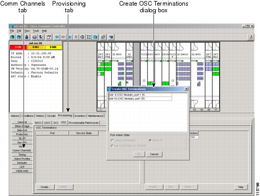
ステップ 5![]() Create OSC Terminations ダイアログボックスで、OSC 終端を作成するポートを選択します。複数のポートを選択するには、Shift キー(ポート範囲を選択します)または Ctrl キー(複数のポートを個別に選択します)を押します。
Create OSC Terminations ダイアログボックスで、OSC 終端を作成するポートを選択します。複数のポートを選択するには、Shift キー(ポート範囲を選択します)または Ctrl キー(複数のポートを個別に選択します)を押します。
(注) DWDM ノード上の OSC は、個別の OC3/STM1 チャネルを使って、ONS 15454 DCC 終端に使用される Section Data Communications Channel(SDCC; セクション データ通信チャネル)を転送します。
ステップ 6![]() Layer 3 ボックスで、次のいずれかを実行します。
Layer 3 ボックスで、次のいずれかを実行します。
•![]() IP ボックスのみをオンにする:LDCC が ONS 15454 と他の ONS ノード間にあり、ONS ノードのみがネットワークに存在する場合。LDCC は Point-to-Point Protocol(PPP)を使用します。
IP ボックスのみをオンにする:LDCC が ONS 15454 と他の ONS ノード間にあり、ONS ノードのみがネットワークに存在する場合。LDCC は Point-to-Point Protocol(PPP)を使用します。
•![]() IP および OSI ボックスをオンにする:LDCC が ONS 15454 と他の ONS ノード間にあり、OSI プロトコル スタックを使用しているサード パーティ製の NE が同じネットワーク上に存在する場合。LDCC は PPP を使用します。
IP および OSI ボックスをオンにする:LDCC が ONS 15454 と他の ONS ノード間にあり、OSI プロトコル スタックを使用しているサード パーティ製の NE が同じネットワーク上に存在する場合。LDCC は PPP を使用します。
ステップ 7![]() OSI をオンにしている場合、次の作業を行います。IP のみをオンにした場合は、ステップ 8 に進みます。
OSI をオンにしている場合、次の作業を行います。IP のみをオンにした場合は、ステップ 8 に進みます。
–![]() ESH:End System Hello(ESH)の伝播頻度を設定します。ES NE は ESH を送信して、他の ES および IS にサービスする NSAP を通知します。デフォルトは 10 秒です。範囲は 10~1000 秒です。
ESH:End System Hello(ESH)の伝播頻度を設定します。ES NE は ESH を送信して、他の ES および IS にサービスする NSAP を通知します。デフォルトは 10 秒です。範囲は 10~1000 秒です。
–![]() ISH:Intermediate System Hello PDU の伝播頻度を設定します。IS NE は ISH を他の ES および IS に送信して、サービスする IS NET を通知します。デフォルトは 10 秒です。範囲は 10~1000 秒です。
ISH:Intermediate System Hello PDU の伝播頻度を設定します。IS NE は ISH を他の ES および IS に送信して、サービスする IS NET を通知します。デフォルトは 10 秒です。範囲は 10~1000 秒です。
–![]() IIH:Intermediate System to Intermediate System Hello PDU の伝播頻度を設定します。IS-IS Hello PDU は IS 間の隣接性を確立、維持します。デフォルトは 3 秒です。範囲は 1~600 秒です。
IIH:Intermediate System to Intermediate System Hello PDU の伝播頻度を設定します。IS-IS Hello PDU は IS 間の隣接性を確立、維持します。デフォルトは 3 秒です。範囲は 1~600 秒です。
–![]() Metric:LAN サブネットで送信するパケットのコストを設定します。IS-IS プロトコルはコストを使用して最短のルーティング パスを算出します。LAN サブネットのデフォルトの Metric コストは 20 です。通常、この値を変更することはありません。
Metric:LAN サブネットで送信するパケットのコストを設定します。IS-IS プロトコルはコストを使用して最短のルーティング パスを算出します。LAN サブネットのデフォルトの Metric コストは 20 です。通常、この値を変更することはありません。
ステップ 8![]() Finish をクリックします。ポートが自動的にイン サービス状態になります。ネットワークの OSC 接続が隣接ノード間で作成されるまでの間、次のアラームが表示される場合があります。
Finish をクリックします。ポートが自動的にイン サービス状態になります。ネットワークの OSC 接続が隣接ノード間で作成されるまでの間、次のアラームが表示される場合があります。
•![]() OSCM または OSC-CSM カード上の SDCC Termination Failure アラーム
OSCM または OSC-CSM カード上の SDCC Termination Failure アラーム
•![]() OSCM または OSC-CSM カードの OC-3 ポート(ポート #1)上の LOS-P アラーム
OSCM または OSC-CSM カードの OC-3 ポート(ポート #1)上の LOS-P アラーム
•![]() OPT-BST または OSC-CSM カード上の OPWR-LFAIL アラーム
OPT-BST または OSC-CSM カード上の OPWR-LFAIL アラーム
(注) OSC 終端が作成されると、回線ポートがイン サービス状態になり、スパン電力レベルがチェックされます。
ステップ 9![]() 「G39 OSCM および OSC-CSM の送信電力の確認」に進みます。
「G39 OSCM および OSC-CSM の送信電力の確認」に進みます。
NTP-G39 OSCM および OSC-CSM の送信電力の確認
この手順では、ONS 15454 Optical Service Channel Module(OSCM; 光サービス チャネル モジュール)と Optical Service Channel + Combiner Separator Module(OSC-CSM; 光サービス チャネル + コンバイナ/セパレータ モジュール)の送信電力を確認します。 |
|
ステップ 1![]() DWDM ケーブル接続をプロビジョニングするノードで 「G46 CTC へのログイン」 を実行します。すでにログインしている場合は、ステップ 2 に進みます。
DWDM ケーブル接続をプロビジョニングするノードで 「G46 CTC へのログイン」 を実行します。すでにログインしている場合は、ステップ 2 に進みます。
ステップ 2![]() ノード ビューのシェルフ図で、OSCM カードまたは OSC-CSM カードをダブルクリックします。
ノード ビューのシェルフ図で、OSCM カードまたは OSC-CSM カードをダブルクリックします。
ステップ 3![]() Maintenance > ALS タブをクリックします。
Maintenance > ALS タブをクリックします。
ステップ 4![]() ALS Mode ドロップダウン リストから、 Disable を選択します。 Apply をクリックします。
ALS Mode ドロップダウン リストから、 Disable を選択します。 Apply をクリックします。
ステップ 5![]() Provisioning > Optical Line > Parameters タブをクリックします。
Provisioning > Optical Line > Parameters タブをクリックします。
ステップ 6![]() 取り付けられているカードの Power カラムの値を記録します。
取り付けられているカードの Power カラムの値を記録します。
•![]() OCS-CSMカード:Port 7 TX Output OSC
OCS-CSMカード:Port 7 TX Output OSC
•![]() OCSM カード:Port 3 TX Output OSC
OCSM カード:Port 3 TX Output OSC
ステップ 7![]() ステップ 6の電力値と 表3-3 の電力値を比較します(取り付けられたカードによって異なります)。
ステップ 6の電力値と 表3-3 の電力値を比較します(取り付けられたカードによって異なります)。
|
|
|
|
|---|---|---|
|
|
|
|
a. b. c. |
ステップ 6に記録されている電力値が -5 dBm と等しいか確認します。 |
a. b. c. |
ステップ 8![]() OSCM または OSC-CSM電力レベルが ステップ 7 に指定された範囲内にない場合は、次のステップを実行します。指定された範囲内にある場合は、ステップ 9 に進みます。
OSCM または OSC-CSM電力レベルが ステップ 7 に指定された範囲内にない場合は、次のステップを実行します。指定された範囲内にある場合は、ステップ 9 に進みます。
a.![]() Maintenance > ALS の順序でタブをクリックします。ALS コマンドで OSRI がオフに設定されていることを確認します。
Maintenance > ALS の順序でタブをクリックします。ALS コマンドで OSRI がオフに設定されていることを確認します。
b.![]() 光接続箇所を清掃します。「G115 ファイバ コネクタのクリーニング」を参照してください。
光接続箇所を清掃します。「G115 ファイバ コネクタのクリーニング」を参照してください。
ステップ 9![]() Maintenance > ALS タブをクリックします。
Maintenance > ALS タブをクリックします。
ステップ 10![]() ALS Mode ドロップダウン リストから、 AutoRestart を選択します。 Apply をクリックします。
ALS Mode ドロップダウン リストから、 AutoRestart を選択します。 Apply をクリックします。
ステップ 11![]() 第 4 章「ノード受け入れテストの実行」 に記載されているノードの受け入れテストの手順に進みます。
第 4 章「ノード受け入れテストの実行」 に記載されているノードの受け入れテストの手順に進みます。
(注) MXP/TXP カードや DWDM カードに接続されている光ファイバ ケーブルを圧迫しないように注意してください。ファイバ ブーツが付属されていないものもあります。
ステップ 1![]() 前面扉をシェルフ アセンブリのヒンジに挿入します。
前面扉をシェルフ アセンブリのヒンジに挿入します。
ステップ 2![]() アース ストラップの終端ラグ(72-3622-01)の一端を扉の内側のメイル スタッドに取り付けます。オープンエンド レンチを使用して、#6 ケプナット(49-0600-01)を取り付けて固定します(図3-19)。
アース ストラップの終端ラグ(72-3622-01)の一端を扉の内側のメイル スタッドに取り付けます。オープンエンド レンチを使用して、#6 ケプナット(49-0600-01)を取り付けて固定します(図3-19)。
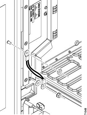
ステップ 3![]() アース ストラップの他端をファイバ ガイドの長いほうのネジに取り付けます。
アース ストラップの他端をファイバ ガイドの長いほうのネジに取り付けます。
c.![]() オープンエンド レンチを使用して、#4 ケプナット(49-0337-01)を終端ラグに取り付けて固定します。
オープンエンド レンチを使用して、#4 ケプナット(49-0337-01)を終端ラグに取り付けて固定します。
(注) トラフィック(回線)カードの干渉を防ぐため、ドアが開いた状態でアース ストラップが水平になるように配置します。アース ストラップを水平な位置に移動するには、ケプナットを固定する前に終端ラグを左回りに回します。
ステップ 5![]() プラス ネジ用ドライバを使って、ケーブル配線路チャネルのネジを挿入して固定します。
プラス ネジ用ドライバを使って、ケーブル配線路チャネルのネジを挿入して固定します。
図3-20 に前面扉とアース ストラップを取り付けたシェルフ アセンブリの例を示します。
図3-20 扉のアース ストラップ改良キットを取り付けたシェルフ アセンブリ
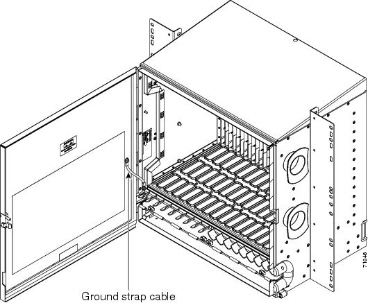
(注) ONS 15454 には、前面扉の鍵の開閉のため、ピン付きの六角キーが付属しています。キーを左回りに回転すると扉がロック解除され、右回りに回転するとロックされます。
 フィードバック