Overview of Cisco CW9800L Wireless Controller

The Cisco CW9800L Wireless Controller is the next-generation, low-end controller that provides a significant boost in performance and features. The CW9800L controller supports up to 8 Gbps throughput, 500 APs, and 10,000 clients. It is built upon an Intel Icelake-D CPU running Cisco IOS XE.

The CW9800L targets a hybrid-redundancy solution, making it ideal for distributed deployments. One or two CW9800L units can be installed at a remote-site or branch office, with backup provided through FlexConnect over the WAN to a Wireless Controller located at a central site.

For more information about features and benefits, see the Cisco CW9800L Wireless Controller Data Sheet.

Figure 1. Cisco CW9800L Wireless Controller

Summary of Cisco CW9800L Wireless Controller features

Table 1. Cisco CW9800L Wireless Controller features

Feature

Description

Chassis Height

One rack-unit (1RU)

Throughput

Up to 10 Gbps

Number of APs supported

500

Number of clients supported

10,000

Processor

Intel Icelake-D LCC (8-core, 2 GHz)

Memory Options

  • Control/Data Plane Memory: 32GB DDR4 on-board with ECC

  • Boot Flash: 512Mb Serial NOR

  • Bulk Flash: 32GB on-board pSLC eMMC (with optional eUSB support)

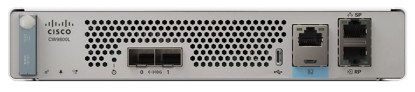
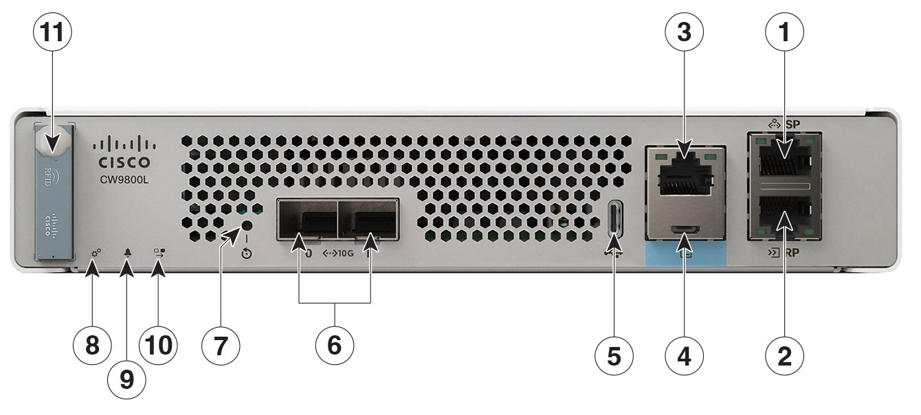
Redundancy, Service Ports

1x 1GE Cu Service/Management port

Data Ports

1x 1G/10G Fiber (SFP+)

Storage Temperature

–13° F to 158° F (–25° C to 70° C)

Operating Temperature

0° C to 40° C standard, 0° C to 50° C short-term (sea level)

Note


The maximum temperature is derated by 1.0° C for every 1000 ft (305 m) of altitude above sea level.

Storage Humidity

0% to 95% RH non-condensing

Operating Humidity

5% to 90% RH non-condensing

Operational Altitude

0 to 10,000 ft (3048m) at 30° C
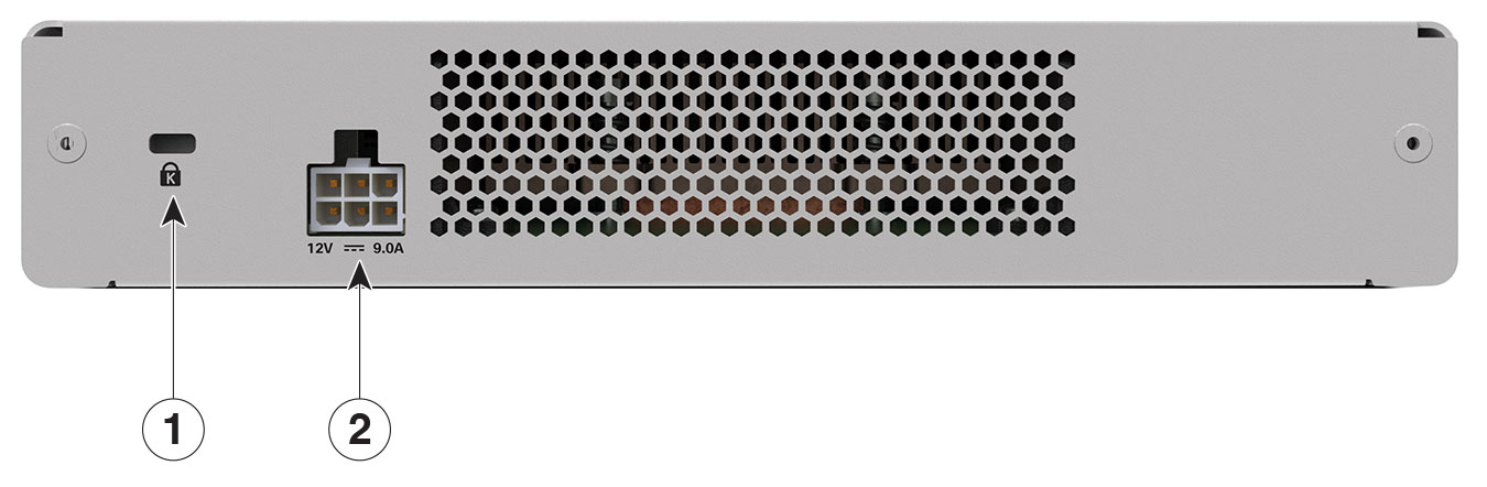
Power Adapter

110W single 12V output adapter (C9800-AC-110W)


Note


The CW-ACC-MEM-32G 32GB memory module is an optional component that can only be ordered alongside the Cisco CW9800L Wireless Controller and cannot be added or ordered separately afterward. If your unit includes this optional memory module and requires a Return Merchandise Authorization (RMA), it is essential to remove the CW-ACC-MEM-32G module before returning the WLC to the depot. The replacement unit you receive from the RMA depot will not contain a memory module. Cisco Technical Assistance Center (TAC) will provide guidance during this removal process.


Platform Components

Cisco CW9800L Wireless Controller front panel

Figure 2. Cisco CW9800L Wireless Controller front panel view
Table 2. Cisco CW9800L Wireless Controller front panel components

1

Service Port (SP) (RJ-45) for out-of-band management

2

Redundancy Port (RP) (RJ-45)

Note


The redundancy ports can be connected back to back or via an L2 switch.

3

CPU console port, which is an RJ-45 RS-232 and micro-B USB serial console port. The default RJ-45 serial port settings are 9600, N, 8, 1. The boot-loader supports baud rates of 1200, 2400, 4800, 9600, 19200, 38400, 57600, and 115200. A default baud-rate recovery mechanism is not available; however, the bootloader ensures that the stored baud rate setting matches one of the allowed values before setting the baud rate. If a nonstandard value is detected, the baud rate will default to 9600.

Micro-B USB serial connection takes precedence over RJ-45 when both connections are made.

Note


If the Micro-B USB console port is used, the CPU console port that supports RJ-45 connector is ignored. That is, only one of the two ports are ever active.

4

Micro USB console port that can be used to perform software updates in addition to the already available transfer modes, namely HTTP, TFTP, FTP, and SFTP.

Note


If you connect both the Micro USB console port and the CPU console port, then USB port takes precedence and the CPU console port is ignored as only one of the two ports are ever active.

5

Type C 3.0 USB port used to perform software updates in addition to already available transfer mode, namely HTTP, TFTP, FTP, and SFTP.

6

1x1/10G SFP+ ports. This port supports speeds of 1G and 10G.

7

Reset button

  • Pushing the Reset button for less than 10 seconds reloads the controller.

  • Pushing the Reset button for more than 10 seconds erases the startup configuration in NVRAM of the controller.

8

System LED that displays power-up and boot status.

9

Alarm LED indicates alarm staus or error states. The status or error is posted on the console screen.

10

High Availability LED that indicates status of High Availability link.

11

RFID stores identification information about the unit that can be accessed with a reader.

Front panel LEDs: definitions of states

Table 3. System LED indicators

Color

Description

Green

IOS has boot complete

Blinking Green

IOS boot in progress

Amber

System crash

Blinking amber

Secure boot failure

Off

ROMMON boot

Table 4. Alarm LED indicators

Color

Description

Amber

ROMMON boot and system boot up

Blinking amber

Temperature error and secure boot failure

Slow blink amber

Booted with high availability standby

Fast blink amber

High availability maintenance

Table 5. High availability LED indicators

Color

Description

Green

High availability active

Blinking Green

High availability standby

Solid amber

Peer not found

Slow blinking amber

Booted with high availablity standby cold

Fast blink amber

High availability maintenance

Off

High availability disable

Table 6. SFP LED indicators

Color

Description

Solid green

Indicates the signal detected and enabled by software

Solid amber

Indicates the loss of signal

Off

Not configured and enabled by software

Table 7. Port LED indicators

Color

Description

Solid green

Indicates link

Flashing green

Indicates activity


Note


  • The Cisco CW9800L Wireless Controller has an external power adapter.

  • The Alarm Bell LED is illuminated red, if the 10-G uplink ports are not connected to the switch. This does not mean a system or hardware failure. When the interfaces are disabled in the controller, the red light remains off even when the controller is not connected.


Cisco CW9800L Wireless Controller rear panel

Figure 3. Cisco CW9800L Wireless Controller rear panel view
Table 8. Cisco CW9800L Wireless Controller rear panel components

1

Attachment slot for Kensington style cable lock.

2

Connection point for external 110W, single output 12VDC power adapter (C9800-AC-110W).