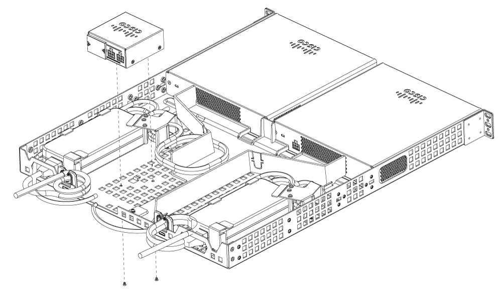
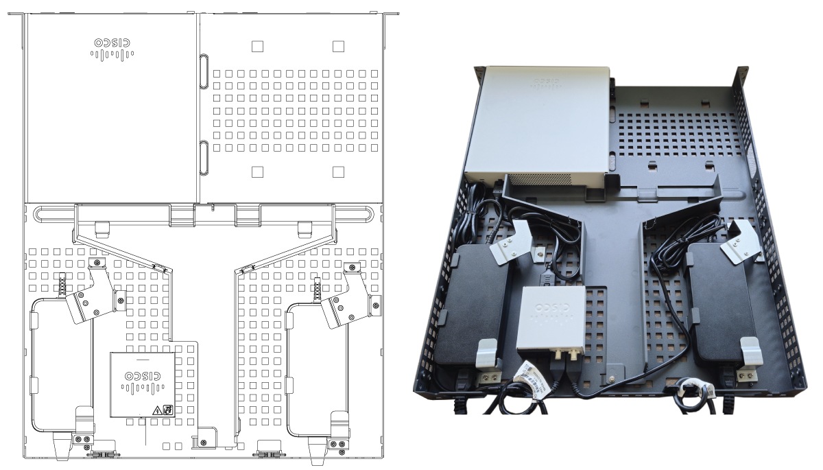
Redundant power supply module
This table describes the components used with the optional Redundant Power Supply (RPS) module for the CW9800L hardware platform, operating as either a Wireless Controller or Campus Gateway.
|
Part number |
Description |
|---|---|
|
C9800-AC-110W |
110W AC power supply (ordered with device) |
|
CW9800L-RPS
|
CW9800L RPS kit
|
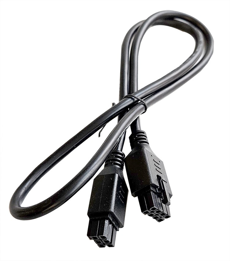
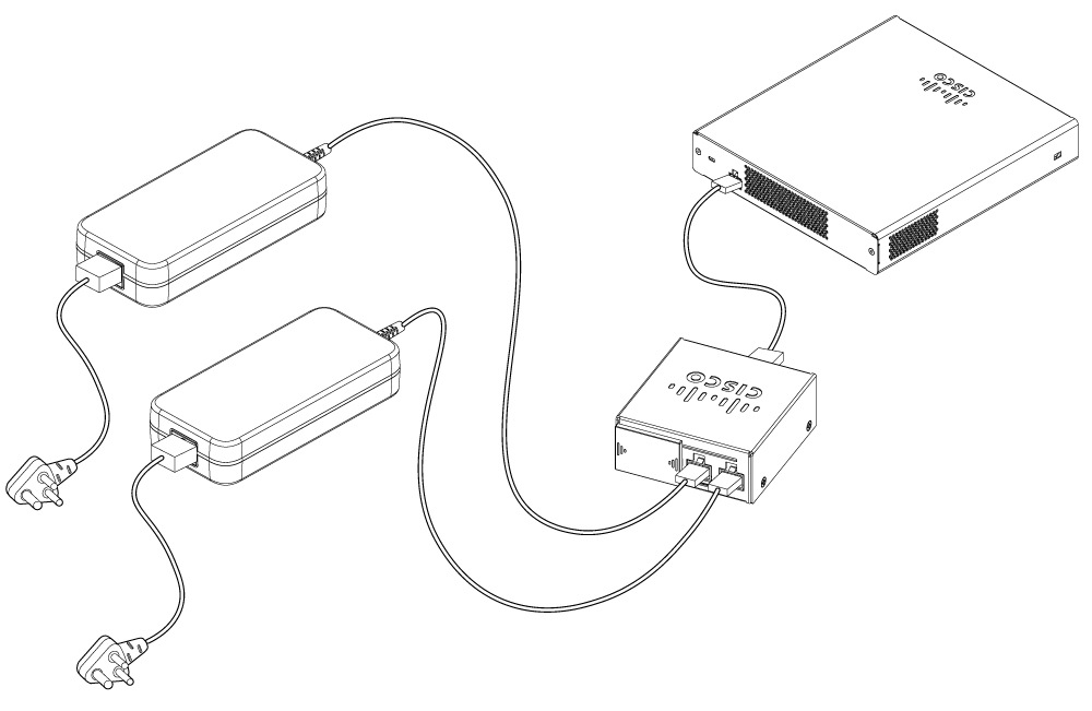
The RPS takes power inputs from two redundant PSUs and outputs a single power feed to the kit.


 Feedback