Mount the CW9800L
This section describes the various mounting options for the controller:
Mount the device on desktop or shelf
Before mounting the CW9800L on a desktop or shelf, install the rubber feet located in accessory kit shipped with the device.
To install the rubber feet to the device, follow these steps:
Procedure
|
Step 1 |
Locate the rubber feet on the black adhesive strip that is shipped with the device. 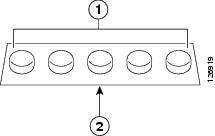
|
||||
|
Step 2 |
Place the box upside down, on a smooth, flat surface. |
||||
|
Step 3 |
Peel off the rubber feet from the black adhesive strip and press them adhesive-side down into the circular recesses in the bottom four corners of the device, see the figure below: 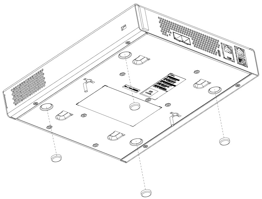
|
||||
|
Step 4 |
Place the device right-side up on a flat, smooth, secure surface. |
||||
|
Step 5 |
Connect the interface cables. |
Mount the device on a wall
 Note |
Do not wall-mount the device with its front panel facing up. Following safety regulations, wall-mount the device with its front panel facing down or to the side to prevent airflow restriction and to provide easier access to the cables. |
 Warning |
Read the wall-mounting carefully before beginning installation. Failure to use the correct hardware or to follow the correct procedures could result in a hazardous situation to people and damage to the system. Statement 378. |
Note |
Wall mounting screws are not supplied. Installer must supply proper screws in accordance with local codes. Controller wall mount holes located on the bottom of the enclosure fit standard #6 or M3 Pan Head screw. The type of screw used to mount to wall should follow local guidelines for wall type and material. |
To mount the device on a wall using mounting screws, follow these steps:
Procedure
|
Step 1 |
Mark the location of the mounting screws on the wall. Use the mount hole locations on the back of the device for placement of the mounting screws. Mounting screw spacing is 6 1/8 inch (155.4 mm). |
||
|
Step 2 |
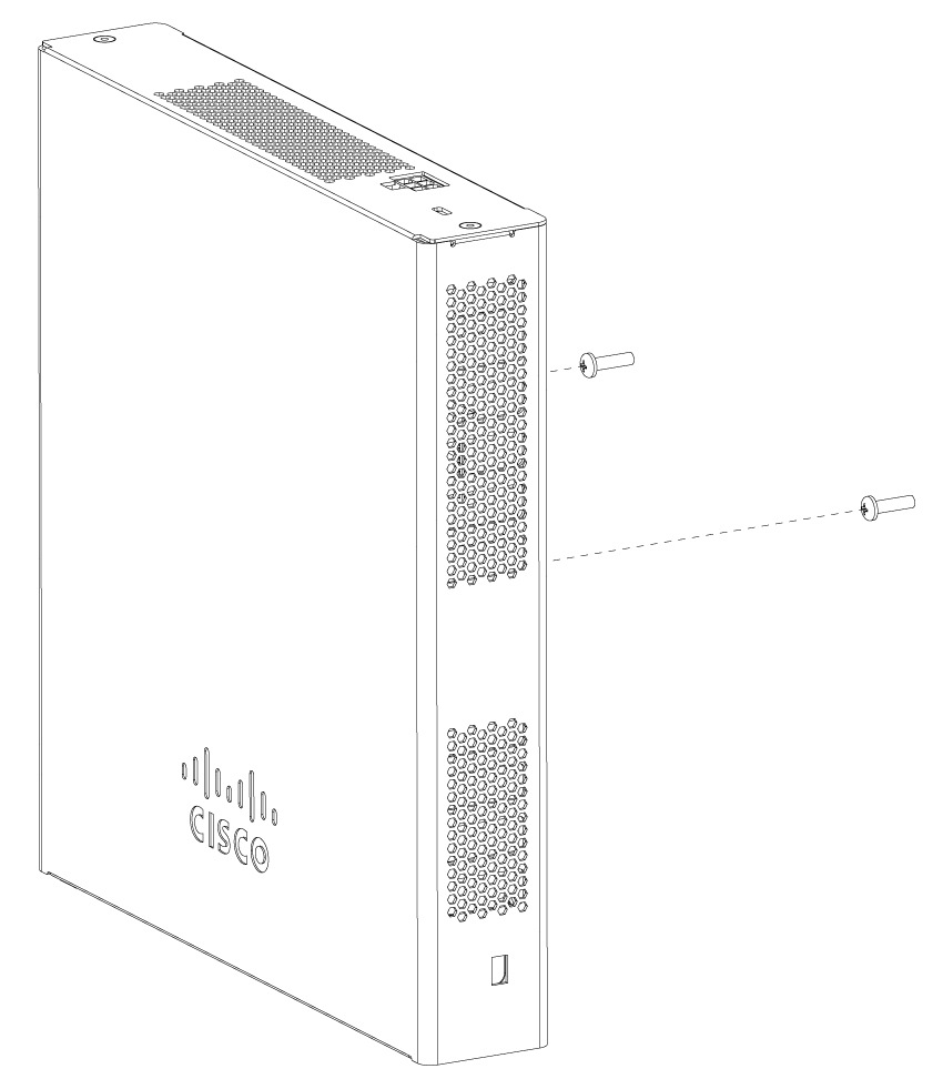
Install two screws and tighten until the top of the screws are 1/8 inch (3 mm) from the wall (leaving enough room for the back panel to slide onto the screws firmly). |
||
|
Step 3 |
Place the device onto the mounting screws and slide it down until it locks into place, as shown in figure below:
|
||
|
Step 4 |
After the device is mounted on the wall, perform these tasks to complete the installation
|
||
|
Step 5 |
For wireless controller configuration instructions about using the CLI setup program, see the Minimum Bootstrap CLI configuration for Catalyst 9800. For Campus Gateway configuration instructions, see the Campus Gateway Overview and Specifications page. |
Rack mounting the device
Warning |
To prevent bodily injury when mounting or servicing this unit in a rack, you must take special precautions to ensure that the system remains stable. These guidelines ensure your safety.
Statement 1006 |
Warning |
Take care when connecting units to the supply circuit so that wiring is not overloaded. Statement 1018. |
To mount the device in a 19-inch equipment rack, you can order an optional Rack Mount kit CW9800L-RMNT= Cisco CW9800L Wireless Controller Rack Mount Tray.
The rack-mount tray is designed for 19 racks and uses one rack-unit space. To rack-mount the device, perform these steps:
Procedure
|
Step 1 |
Remove the four rubber feet if previously installed. |
||
|
Step 2 |
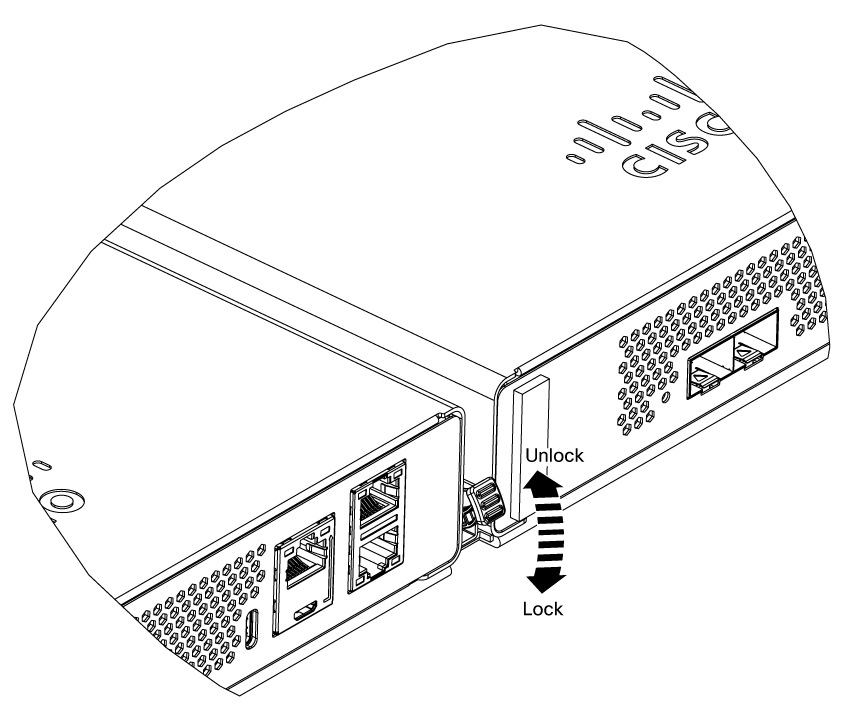
Ensure that the latch at the front center of the tray is in the upward position. Position the Cisco CW9800L hardware platform on one half of the tray with the I/O ports toward the front of the tray. The front end of the box should hang about a half inch off the front of the tray. This positioning should align the bottom of it with the 4 hooks in the tray, and allow the box to sit flat on the bottom of the tray. Ensuring that the CW9800L is fully down flat on the bottom of the tray, slide controller it to the rear until it hits a stop. This will occur when the front of it is approximately flush with the front of the rack mount tray. Push the handle on the latch at the front center of the tray down to lock the box in place. Repeat if desired for a second CW9800L on the other side of the tray. 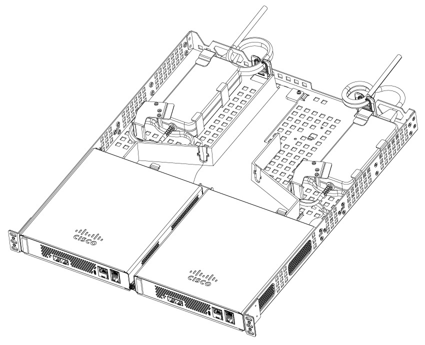
|
||
|
Step 3 |
Place each power adapter, with the AC power cord at the rear of the tray, over against the two vertical L-shaped tabs at the left as shown. Secure each adapter body to the tray by installing the two sheet metal brackets to the tray as shown with two screws each. 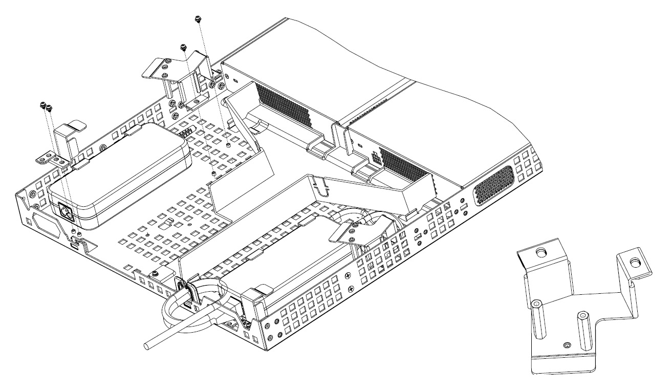
|
||
|
Step 4 |
Route the power adapter DC output cords to the CW9800L power connectors. Bundle and secure any excess cable neatly. On the right side of the tray (viewed from the rear), remove the break-out tab on the plastic air baffle to allow the cord to be routed to the CW9800L input power connector. Bend the tab back and forth a few times and break it out of its slot. |
||
|
Step 5 |
Using the hardware supplied, mount the rack mount tray to the rack according to these figures. 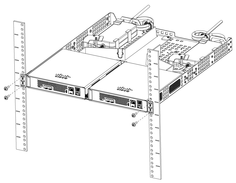
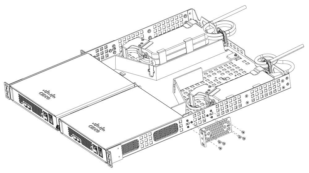
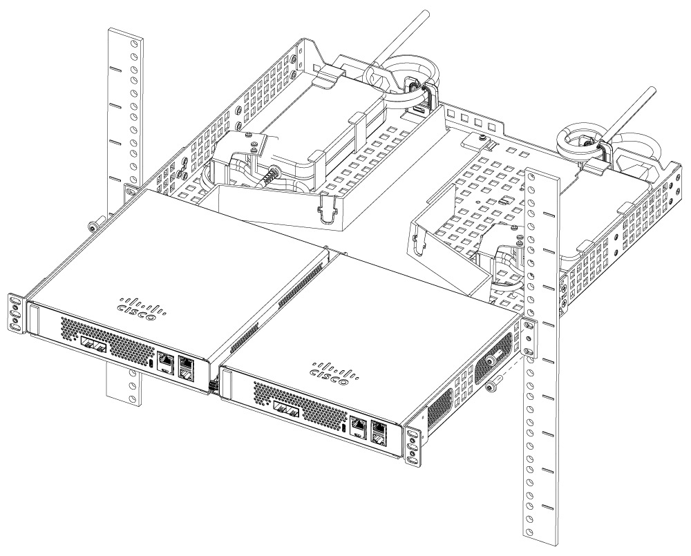
To remove the chassis from the rack, remove the screws that attach the chassis to the rack, and then remove the chassis. |

 Feedback