Cisco CW9800L Wireless Controller Data Sheet
Available Languages
Bias-Free Language
The documentation set for this product strives to use bias-free language. For the purposes of this documentation set, bias-free is defined as language that does not imply discrimination based on age, disability, gender, racial identity, ethnic identity, sexual orientation, socioeconomic status, and intersectionality. Exceptions may be present in the documentation due to language that is hardcoded in the user interfaces of the product software, language used based on RFP documentation, or language that is used by a referenced third-party product. Learn more about how Cisco is using Inclusive Language.
The Cisco CW9800L Wireless Controller brings wireless management to small and medium wireless networks. It can manage up to 500 Access Points (APs) and 10,000 clients while providing flexibility and scalability in building a secure and assured wireless network.
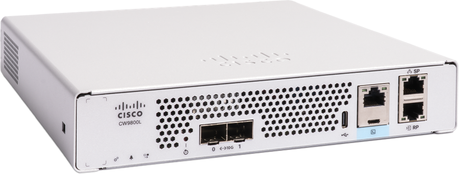
The Cisco CW9800L Wireless Controller brings advanced performance, security, and simplicity to small and medium-sized wireless networks. It supports up to 500 APs and 10,000 clients delivering robust, future-ready Wi-Fi for handling the latest devices, cloud-based applications, and IoT demands with ease. With enterprise-grade features in a compact form factor, it is ideal for growing businesses, educational campuses, or remote branches.
Powered by Cisco IOS® XE, the Cisco CW9800L enables seamless integration with Cisco Catalyst Center for AI-driven analytics, enhanced troubleshooting, and network automation. Security is built in, with support for WPA3, Encrypted Traffic Analytics, and Software-Defined Access, helping to safeguard users and data.
Cloud monitoring, accessible via the Meraki dashboard, provides unified visibility for easy management and troubleshooting. With application hosting and modular design, it supports next-generation use cases while maximizing investment.
The Cisco CW9800L is the ideal choice for organizations seeking intelligent, secure, and future-proofed wireless connectivity delivering enterprise innovation at the right scale for your needs.
Table 1. Features overview
| Feature |
Description |
| Chassis Height |
One rack-unit (1 RU) |
| Processor |
Intel Icelake-D LCC (8-core, 2 GHz) |
| Maximum number of access points |
500 |
| Maximum number of clients |
10000 |
| Maximum throughput |
Up to 10 Gbps |
| Maximum WLANs |
4096 |
| Maximum VLANs |
4096 |
| Maximum Site Tags |
250 |
| Maximum Flex APs per site |
400 |
| Maximum policy tags |
4096 |
| Maximum RF tags |
250 |
| Maximum RF profiles |
500 |
| Maximum policy profiles |
4096 |
| Maximum Flex profiles |
250 |
| Fixed uplinks |
2x 1G/10G SFP+ |
| Redundant power supply (Optional) |
CW9800L-RPS= (Dual-input DC power sources to single adapter for power redundancy) |
| Maximum power consumption |
90 W (with 4.5 W USB load) |
| Deployment modes |
Centralized (local), Distributed Branch (Cisco FlexConnect®), SD-Access Wireless (fabric) |
| Form factor |
8.5” x 9.24” x 1.58” (216 mm * 234.7 mm * 40.2 mm) |
Enhanced Performance, Capacity, and Operational Efficiency
The Cisco CW9800L Wireless Controller significantly elevates the capabilities of wireless infrastructure, offering increased performance and double the capacity compared to the base C9800-L model. It supports up to 500 access points and 10,000 clients, with up to 10 Gbps backhaul throughput, making it ideal for small to medium deployments.
Beyond capacity, the CW9800L is designed for operational efficiency, operating up to 10 dB quieter than its predecessor. Its compact 1 RU form factor, combined with a dedicated rack shelf (CW9800L-RMNT=) that allows two units to occupy a single rack unit, optimizes space. This blend of higher capacity and reduced operational footprint provides substantial business value through improved network handling and lower operational costs.
● Twice the capacity and increased performance over base C9800-L
● Supports up to 500 APs, 10,000 clients, and 10 Gbps of throughput
● Up to 10 dB quieter operation for flexible deployment
● 1 RU design with dual-unit rack shelf option
The CW9800L extends its value through advanced features that bolster flexibility and reliability. It supports app hosting containers, enabling customers to deploy custom applications directly on the controller when ordered with the additional 32 GB storage option. This capability enhances network programmability and allows for tighter integration of third-party services.
The CW9800L offers a redundant power option (CW9800L-RPS=), ensuring continuous operation and minimizing service interruptions.
The Cisco Wireless 9800L Wireless Controller is available as a single SKU appliance:
● CW9800L
It supports Cisco Access Points from the following generations: Wi-Fi 5 Wave 2 (802.11ac Wave 2), Wi-Fi 6/6E (802.11ax), and Wi-Fi 7 (802.11be)
Image Specifications
The Cisco CW9800L Wireless Controller requires minimum 17.18.2 IOS-XE release.
Physical Dimensions
Table 2. Specifications of Cisco CW9800L WLC
| Dimension |
Value |
| Width |
8.5 in (216 mm) |
| Depth |
9.24 in (235 mm) |
| Height |
1.58 in (40 mm) |
| Weight |
4.6 lb (2.1 kg) |
Product Components
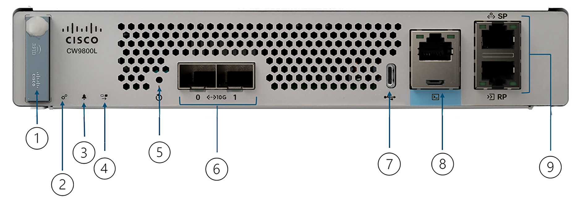
Front Panel
Table 3. Front Panel Components
| Label |
Description |
| 1 |
RFID Tag (Optional) |
| 2 |
System LED |
| 3 |
Alarm LED |
| 4 |
High Availability LED |
| 5 |
Reset Button |
| 6 |
2x 1/10G SFP ports |
| 7 |
USB 3.0 port |
| 8 |
Micro USB and RJ45 console ports |
| 9 |
RJ-45 Service Port (SP) and Redundancy Port (RP) |
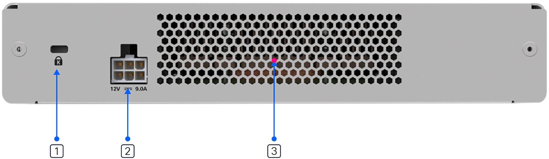
CW9800L Back Panel Components
Table 4. Back Panel Components
| Label |
Description |
| 1 |
Kensington lock |
| 2 |
Power adapter |
| 3 |
Ventilation |
Table 5. Ports and their Purpose
| Port |
Description |
| 1x RJ-45 console port |
Console port for out-of-band management. |
| 1x Micro USB console port |
Console port for out-of-band management. |
| 1x USB 3.0 port Type C |
USB 3.0 port for plugging in external memory. |
| 1x RJ-45 management port |
Management port used for out-of-band management. Also known as the service port. |
| 1x RJ-45 redundancy port |
Redundancy port used for SSO. |
| 2x SFP+ 10G fiber ports |
Ports used for sending and receiving traffic between access points and controller, northbound traffic, in-band management traffic, and wireless client traffic. Must be connected to the switch. |
Front Panel LEDs
Table 6. Definition of Front Panel LED State
| LED |
Color |
Function |
| System |
Solid Green |
Indicates that the IOS has completed booting. |
| Blinking Green |
Indicates that the IOS boot process is in progress. |
|
| Solid Amber |
Indicates a system crash. |
|
| Blinking Amber |
Indicates a secure boot failure. |
|
| Off |
Indicates the system is in ROMMON boot mode. |
|
| Alarm (ALARM / ALM) LED |
Solid Green |
Indicates that ROMMON boot is complete. |
| Blinking Green |
Indicates that a system image upgrade is in progress. |
|
| Solid Amber |
Indicates that ROMMON boot and system boot up are active. |
|
| Blinking Amber |
Indicates a temperature error or secure boot failure. |
|
| Off |
HA Disable |
|
| HA LED |
Solid Green |
HA Active |
| Blinking Green |
HA Standy Hot |
|
| Solid Amber |
Peer not found |
|
| Slow Blinking Amber |
Booted w/HA Standby Cold |
|
| Fast Blinking Amber |
HA Maintenance |
|
| Red |
WLC is powered on and loading bootstrap firmware (along with System LED Green and Alarm LED Solid Amber) |
|
| SFP LED |
Solid Green |
Indicated the Signal Detected and enable by Software |
| Solid Amber |
Indicated the Loss of Signal |
|
| Off |
Not Configured and not enable by software |
|
| Console |
Solid Green (Right LED on RJ45) |
USB Console Active |
| Solid Green (Left LED on RJ45) |
RJ-45 Console Active |
|
| SP/RP LEDs |
Off |
No linkup |
| Solid Green (Right LED on RJ45) |
Linkup |
|
| Blinking Green (Left LED on RJ45) |
Activity |
Table 7. Specifications
|
|
Specification |
|
| Wireless |
IEEE 802.11a, 802.11b, 802.11g, 802.11d, WMM/802.11e, 802.11h, 802.11n, 802.11k, 802.11r, 802.11u, 802.11w, 802.11ac Wave1 and Wave2, 802.11ax, 802.11be |
|
| Wired, switching, and routing |
IEEE 802.3 10BASE-T, IEEE 802.3u 100BASE-TX, 1000BASE-T, 1000BASE-SX, 1000-BASE-LH, IEEE 802.1Q VLAN tagging, IEEE 802.1AX Link Aggregation, 802.3ae |
|
| Data Standards Requests For Comments (RFCs) Security standards |
● RFC 768 User Datagram Protocol (UDP)
● RFC 791 IP
● RFC 2460 IPv6
● RFC 792 Internet Control Message Protocol (ICMP)
● RFC 793 TCP
● RFC 826 Address Resolution Protocol (ARP)
● RFC 1122 Requirements for Internet Hosts
● RFC 1519 Classless Interdomain Routing (CIDR)
● RFC 1542 Bootstrap Protocol (BOOTP)
● RFC 2131 Dynamic Host Configuration Protocol (DHCP)
● RFC 5415 Control and Provisioning of Wireless Access Points (CAPWAP) Protocol
● RFC 5416 CAPWAP Binding for 802.11
● IEEE 802.11i (WPA2, RSN)
● Wi-Fi Protected Access 3 (WPA3)
● RFC 1321 MD5 Message-Digest Algorithm
● RFC 1851 Encapsulating Security Payload (ESP) Triple DES (3DES) Transform
● RFC 2104 HMAC: Keyed-Hashing for Message Authentication
● RFC 2246 TLS Protocol Version 1.0
● RFC 2401 Security Architecture for the Internet Protocol
● RFC 2403 HMAC-MD5-96 within ESP and AH
● RFC 2404 HMAC-SHA-1-96 within ESP and AH
● RFC 2405 ESP DES-CBC Cipher Algorithm with Explicit IV
● RFC 2407 Interpretation for Internet Security Association Key Management Protocol (ISAKMP)
● RFC 2408 ISAKMP
● RFC 2409 Internet Key Exchange (IKE)
● RFC 2451 ESP CBC-Mode Cipher Algorithms
● RFC 3280 Internet X.509 Public Key Infrastructure (PKI) Certificate and Certificate Revocation List (CRL) Profile
● RFC 4347 Datagram Transport Layer Security (DTLS)
● RFC 5246 TLS Protocol Version 1.2
● RFC 8446 TLS Protocol Version 1.3
|
|
| Encryption |
● Advanced Encryption Standard (AES): Cipher Block Chaining (CBC), Counter with CBC-MAC (CCM), Counter with CBC Message Authentication Code Protocol (CCMP)
● Data Encryption Standard (DES): DES-CBC, 3DES
● Secure Sockets Layer (SSL) and Transport Layer Security (TLS): RC4 128-bit and RSA 1024-and 2048-bit
● DTLS: AES-CBC
● IPsec: DES-CBC, 3DES, AES-CBC (Supported only for FIPS use cases)
|
|
| Authentication, Authorization, and Accounting (AAA) |
● IEEE 802.1X
● RFC 2548 Microsoft Vendor-Specific RADIUS Attributes
● RFC 2716 Point-to-Point Protocol (PPP) Extensible Authentication Protocol (EAP)-TLS
● RFC 2865 RADIUS Authentication
● RFC 2866 RADIUS Accounting
● RFC 2867 RADIUS Tunnel Accounting
● RFC 2869 RADIUS Extensions
● RFC 3576 Dynamic Authorization Extensions to RADIUS
● RFC 5176 Dynamic Authorization Extensions to RADIUS
● RFC 3579 RADIUS Support for EAP
● RFC 3580 IEEE 802.1X RADIUS Guidelines
● RFC 3748 Extensible Authentication Protocol (EAP)
● Web-based authentication
● TACACS support for management users
|
|
| Management |
● Simple Network Management Protocol (SNMP) v1, v2c, v3
● RFC 854 Telnet
● RFC 1155 Management Information for TCP/IP-based Internets
● RFC 1156 MIB
● RFC 1157 SNMP
● RFC 1213 SNMP MIB II
● RFC 1350 Trivial File Transfer Protocol (TFTP)
● RFC 1643 Ethernet MIB
● RFC 2030 Simple Network Time Protocol (SNTP)
● RFC 2616 HTTP
● RFC 2665 Ethernet-Like Interface Types MIB
● RFC 2674 Definitions of Managed Objects for Bridges with Traffic Classes, Multicast Filtering, and Virtual Extensions
● RFC 2819 Remote Monitoring (RMON) MIB
● RFC 2863 Interfaces Group MIB
● RFC 3164 Syslog
● RFC 3414 User-Based Security Model (USM) for SNMPv3
● RFC 3418 MIB for SNMP
● RFC 3636 Definitions of Managed Objects for IEEE 802.3 MAUs
● RFC 4741 Base NETCONF protocol
● RFC 4742 NETCONF over SSH
● RFC 6241 NETCONF
● RFC 6242 NETCONF over SSH
● RFC 5277 NETCONF event notifications
● RFC 5717 Partial Lock Remote Procedure Call
● RFC 6243 With-Defaults capability for NETCONF
● RFC 6020 YANG
● Cisco private MIBs
|
|
| Management interfaces |
● Web-based: HTTP/HTTPS
● Command-line interface: Telnet, Secure Shell (SSH) Protocol, serial port
● SNMP
● NETCONF
|
|
| Environmental conditions supported |
Operating temperature:
● 32° F to 104° F (0° C to 40° C)
Storage temperature:
● –13° F to 158° F (–25° C to 70° C)
Operating humidity:
● 5%-95% RH non-condensing
Storage humidity:
● 0%-95% RH non-condensing
Altitude:
● Operational altitude: 0 to 10,000 ft (3048 m) at 86° F/30° C
● Nonoperating altitude: TBD
Electrical input:
● AC input frequency range: 50 to 60 Hz
● AC input voltage: 100 to 240 VAC
Maximum power consumption:
● CW9800L max measured power = 90 W (with 4.5 W USB load)
Maximum heat dissipation:
● CW9800L: 307.2 Btu/hr (with 4.5 W USB load)
Sound power level measure:
● Normal up to 25.6C (78.8F): 29.5 bBA
● Elevated 26 to 39C (79-102F): 37.4 dBA
● High 40-49C (104-122F): 43.8 dBA
● Max 50C+ (122F+): 47.3 dBA
Power adapter:
● Input power: 100 to 240 VAC; 50/60 Hz
|
|
| Regulatory compliance |
Safety:
● UL/CSA 60950-1
● IEC/EN 60950-1
● AS/NZS 60950.1
● CAN/CSA-C22.2 No. 60950-1
|
|
| EMC - Emissions: |
Class A |
|
|
● FCC 47CFR15
● AS/NZS CISPR 22
● CISPR 22
● EN55022/EN55032 (EMI-1)
● ICES-003
● VCCI
● KN 32 (EMI-2)
● CNS-13438
|
|
|
| EMC – Emissions:
● EN61000-3-2 Power Line Harmonics (EMI-3)
● EN61000-3-3 Voltage Changes, Fluctuations, and Flicker (EMI-3)
|
||
Table 8. Supported SFPs
| Type |
Modules supported |
| 1G SFP |
GLC-TE GLC-LH-SMD GLC-SX-MMD |
| 10G SFP |
SFP-10G-SR SFP-10G-SR-S SFP-10G-LR SFP-10G-LR-S SFP-H10GB-CU2.5M SFP-H10GB-CU3M SFP-H10GB-CU5M SFP-H10GB-ACU7M SFP-H10GB-ACU10M Finisar-LR (FTLX1471D3BCL) Finisar-SR (FTLX8574D3BC) SFP-10G-AOC1M SFP-10G-AOC2M SFP-10G-AOC3M SFP-10G-AOC5M SFP-10G-AOC7M SFP-10G-AOC10M SFP-10G-SR-I SFP-10G-BXD-I SFP-10G-BXU-I |
Table 9. Software Requirements
| Feature |
Description |
| Software |
Cisco IOS XE Software version 17.18.2 or later |
| Catalyst Center |
2.3.7.10 |
The CW9800L can be optionally ordered with a RFID tag which contains the RFID record for the device. This can be used for inventory tracking purposes.
Table 10. RFID Record (information contained in the RFID record)
| Field Name |
Information |
Example |
| EPC TAN |
TAN |
74-133955-01 |
| EPC S/N |
Serial Number (Use device serial number for Cisco, standard Cisco format LLLYYWWSSSS) |
FCL264100NY |
| USR PID |
PID (Base) |
CW9800L |
| USR VID |
VID |
V01 |
| USR Desc |
Cloud ID (Use device serial number for Meraki, standard Meraki format MMLL-SSSS-SSS) |
Q5D1-J39C-H2BT |
| New APSWD |
NONE |
None |
| New KPSWD |
NONE |
None |
Figure 3 Example RFID record
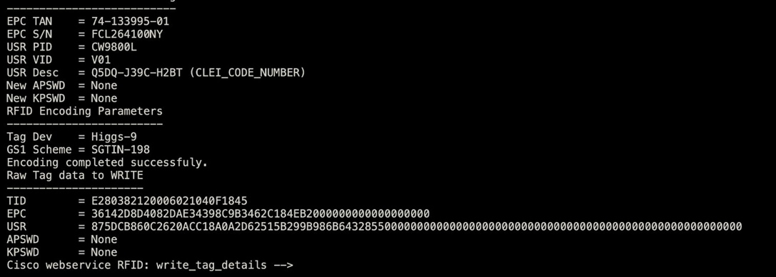
Table 11. Ordering information
| Type |
Part # |
Product Description |
| Controller |
CW9800L |
Cisco CW9800L Wireless Controller |
| Accessories, Spare |
CW9800L-RPS= |
Redundant Power Supply kit, which includes:
● Redundant Power Supply module
● 8-pin to 6-pin DC cable to connect RPS to CW9800L
● An additional power supply with power cord
|
|
|
PWR-RPS-DC1= |
Spare Redundant Power Supply module (no PSU, no cables) |
|
|
CW9800L-RFID-1R |
RFID Asset Tag |
|
|
CW-ACC-MEM-32G |
Additional 32GB Storage for Application Hosting. |
|
|
CW9800L-RMNT |
Rack mount tray for CW9800L |
|
|
CW9800L-RMNT-R |
Rear rack mount bracket for CW9800L-RMNT |
| Power Adapter |
C9800-AC-110W |
Single output 12 V DC, 110 W 120/240 V AC adapter, shipped by default |
Find more warranty information on Cisco.com at the Product Warranties page.
Cisco 1-year limited hardware warranty terms
The following are terms applicable to your hardware warranty. Your embedded software is subject to the Cisco General Terms and/or any Supplemental General Terms or specific software warranty terms for additional software products loaded on the device.
Duration of hardware warranty: One (1) year
Replacement, repair, or refund procedure for hardware: Cisco or its service center will use commercially reasonable efforts to ship a replacement part within ten (10) working days after receipt of the RMA request. Actual delivery times may vary depending on customer location.
Cisco reserves the right to refund the purchase price as its exclusive warranty remedy.
Flexible payment solutions to help you achieve your objectives
Cisco Capital makes it easier to get the right technology to achieve your objectives, enable business transformation and help you stay competitive. We can help you reduce the total cost of ownership, conserve capital, and accelerate growth. In more than 100 countries, our flexible payment solutions can help you acquire hardware, software, services and complementary third-party equipment in easy, predictable payments. Learn more.
Our experts recommend
Cisco Catalyst 9800 Series Wireless Controllers
CW9800L Wireless Controller At-A-Glance
Cisco Catalyst 9800 Series Wireless Controllers FAQ
Cisco Catalyst 9800 Series Wireless Controllers At-A-Glance