Cisco Catalyst 9800 Series: A Primer on Enterprise WLAN Roaming
Available Languages
Bias-Free Language
The documentation set for this product strives to use bias-free language. For the purposes of this documentation set, bias-free is defined as language that does not imply discrimination based on age, disability, gender, racial identity, ethnic identity, sexual orientation, socioeconomic status, and intersectionality. Exceptions may be present in the documentation due to language that is hardcoded in the user interfaces of the product software, language used based on RFP documentation, or language that is used by a referenced third-party product. Learn more about how Cisco is using Inclusive Language.
Note: The documentation set for this product strives to use bias-free language. For purposes of this documentation set, bias-free is defined as language that does not imply discrimination based on age, disability, gender, racial identity, ethnic identity, sexual orientation, socioeconomic status, and intersectionality. Exceptions may be present in the documentation due to language that is hardcoded in the user interfaces of the product software, language used based on RFP documentation, or language that is used by a referenced third-party product.
The Cisco® wireless solution is designed to provide 802.11 wireless networking solutions for enterprises and service providers. It simplifies the deployment and management of large-scale wireless LANs (WLANs) and enables a unique best-in-class security infrastructure. The operating system manages all data client, communications, and system administration functions, performs Radio Resource Management (RRM) functions, manages system wide mobility policies using the operating system security solution, and coordinates all security functions using the operating system security framework.
The Cisco wireless solution has evolved over the last 20 years, starting from the first-generation 802.11b (Wi-Fi 1) to 802.11ax (Wi-Fi 6) technology, and it continues to evolve with continuous, best-in-class innovation to offer the best Wi-Fi experience to customers.
With intent-based networking built on the Cisco Digital Network Architecture (Cisco DNA), Cisco enterprise wireless solutions go beyond the latest Wi-Fi 6 (802.11ax) standard and are ready for growing user expectations, Internet of Things (IoT) devices, and next generation cloud-driven applications.
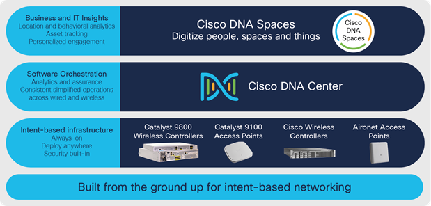
Cisco next-generation wireless stack
The core components of the Cisco wireless stack in the intent-based infrastructure are as follows:
Cisco Catalyst® 9800 Series Wireless Controllers: The Catalyst wireless controllers (WLCs) streamline the best of RF excellence with the benefits of open, programmable Cisco IOS® XE, meaning you no longer have two operating systems to manage. These modular, scalable, reliable, and highly secure controllers are flexible enough to deploy anywhere—including your choice of cloud.
The Cisco Catalyst 9800 software has been rewritten from scratch to leverage the benefits of Cisco IOS XE, and the configuration model has been made more modular and flexible. This means that although most AireOS features are retained, there might be changes in the way you configure certain functionalities.
Cisco Catalyst 9100 Access Points: Going beyond the Wi-Fi 6 standard, the Catalyst 9100 Access Points (APs) provide integrated security, resiliency, and operational flexibility, as well as increased network intelligence. These access points extend Cisco’s intent-based network and scale to the growing demands of the IoT while fully supporting the latest innovations and newest technologies, making them perfect for organizations of all sizes.
To get a complete overview and learn more about Cisco enterprise wireless products and solutions, please visit the following page: https://www.cisco.com/site/us/en/products/networking/wireless/index.html
This document serves as a technical guide and reference for one of the most important functionalities offered by the Cisco wireless infrastructure, namely seamless secure mobility, based on Cisco Catalyst 9800 Series Wireless Controllers running on the Cisco IOS XE operating system. It aims to explain the different roaming technologies with explanations and references to packet captures and provides a walk-through of configuring the Catalyst 9800 Series controller and also some best practices. This document also explains Inter-Release Controller Mobility (IRCM) between AireOS-based WLCs and Cisco IOS XE based WLCs.
Note: This document does not delve into the RF design and considerations needed for Wi-Fi client roaming.
Mobility, or roaming, supports a wireless LAN client’s ability to maintain its association seamlessly from one access point to another, securely and with as little latency as possible. This section explains how mobility works when controllers are included in a wireless network.
2.1 Campus deployment – APs in local mode
When a wireless client associates and authenticates to an access point, the access point’s controller places an entry for that client in its client database. This entry includes the client’s MAC and IP addresses, security context and associations, Quality of Service (QoS) contexts, the WLAN, and the associated access point. The controller uses this information to forward frames and manage traffic to and from the wireless client.
The figure below shows a wireless client that roams from one local mode access point to another local mode access point when both access points are joined to the same controller.
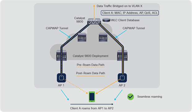
Catalyst 9800 intra-controller roaming
When the wireless client moves its association from one access point to another, the controller simply updates the client database with the newly associated access point. If necessary, a new security context and new associations are established as well.
The process becomes more complicated, however, when a client roams from an access point joined to one controller to an access point joined to a different controller. It also varies based on whether the controllers are operating on the same subnet.
The figure below shows inter-controller Layer 2 roaming, which occurs when the wireless LAN interfaces of the controllers are on the same IP subnet.
Note: The Catalyst 9800 Series has a new configuration model and introduces the concept of profiles and tags. In a Catalyst 9800 deployment, it is possible for a wireless controller to roam from one AP to another AP in the same controller, but mapped to a different policy. The new configuration model is explained in detail in a later section, and scenarios involving intra-controller and inter-policy tag roaming are explained as well.
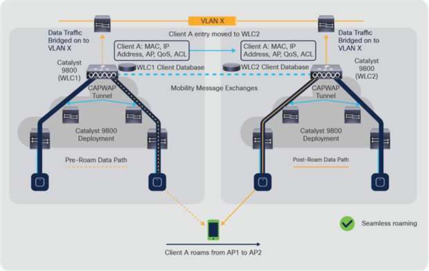
Catalyst 9800 inter-controller Layer 2 roaming
When the client associates to an access point joined to a new controller, the new controller exchanges mobility messages with the original controller, and the client database entry is moved to the new controller. A new security context and associations are established if necessary, and the client database entry is updated for the new access point. This process remains transparent to the user.
The figure below shows inter-controller Layer 3 roaming, which occurs when the wireless LAN interfaces of the controllers are on different IP subnets.
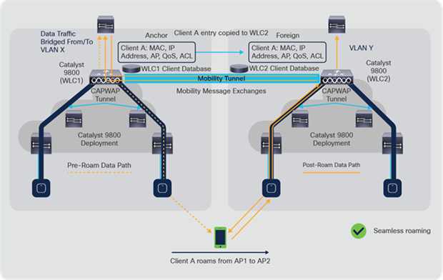
Catalyst 9800 inter-controller Layer 3 roaming
Layer 3 roaming is similar to Layer 2 roaming in that the controllers exchange mobility messages on the client roam. However, instead of moving the client database entry to the new controller, the original controller marks the client with an “Anchor” entry in its own client database. The database entry is copied to the new controller client database, where it is marked with a “Foreign” entry. The roam remains transparent to the wireless client, and the client maintains its original IP address.
2.2 Remote office deployment – APs in FlexConnect mode
Cisco FlexConnect® is a wireless solution for branch office and remote office deployments. It enables customers to configure and control access points in a branch or remote office from the corporate office through a WAN link without deploying a controller in each office. The FlexConnect access points have the flexibility to switch client data traffic centrally or locally and perform client authentication centrally or locally when their connection to the controller is lost.
For a client to roam seamlessly in a remote office deployment with access points in FlexConnect mode, a Flex site tag is required. A Flex site tag is a means of grouping the access points at a remote site, similar to a mobility domain in local mode, that facilitates seamless roaming of clients within the group of APs. Fast roaming is achieved by caching a derivative of the master key from a full Extensible Authentication Protocol (EAP) authentication so that a simple and secure key exchange can occur when a wireless client roams to a different access point. This feature avoids the need to perform a full RADIUS EAP authentication as the client roams from one access point to another. The FlexConnect access points need to obtain the CCKM/OKC/11r cache information for all the clients that might associate to them, so they can process the information quickly instead of sending it back to the controller. If, for example, you have a controller with 300 access points and 100 clients that might associate to them, sending the CCKM/OKC/11r cache for all 100 clients is not practical. If you create a Flex site tag comprising a limited number of access points (for example, if you create a group of four access points in a remote office), the clients roam only among those four access points, and the CCKM/OKC/11r cache is distributed among those four access points only when the clients associate to one of them.
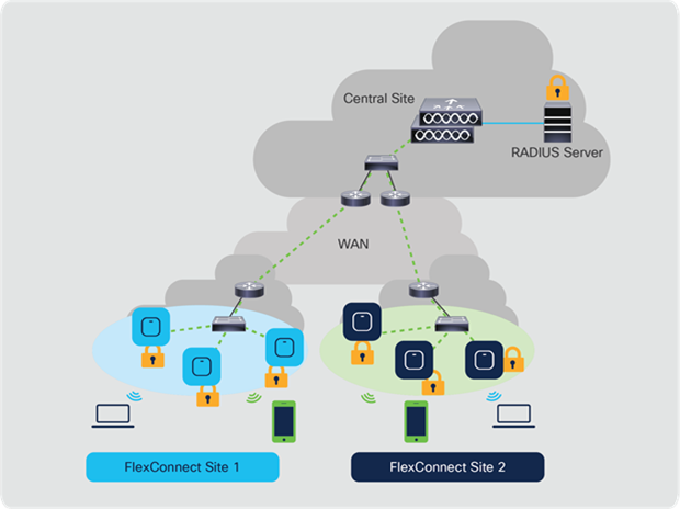
FlexConnect architecture
3. 802.11 roaming (Layer 2 roaming)
A wireless client roam occurs when the wireless device sees a better signal from a neighboring access point than from its own access point to which it’s been associated for a consistent period of time. The decision as to when exactly to roam is dictated by the client device and is mostly vendor specific. The wireless infrastructure, if set up properly, aids in the handoff process.
The handoff process consists of three phases:
1. Scanning: A wireless client periodically collects information about its environment through passive scanning (beacons) and active scanning (probes). This includes information about the WLAN, access points, and the Received Signal Strength Indication (RSSI) levels at which it hears the neighboring access points. When the RSSI values begin to drop below a certain threshold level, the wireless client device probes to find alternate access points to associate to and decides the next best access point to which it can roam. Most clients these days start to look for alternative access points if the RSSI drops below -70 to -75 dBm. (This is a vendor-specific implementation detail and could vary depending on the vendor). If the client sees the signal level consistently below its threshold, it initiates the next step in the roaming process, authentication.
2. Authentication: When the wireless client decides on the access point to which it wants to roam, it sends an authentication frame to the new access point and waits for the access point to respond with an authentication frame. Think of this open system authentication process as “connecting the cable” and “establishing the physical link” when compared to the wired world.
3. Reassociation: After the authentication phase, the wireless client sends a reassociation request frame to the new access point, expressing its interest in roaming within the extended service set with the information about the previous access point. The access point responds with a reassociation response to the wireless client, along with an Association ID (AID). The infrastructure now takes care of clearing the old mapping of the client to its previous access point.
If no higher-level Layer 2 security is configured on the WLAN, the handoff process is complete at this stage and the wireless client can start passing traffic.
Apart from higher-level security, WLANs are also mapped to access policies, such as VLAN, Access Control Lists (ACLs), and QoS. In a typical campus environment, the Service Set Identifier (SSID) broadcasted by all the access points in the campus will be same, but the access policies could differ within the campus, based on the location of the access point and the WLAN controller to which the access point is associated. When a wireless client roam happens within the extended service set and access policies remain the same after the roam, whether it be an inter-controller or intra-controller roam, it’s considered a Layer 2 (L2) roam. All that happens in an L2 roam is reassociation to a new access point with a better signal, with no change in Layer 3 parameters. When the client roams and access policies change in the roamed environment, and the infrastructure helps preserve the IP address and policies associated with the wireless client device in the roamed environment, it’s considered a Layer 3 (L3) roam. In any case, the role of the Cisco Unified Wireless Network infrastructure is to provide a seamless, fast, and secure roam for the best wireless experience for end users.
When the SSID is configured with L2 higher-level security on top of basic 802.11 open system authentication, more frames are required for the initial association and when roaming. The two most common security methods standardized and implemented for 802.11 WLANs are:
● WPA/WPA2-PSK (Wi-Fi Protected Access 2 – Preshared Key), also known as WPA2-Personal: Authentication of clients with a preshared key.
● WPA/WPA2-EAP, also known as WPA2-Enterprise: Authentication of clients with an 802.1X/EAP method in order to validate more secure credentials through the use of an authentication server, such as certificates, username and password, and tokens.
The 802.11 standard specifies the use of EAP and 802.1X for user authentication and dynamic key distribution. The call flow diagram of a high-level EAP framework is provided below for reference. Please note that there are different EAP methods (like EAP Transport Layer Security [EAP-TLS], Protected EAP [PEAP], EAP Flexible Authentication via Secure Tunneling [EAP-FAST], Lightweight EAP [LEAP], and so on), and the call flow during the certificate exchange and EAP authentication exchange varies slightly among these variations.
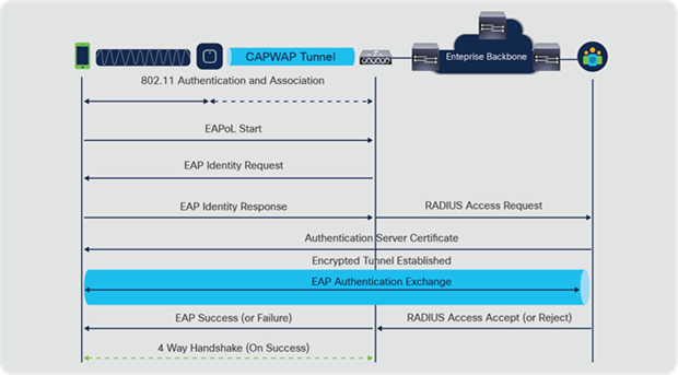
EAP/802.1X call flow
It is important to know that even though these two methods (PSK and EAP) authenticate/validate the clients in different ways, both use basically the same WPA/WPA2 rules for the key management process. Whether the security is WPA/WPA2-PSK or WPA/WPA2-EAP, the process known as the WPA/WPA2 4-way handshake begins the key negotiation between the WLC/AP and the client, with a Master Session Key (MSK) as the original key material once the client is validated with the specific authentication method used.
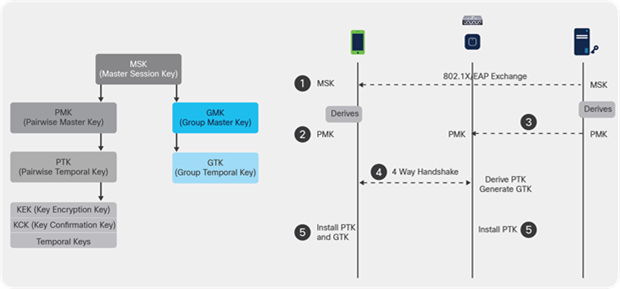
802.11 key management and distribution
Here is a summary of the process:
1. An MSK is derived from the EAP authentication phase when 802.1X/EAP security is used, or from the PSK when WPA/WPA2-PSK is used as the security method.
2. From this MSK, the client and WLC/AP derive the Pairwise Master Key (PMK), and the WLC/AP generates a Group Master Key (GMK).
3. Once these two master keys are ready, the client and the WLC/AP initiate the WPA/WPA2 4-way handshake (which is illustrated later in this document with some screen captures), with the master keys as the seeds for negotiation of the actual encryption keys.
4. Those final encryption keys are known as the Pairwise Transient Key (PTK) and the Group Transient Key (GTK). The PTK is derived from the PMK and is in order to encrypt unicast frames with the client. The GTK is derived from the GMK and is used to encrypt multicast/broadcast on this specific SSID/AP.
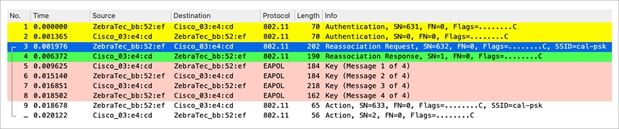
When WPA-PSK or WPA2-PSK is performed via Temporal Key Integrity Protocol (TKIP) or Advanced Encryption Standard (AES) for the encryption, the client must go through the process known as the WPA 4-way handshake for both the initial association and also when roaming. As previously explained, this is basically the key management process used in order for WPA/WPA2 to derive the encryption keys. However, when PSK is performed, it is also used to verify that the client has a valid preshared key to join the WLAN.
This capture shows the initial association process when WPA or WPA2 with PSK is performed.
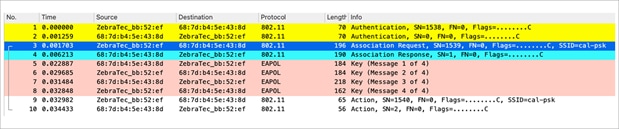
Packet capture – WPA/WPA2 PSK initial association
As shown, after the 802.11 open system authentication and association process, there are four EAP over LAN (EAPOL) frames from the WPA 4-way handshake, which are initiated by the AP with message-1 (the PMK is sent in this frame) and finished by the client with message-4. After a successful handshake, the client begins to pass data frames (such as Dynamic Host Configuration Protocol [DHCP]), which in this case are encrypted with the keys derived from the 4-way handshake (this is why you cannot see the actual content and type of traffic from the wireless captures).
Note: EAPOL frames are used to transport all of the key management frames and 802.1X/EAP authentication frames over the air between the AP and the client; they are transmitted as wireless data frames.
When roaming, the client basically follows the same frame exchange, in which the WPA 4-way handshake is required in order to derive new encryption keys with the new access point. This is done for security reasons established by the standard, and is due to the fact that the new AP does not know the original keys.
The only difference is that there are reassociation frames instead of association frames, as shown in this capture:
Packet capture – WPA/WPA2 PSK reassociation
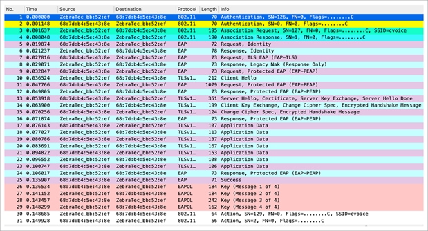
When an 802.1X/EAP method is used to authenticate the clients on a secure SSID, even more frames are required before the client begins to pass traffic. These extra frames are used to authenticate the client credentials, and depending on the EAP method, there might be between 4 and 20 of these frames. These come after the association or reassociation but before the WPA/WPA2 4-way handshake, because the authentication phase derives the MSK used as the seed for the final encryption key generation in the key management process (4-way handshake).
The wireless capture below shows an example of the frames exchanged over the air between the access point and the wireless client upon initial association when WPA with PEAPv0 and EAP Microsoft Challenge Handshake Authentication Protocol (EAP-MSCHAPv2) is performed.
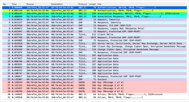
Packet capture – WPA/WPA2 802.1X initial association
Sometimes this exchange shows more or fewer frames, depending on multiple factors, such as the EAP method, retransmissions due to problems, client behavior, or whether the client already exchanged the certificate with the server. Whenever the SSID is configured for an 802.1X/EAP method, there are more frames (for the authentication), and hence more time is required before the client begins to send data frames.
When the wireless client performs a regular roam here (the normal behavior, without implementation of a fast secure roaming method), the client must go through the exact same process and perform a full authentication against the authentication server, as shown in the captures. The only difference is that the client uses a reassociation request to inform the new AP that it is actually roaming from another AP, but the client still has to go through full validation and new key generation.
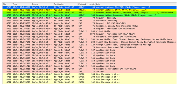
Packet capture – WPA/WPA2 802.1X reassociation
As shown, even when there are fewer frames than in the initial authentication (which is caused by multiple factors, as mentioned before), when the client roams to a new AP, the EAP authentication and the WPA key management processes must still be completed in order to continue to pass data frames (even if traffic was actively sent before roaming). Therefore, if the client has an active application that is sensitive to delays (such as voice traffic applications or applications that are sensitive to timeouts), the user can perceive problems when roaming, such as audio gaps or application disconnects. The extent of these problems depends on how long it takes for the client to continue to send and receive data frames. Factors in the length of the delay include the RF environment, the number of clients, the round-trip time between the WLC and APs and with the authentication server, and other reasons such as neighbor-list exhaustion on the client that makes the client do a full channel scan to find the next available APs.
This is how the 802.1X/EAP and WPA/WPA2 security framework works. To prevent delays from a regular roaming event from impacting applications and services, multiple fast secure roaming methods have been developed and implemented by the Wi-Fi industry to accelerate the roaming process when security is used on the WLAN/SSID. The clients face some latency when they continue to pass traffic while roaming between APs due to deployment of high-level security on the WLAN. This is related to the EAP authentication and key-management frame exchanges required by the security setup, as previously explained.
It is important to understand that fast secure roaming is the term used by Cisco to refer to the implementation of a method/scheme that accelerates the roaming process when security is configured on the WLAN. The different fast secure roaming methods/schemes that are available for WLANs and supported by the Cisco Catalyst wireless infrastructure (Catalyst 9800 Series controllers, Catalyst 9100 access points, and Cisco Aironet® Wave 1 and Wave 2 access points) are explained in the next section.
As seen in the previous section, there is latency involved while roaming with higher-level security due to the EAP authentication and key-management frame exchanges. To prevent delays in applications or services caused by a regular roaming event, multiple fast secure roaming methods have been developed and implemented by the Wi-Fi industry.
Fast secure roaming helps avoid full authentication by skipping the EAP exchange when the client roams between APs. There is still some latency involved, due to key-management frame exchanges, but it’s minimal.
Fast secure roaming is a term used by Cisco to reference the method that accelerates the roaming process of the clients when Layer 2 security is configured on the WLAN. The different implementations are listed in the table below, along with whether they are supported in the Catalyst 9800 Series local and FlexConnect deployment modes.
Table 1. Supported fast secure roaming methods in the Catalyst 9800 Series controllers
| Method |
Local mode |
FlexConnect (connected mode) (central authentication) |
FlexConnect (connected mode) (local authentication) |
FlexConnect (standalone) |
| SKC |
Not supported |
Not supported |
Not supported |
Not supported |
| OKC |
Supported |
Supported |
Supported |
Supported* |
| CCKM |
Supported |
Supported |
Supported |
Not supported |
| FT-802.11r/ Adaptive 11r |
Supported |
Supported |
Supported |
Supported* |
| FT-8011.r/ Adaptive 11r |
Supported |
Supported |
Not supported |
Not supported |
A detailed description of each method supported in the Catalyst 9800 Series is given below, along with packet captures and configuration knobs.
Note: A couple of methods, namely Sticky Key Caching (SKC) and preauthentication, are not supported by the Cisco WLAN infrastructure. However, for technical completeness, we give explanations of these methods as well.
3.2.1 Fast secure roaming with PMKID caching (sticky key caching)
Pairwise Master Key ID (PMKID) caching, or Sticky Key Caching (SKC), is the first fast secure roaming method suggested by the IEEE 802.11 standard within the 802.11i security amendment, where the main purpose is to standardize a high level of security for WLANs. This fast secure roaming technique was added as an optional method for WPA2 devices in order to improve roaming when this security is implemented.
With this method, the WLC (in local mode), AP (in FlexConnect mode), and wireless client cache the PMKs of the secure associations (built through a full 802.1X/EAP authentication) already established. Therefore, if the wireless client roams to a new AP where it has never associated, the client must perform a full EAP authentication again. The wireless client station includes the PMKID in the reassociation request frame when it reassociates. If the controller or AP has the PMK cached, the EAP exchange will be skipped and only the 4-way handshake key management occurs.
This method has a big limitation on its implementation: Wireless clients can perform fast secure roaming only when roaming back to an AP where they had previously authenticated and connected.
With this method, the initial association to any AP is just like a regular first-time authentication to the WLAN, where the entire 802.1X/EAP authentication against the authentication server and the 4-way handshake for key generation must happen before the client is able to send data frames.
Note: This is not a widely deployed fast secure roaming method. It is not supported in the Catalyst 9800 Series controllers and has been deprecated.
3.2.2 Fast secure roaming with Opportunistic Key Caching (OKC)
Opportunistic Key Caching (OKC), also known as Proactive Key Caching (PKC), is basically an enhancement of the WPA2 PMKID caching method described previously. This fast secure roaming method is not defined in the 802.11 standard.
OKC is used at both the client device and the WLC or AP, depending on the deployment. This technique allows the wireless client and the WLAN infrastructure to cache only one PMK for the lifetime of the client association with this WLAN (derived from the MSK after the initial 802.1X/EAP authentication with the authentication server), even when roaming between multiple APs, as they all share the original PMK that is used as the seed on all WPA2 4-way handshakes. The 4-way handshake is still required, just as it is in SKC, in order to generate new encryption keys every time the client reassociates with the APs.
For the APs to share this one original PMK from the client session, they must all be under some sort of administrative control, with a centralized device that caches and distributes the original PMK for all of the APs. The Catalyst 9800 Series WLC performs this job for all the APs joined and under its control and distributes the PMK to other WLCs in the mobility group.
The Wireshark screen shot for the initial association of the client is shown below. The initial association requires the entire 802.1X/EAP authentication with the authentication server and the 4-way handshake for key generation.
Packet capture – WPA/WPA2 802.1X initial association (OKC)
In this method, the wireless client and the WLC (for local mode) and APs in a FlexConnect group (for Flex mode) cache the one original PMK of the secure association that is initially established. Basically, every time the wireless client connects to a specific AP, a PMKID is hashed based on:
● The client’s MAC address
● The AP’s MAC address (BSSID of the WLAN)
● The PMK derived with that AP
Therefore, since OKC caches the same original PMK for all of the APs and the specific client, when this client (re)associates to another AP, the only value that changes in order to hash the new PMKID is the new AP MAC address.
When the client initiates roaming to a new AP and sends the reassociation request frame, it adds the PMKID on the WPA2 Robust Security Network information element (RSN IE) if it wants to inform the AP that a cached PMK is used for fast secure roaming (as it already knows the MAC address of the target AP to which it wants to roam). When the AP receives this request from the client, it also hashes the PMKID with the values it already has (the cached PMK, the client MAC address, and its own AP MAC address), and responds with the successful reassociation response confirming that the PMKIDs matched. The cached PMK can be used as the seed that starts a WPA2 4-way handshake in order to derive the new encryption keys.
The Wireshark capture during the roam involving OKC is presented below. The 802.1X/EAP exchange is completely skipped, and only the 4-way handshake occurs to derive the new encryption keys.
If the wireless client presents the PMKID but the infrastructure does not support OKC for some reason, the WLC or AP will ignore the PMKID presented by the client and will initiate a full authentication.
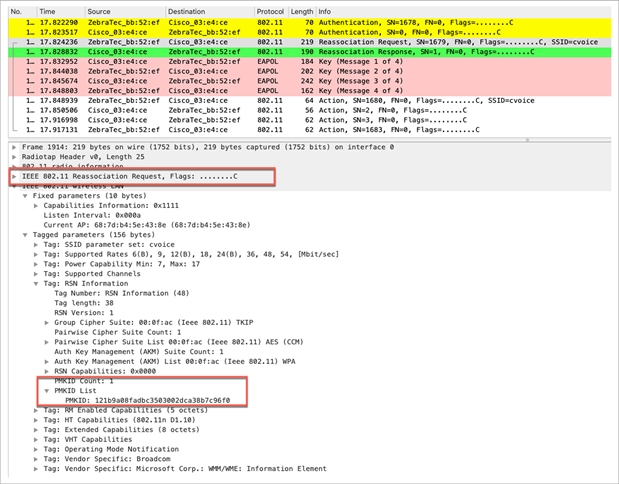
Packet capture – OKC client roam
Configuration steps:
● OKC is enabled by default in the Catalyst 9800 Series controller. Enabling FT Only or CCKM in the WLAN security settings disables OKC.
● OKC can be disabled globally for the Flex mode deployments. This will disable OKC and make it a full authentication roam for the clients in the FlexConnect group.
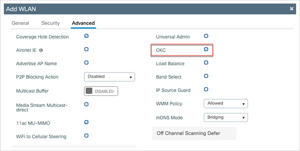
WLAN configuration
Note: Disabling OKC at the WLAN does not disable the default behavior of disabling OKC for local mode.
Roam history
OKC fast secure roam can be confirmed in the client details from the Mobility History tab.
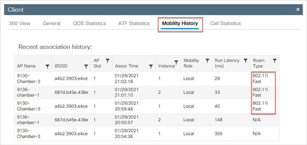
Client roam history with OKC
802.11i Fast as the Roam Type in the Mobility History indicates the OKC fast secure roam method for the client.
FlexConnect with OKC
● Central authentication is supported. This includes local and central data switching. If the AP is part of the same FlexConnect group, fast secure roaming is by the AP.
● Flex local authentication is supported. In connected mode, the cache will be distributed from the AP to the controller and then to the rest of the APs in the FlexConnect croup.
● Standalone mode is supported. If the cache is already present on the AP (due to previous distribution), fast secure roam will work until the session times out. New authentication in standalone mode does not support fast secure roaming.
Pros with OKC
● Requires only one initial 802.1X/EAP authentication.
● Wireless client performs fast secure roam to a new AP on the WLAN even if it was never associated to that AP before.
● Scales well.
● The wireless client and the WLAN infrastructure do not need to remember multiple PMKIDs, but simply cache the one original PMK from the initial authentication to the WLAN.
Cons with OKC
● Some clients do not support it.
● The techniques that are applied in this method are not suggested or described in the 802.11 standard, so support varies widely from one device to another. Nevertheless, this is one of the more popular methods in non-Fast Transition (FT) environments.
Note about the term “proactive key caching”
The terms Proactive Key Caching (PKC) and Opportunistic Key Caching (OKC) have been used interchangeably to describe the method explained here. However, PKC is just a term that was used by Airspace in 2001 for an old key caching method, which was then used by the 802.11i standard as the basis for “preauthentication” (another fast secure roaming method briefly explained below). PKC is not preauthentication or OKC, but when you hear or read about PKC, the reference is basically to OKC, and not to preauthentication.
3.2.4 Fast secure roaming with CCKM
Cisco Centralized Key Management (CCKM) is the first fast secure roaming method developed and implemented on enterprise WLANs, created by Cisco to mitigate the delays explained earlier when 802.1X/EAP security is used on the WLAN. As this is a Cisco proprietary protocol, it is supported only by Cisco WLAN infrastructure devices and wireless clients (from multiple vendors) that are Cisco Compatible Extension (CCX) compatible with CCKM.
CCKM can be implemented with all of the different encryption methods available for WLANs (TKIP and AES). It is also supported with most of the 802.1X/EAP authentication methods used for WLANs, depending on the CCX version supported by the devices.
Support for CCKM is indicated in the Authentication and Key Management (AKM) suite of RSN IE in beacon, probe response, and association request frames.
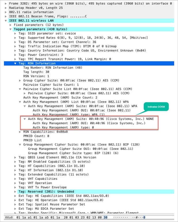
Packet capture – RSN information with CCKM
The wireless capture below provides an example of the frames exchanged upon initial association when you perform CCKM with TKIP as the encryption and PEAPv0/EAP-MSCHAPv2 as the 802.1X/EAP method. This is basically the same exchange as if WPA/TKIP with PEAPv0/EAP-MSCHAPv2 were performed, but this time CCKM between the client and the infrastructure is negotiated so that they use different key hierarchy and cache methods to perform fast secure roaming when the client must roam.
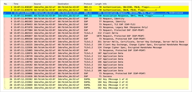
Packet capture – CCKM initial association
With CCKM, the initial association to the WLAN is similar to that in the regular WPA/WPA2, where an MSK (also known here as the Network Session Key [NSK]) is mutually derived with the client and the RADIUS server. This master key is sent from the server to the WLC after a successful authentication and is cached as the basis for deriving all subsequent keys for the lifetime of the client association with this WLAN. From here, the WLC and the client derive the seed information that is used for fast secure roaming based on CCKM, going through a 4-way handshake similar to that of WPA/WPA2 to derive the unicast (PTK) and multicast/broadcast (GTK) encryption keys with the first AP.
The big difference is noticed when roaming. In this case, the CCKM client sends a single reassociation request frame to the AP/WLC (including a manufacturer installed certificate [MIC] and a sequentially incrementing random number) and provides enough information (including the new AP MAC address BSSID) to derive the new PTK. With this reassociation request, the WLC and new AP also have enough information to derive the new PTK, so they simply respond with a reassociation response. The client can now continue to pass traffic, as shown in this capture:
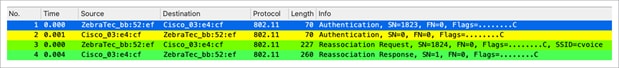
Packet capture – reassociation with CCKM
As shown, fast secure roaming is performed while avoiding the EAP authentication frames and even more 4-way handshakes, because the new encryption keys are still derived but are based on the CCKM negotiation scheme. This is completed with the roaming reassociation frames and the information previously cached by the client and the WLC.
Configuration steps:
To have a CCKM WLAN, disable Fast Transition and select CCKM for Auth Key Mgmt on the Security -> Layer 2 tab.
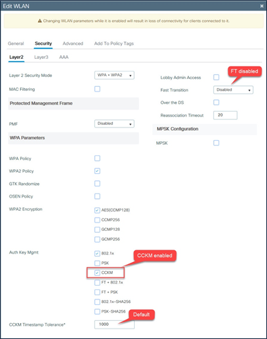
WLAN configuration – CCKM
Client details and roam history
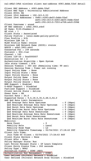
Client details and roam history – CCKM
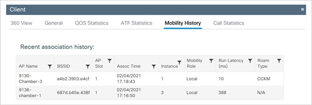
Client roam history – CCKM
FlexConnect with CCKM
● Central authentication is supported. This includes local and central data switching. The APs must be part of the same FlexConnect group.
● Flex local authentication is supported. In connected mode, the cache will be distributed from the AP to the controller and then to the rest of the APs in the FlexConnect group.
● New authentications in standalone mode is not supported. If the cache is already present on the AP (due to previous distribution), fast secure roaming with CCKM will work.
Pros with CCKM
● CCKM is the fastest fast secure roaming method, mostly deployed on enterprise WLANs. Clients do not need to go over a key management handshake in order to derive new keys when a move between APs takes place, and are never again required to perform a full 802.1X/EAP authentication with new APs during the client lifetime on this WLAN.
● CCKM supports all of the encryption methods available within the 802.11 standard (Wired Equivalent Privacy [WEP], TKIP, and AES), in addition to some legacy Cisco proprietary methods still used on legacy clients.
Cons with CCKM
● CCKM is a Cisco proprietary method, which limits the implementation and support to Cisco WLAN infrastructure and CCX wireless clients.
● CCX Version 5 is not widely adopted, so CCKM with WPA2/AES is not supported by many CCX wireless clients (mainly because most of them already support CCKM with WPA/TKIP, which is still very secure).
3.2.3 Fast secure roaming with 802.11r
The 802.11r Fast Transition (FT) roaming, officially named Fast BSS Transition, is an amendment to the 802.11 IEEE standards. “BSS transition” refers to the process of disconnecting from one access point and connecting to another without losing connectivity. In Fast BSS Transition, the initial handshake with the new access point occurs before the client roams to the target access point, thus helping to reduce the time it takes to transition to the new access point and making it "fast.”
Fast Transition key hierarchy
The FT key hierarchy introduces new concepts and multiple layers of PMKs that are cached in the different devices in the WLAN infrastructure. The IEEE 802.11r amendment specifies three layers of key hierarchy.
The Master Session Key (MSK) is derived from the client supplicant and the authentication server from the 802.1X/EAP initial authentication. (The MSK is transferred from the authentication server to the authenticator after the authentication is successful.) When PSK is used for authentication, the PSK is used as the MSK. The MSK, as in other methods, is used as the seed for the FT key hierarchy.
1. PMK-R0: Pairwise master key PMK-R0 is the first-level PMK and is derived from the MSK. The key holders for this PMK are the WLC and the client.
2. PMK-R1: Pairwise master key PMK-R1 is the second-level PMK and is derived from the PMK-R0. The key holders of PMK-R1 are the APs managed by the WLC and the client.
3. PTK: Pairwise Transient Key (PTK) is the third and final level key in the hierarchy. PTK is derived from PMK-R1 and is used to encrypt the data frames. The key holders of PTK are the APs and the client.
Fast Transition terminology
Fast BSS Transition: A wireless client roam from one AP (BSS) to another AP (BSS) within the same WLAN.
FT mobility domain: The set of APs (BSSs) within the WLAN that supports Fast BSS Transition, identified by the mobility domain identifier. The mobility domain identifier is broadcasted by the AP in beacons and probe response frames.
Fast Transition initial client association
The first association to any AP is a regular first-time authentication to the WLAN, in which the entire 802.1X/EAP authentication against the authentication server and the 4-way handshake for key generation must occur before data frames are sent, as shown in the following screen capture.
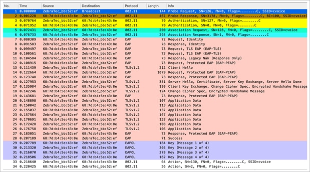
Packet capture – FT/802.11r initial association
The packet capture resembles a normal EAP authentication – that is, open authentication, association, EAP exchange, 4-way key handshake.
The differences are in the inclusion of additional information elements in the beacon, probe response, association request, and association response frames, which are highlighted below.
Beacon and probe response frames, contain a Mobility Domain Information Element (MDIE), which indicates the existence of mobility domain and FT support. The RSN information element also has an additional AKM suite (FT over IEEE 802.1X).
The association request frame from the wireless client includes the MDIE and the FT over IEEE 802.1X AKM suite in the RSN IE. The wireless client indicates its ability to do FT by including the MDIE and the support of security in the RSN IE in the association request frame.

Packet capture – FT/802.11r beacon
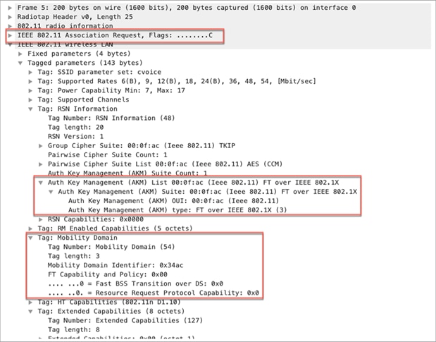
Packet capture – FT/802.11r association request
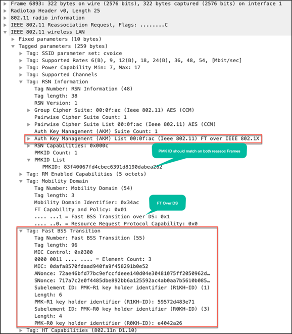
The WLC/AP responds to the association request in the association response frame by including an additional information element called the Fast BSS Transition Information Element (FTIE), in addition to the MDIE. The FTIE includes information such as MIC, ANonce, SNonce, PMK-R0 Key Holder Identifier (R0KH-ID), and PMK-R1 key holder identifier (R1KH-ID), which are needed to perform the FT authentication sequence during an FT BSS transition.
The next step in the process is an 802.1X/EAP packet exchange to arrive at the MSK, which is used as the seed for the FT key hierarchy. After a successful authentication, the WLC/AP and the wireless client do an FT 4-way key handshake. The FT 4-way handshake resembles a regular 4-way key handshake; however, the contents are different.
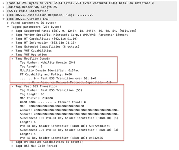
Packet capture – FT/802.11r association response
Methods of client roaming in FT
The FT key hierarchy is designed to allow clients to make Fast BSS Transitions between APs without requiring reauthentication at every AP. The WLAN configuration contains a new AKM type called FT.
For a client to move from the current AP to a target AP using FT protocols, the message exchanges are performed using one of the following two methods:
● Over the air: The client communicates directly with the target AP using IEEE 802.11 authentication with the FT authentication algorithm.
● Over the Distribution System (DS): The client communicates with the target AP through the current AP. The communication between the client and the target AP is carried in FT action frames between the client and the current AP and is then sent through the controller.
FT over the air
With Fast BSS Transition over the air, there are just four frame exchanges between the wireless client and the target AP over the air. The picture and packet capture below illustrate the four frame exchanges.
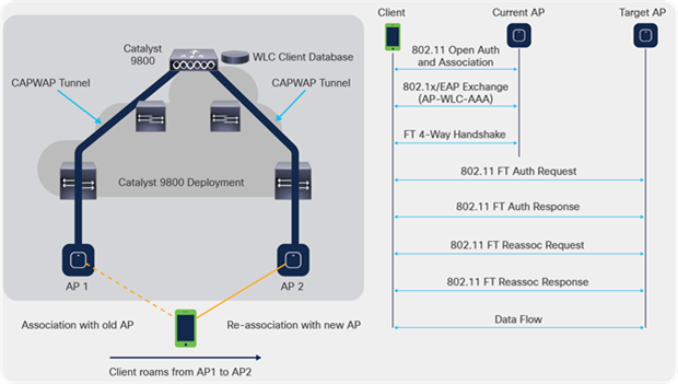
FT over-the-air call flow
FT not only avoids the 802.1X/EAP exchanges, but it’s more efficient, as it combines the initial 802.11 open system authentication and reassociation frames to exchange the FT information and derive new dynamic encryption keys in place of the explicit 4-way key handshake in other methods.

Packet capture – FT over the air
The next capture shows the frames exchanged when a Fast BSS Transition over the air with 802.1X/EAP security is performed. The open system authentication frame from the client to the AP is selected in order to see the FT protocol information elements that are required to begin the FT key negotiation. This is used to derive the new PTK with the new AP (based on the PMK-R1). The field that shows the authentication algorithm is highlighted to show that this client does not perform a simple open system authentication, but a Fast BSS Transition.
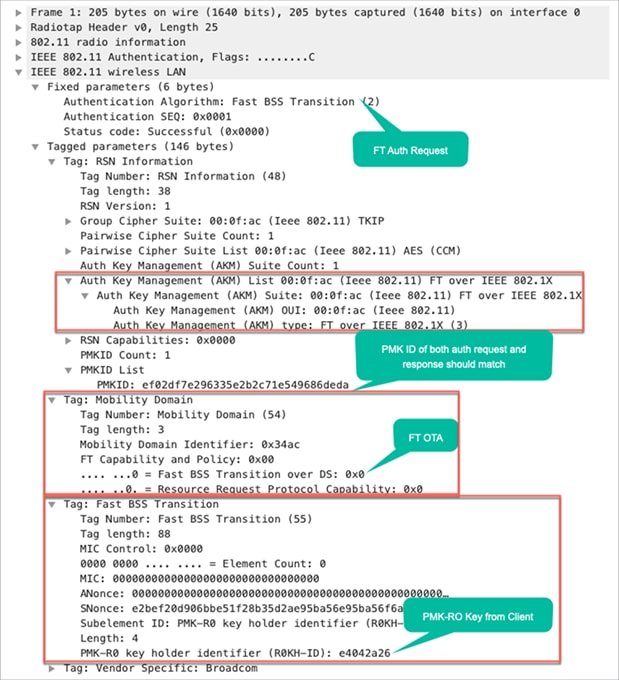
Packet capture – FT over-the-air authentication request
As shown in the capture, once the Fast BSS Transition is negotiated upon initial association to the WLAN, the four frames that are used and required for roaming (open system authentication from the client, open system authentication from the AP, reassociation request, and reassociation response) are basically used as an FT 4-way handshake to derive the new PTK (unicast encryption key) and GTK (multicast/broadcast encryption key).
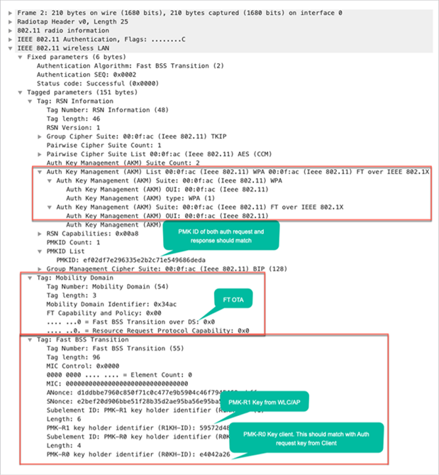
Packet capture – FT over-the-air authentication response
This substitutes for the 4-way handshake that normally occurs after these frames are exchanged, and the FT content and key negotiation on these frames is basically the same whether you use 802.1X/EAP or PSK as the security method. As shown in the capture, the AKM field is the main difference, which confirms whether the client performs FT with PSK or 802.1X. Therefore, it is important to note that these four frames normally do not have this type of security information for key negotiation. They have it only when client FT roams occur if 802.11r is implemented and negotiated between the client and the WLAN infrastructure upon initial association.
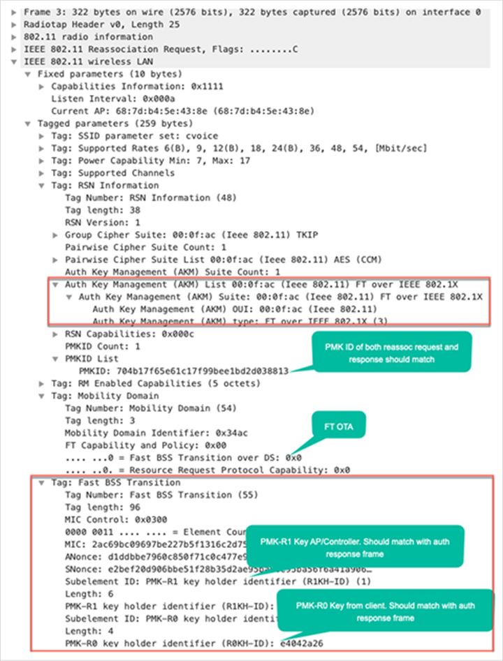
Packet capture – FT over-the-air reassociation request
Packet capture – FT over-the-air reassociation response
FT over the DS
802.11r allows another implementation of Fast BSS Transition, in which FT roaming is initiated by the client with the new AP to which the client roams over the DS (distribution system), and not over the air. In this case, FT action frames are used to initiate the key negotiation instead of the open system authentication frames.
Basically, once the client decides to roam to a better AP, the client sends an FT action request frame to the original AP where it is currently connected. The client indicates the BSSID (MAC address) of the target AP where it wants to roam. The original AP forwards this FT action request frame to the target AP over the distribution system (wired infrastructure), and the target AP responds to the client with an FT action response frame (also over the DS) to the original AP, so it can finally send it over the air to the client. Once this FT action frame exchange is successful, the client sends the reassociation request to the target AP (this time over the air), and receives a reassociation response from the new AP in order to confirm the roaming and final key derivation.
The picture and packet capture below illustrate this process.
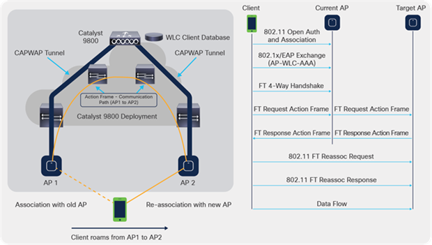
FT over-the-DS call flow
This method is also valid for both security methods, 802.1X/EAP and PSK. Not all wireless clients support FT over the DS. Hence, it is a configuration option in the Cisco WLC. (Over the air is enabled by default.)

Packet capture – FT over the DS
Details of the packet captures from the four frames are provided below for reference.
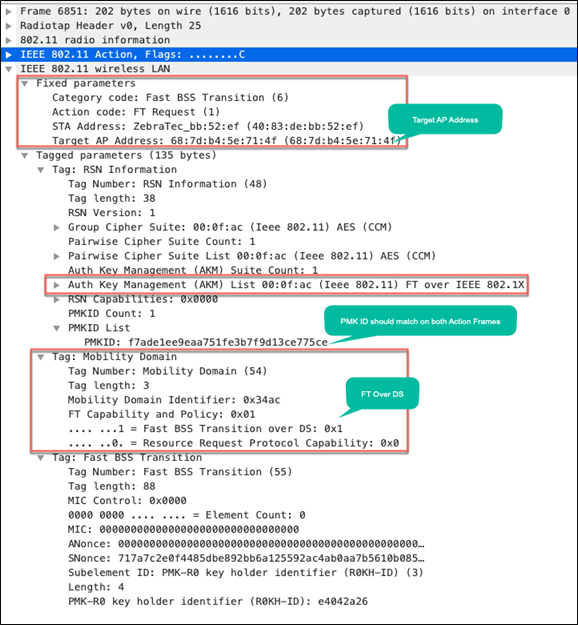
Packet capture – FT over the DS: Action frame from client
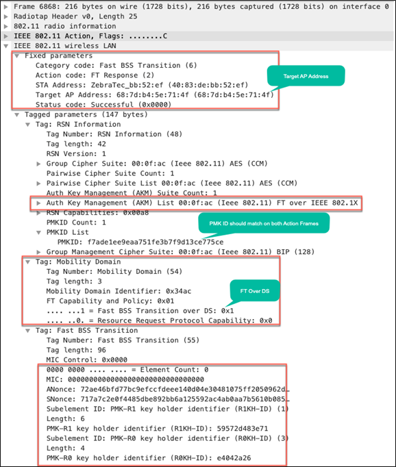
Packet capture – FT over the DS: Action frame from AP
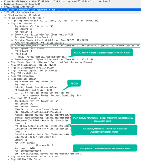
The reassociation request and response frames are very similar to the over-the-air exchange, except that mobility capability in the MDIE indicates Fast BSS Transition over the DS.
Packet capture – FT over the DS: Reassociation request from client
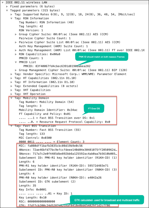
Packet capture – FT over the DS: Reassociation response from AP
Configuration steps:
● By default, when creating a WLAN with 802.1X, Adaptive Enabled Fast Transition is selected for Layer 2 security, with 802.1X as the Auth Key Mgmt option.
● Adaptive Enabled Fast Transition is the preferred configuration, as clients with no FT support can then join the WLAN also.
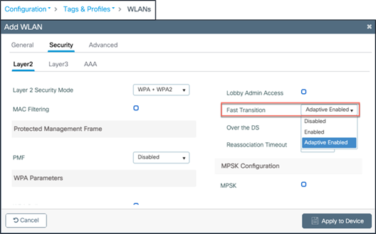
WLAN configuration with FT
● If an exclusive FT-only WLAN is needed, change Adaptive Enabled to Enabled, with FT+ 802.1X as the Auth Key Mgmt option.
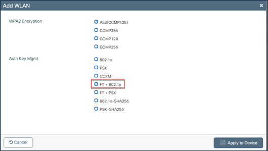
WLAN configuration – FT AKM
● The above conditions apply for a PSK WLAN as well.
● Over the air is the default roaming method and is enabled by default. If over-the-DS roaming is preferred, it has to be selected.
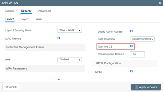
WLAN configuration – FT over the DS
Client roam history
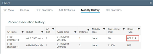
Client roam history – FT/802.11r
Adaptive 802.11r
Some legacy clients were not able to associate with a WLAN/SSID that has 802.11r enabled, even for "mixed mode" (one of the earlier supported modes, which had the expectation that both FT and non-FT clients could coexist without the need to create separate SSIDs for FT and non-FT). Many legacy wireless clients were not able to parse the additional AKM suites in the RSN IE. Due to this, the clients were unable to associate with the 802.11r enabled mixed-mode WLANs. This forced users to create separate WLANs for FT and non-FT clients.
In order to overcome this, the Cisco WLAN infrastructure introduced the adaptive 802.11r feature. When FT mode is set to adaptive at the WLAN level, the RSN IE does not have any FT methods but advertises the 802.11r mobility domain ID on an 802.11i-enabled WLAN on the beacon and probe response frames. Apple iOS clients (greater than iOS 10) and Samsung S10 devices and above identify the presence of an MDIE on an 80211i/WPA2 WLAN and do a proprietary handshake to establish 802.11r association. Once the client completes successful 802.11r association, it will be able to do FT roaming as in a normal 802.11r-enabled WLAN. With this mode, the RSN IE does not have any FT methods.
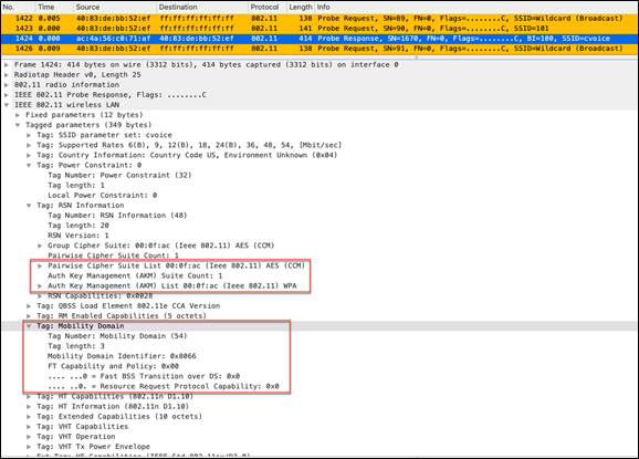
Adaptive 802.11r RSN and mobility domain IEs
FlexConnect with 802.11r
● FlexConnect with central authentication or local authentication in connected mode is supported.
● Roaming in standalone mode will work until the next session timeout.
● Over the DS is not supported with local authentication and standalone mode.
Pros with 802.11r
● This method is the first that uses a key hierarchy clearly defined by the IEEE on the 802.11 standard as an amendment (802.11r), so the implementation of these FT techniques are more compatible between vendors and without different interpretations. In short, it is standards based.
● This is the first fast secure roaming method that allows faster roaming, even with PSK security, and avoids the 4-way handshake that is required when roaming between APs with WPA/WPA2 PSK. The main purpose of the fast secure roaming methods is to avoid the 802.1X/EAP handshake when this security method is implemented; however, for PSK security the roaming event is accelerated even more with 802.11r by avoiding the 4-way handshake.
● The wireless client performs fast secure roaming to a new AP on the same WLAN/SSID, even if it never associated with that AP, and without the need to save multiple PMKIDs. In short, it is the most efficient standards-based, fast secure roaming method available today.
● 802.11r allows multiple roaming techniques (over the air and over the DS).
Cons with 802.11r
● Not all wireless client devices support Fast BSS Transition, and in most cases, they do not support all of the techniques available in 802.11r.
3.2.5 Fast secure roaming with preauthentication
This method is also suggested by the IEEE 802.11 standard within the 802.11i security amendment, so it also works with WPA2, but this fast secure roaming method is NOT supported by Cisco WLAN infrastructure, as not many clients available today support this method.
With preauthentication, the wireless clients can authenticate with multiple APs at a time while associated with the current AP. When this occurs, the client sends the EAP authentication frames to the current AP where it is connected, but it is destined to the other APs where the client wants to perform preauthentication (neighbor APs that are possible candidates for roaming). The current AP sends these frames to the target APs over the distribution system. The new AP performs full authentication against the RADIUS server for this client, so an entire new EAP authentication handshake is completed, and this new AP acts as the authenticator.
The idea is to perform authentication and derive a PMK with the neighbor APs before the client actually roams to them, so when it is time to roam, the client is already authenticated and a PMK is already cached for this new AP-to-client secure association, and they need only to perform the 4-way handshake and experience a fast roam after the client sends its initial reassociation request.
● The Catalyst 9800 Series supports most popular fast secure roaming methods in use today. The fast secure roaming methods supported in the Catalyst 9800 for different deployment models are provided in Table 1.
● It’s always the client that decides to roam – and when and where to roam. The roaming algorithm is vendor specific and the roaming behavior may not be the same among different vendors.
● All of the methods have some advantages and disadvantages.
● For fast secure roaming to work, the client should support the fast secure roaming method. Depending on the client type, it’s advised to enable the particular fast secure roaming method in your WLAN infrastructure. For example, if the deployment has many Cisco wireless IP phones, have a WLAN with CCKM enabled, and if the deployment has a mix of Apple iOS phones, Samsung S10 phones or above, and Windows or Mac laptops, have a WLAN with the adaptive 11r feature turned on.
● In FlexConnect deployments, fast secure roaming can happen only within the Flex site tag.
● Roaming times vary for different fast secure methods. The table below captures the typical time involved in a fast secure roam and typical client types that support a particular fast secure roaming method. The roaming time is also greatly dependent on the RF environment and the client types used.
Table 2. Fast secure roam time and client types
| Fast secure method |
Typical roam time |
Client types |
| Full authentication roam |
120 ms – a couple of seconds |
All client types |
| OKC |
8 ms to 100 ms |
Windows, Zebra clients |
| CCKM |
4 ms to 50 ms |
Cisco IP phones 7925/7926/8821/Zebra clients |
| 11r (over the air and over the DS) |
4 ms to 50 ms |
Windows, iPhones, iPads, Samsung S10 or above |
| Adaptive 11r |
4 ms to 50 ms |
iPhones, iPads, Samsung S10 or above |
Note: The low range in the roam time is measured in a lab in a perfect RF environment.
4. Catalyst 9800 configuration model
The Cisco Catalyst 9800 software has been rewritten from scratch to leverage the benefits of Cisco IOS XE, and the configuration model has been made more modular and flexible. This means that although most AireOS features are retained, there might be changes in the way you configure certain functionalities, and it’s important to understand the new configuration model.
The Catalyst 9800 Series controller configuration data model is based on design principles of reusability, simplified provisioning, enhanced flexibility, and modularization to help manage networks as they scale and simplify the management of dynamically changing business and IT requirements.
This model enables the client and AP devices to derive their configurations from profiles that are contained within tags. An AP can be mapped to the tags either statically or as part of the rule engine that runs on the controller and comes into effect during the AP join process. Configuration objects are modularized as objects, which helps in the reusability of the configuration. In addition, a flat tag-based configuration model eliminates the complexities associated with inheritance and container-based grouping, leading to a simpler and more flexible configuration that can ease change management.
4.1 Elements of the configuration model – profiles and tags
Profiles define a set of features, properties of the AP or associated clients. Profiles are reusable entities. Tags allow you to assign the profiles (or sets of features) to APs.
There are five types of profiles:
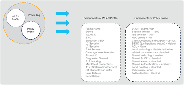
● WLAN profile: Defines the SSID name and security settings.
● Policy profile: Defines the policy to be associated to the WLAN. It specifies the settings for client VLAN, ACLs, QoS, Application Visibility and Control, session timeout, authentication, authorization, and accounting (AAA) override settings, and so on.
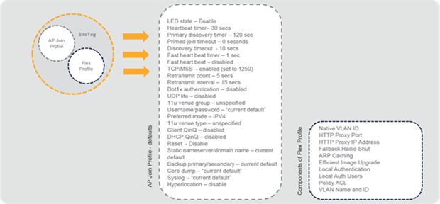
● AP join profile: Defines the settings related to the AP such as Control and Provisioning of Wireless Access Points (CAPWAP) and related timers, management access to the AP, etc.
● Flex profile: Defines the settings related to FlexConnect, such as VLANs, ACLs, etc.
● RF profile: Defines the RF characteristics of each band.
The tags allow you to bind the settings in the profiles to access points.
There are three types of tags:
● Policy tag: Binds the WLAN and the policy profile.
● Site tag: Assigns the AP join profile settings to the AP and determines if the site is a local site, in which case the APs will be in local mode or FlexConnect mode.
● RF tag: Binds the RF profiles of each band to the AP.
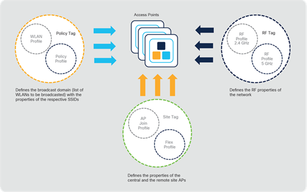
Elements of the Catalyst 9800 Series configuration model
Details of the configuration components of each profile type are provided in the Appendix of this document.
4.2 Association of tags to APs
Access points are tagged based on broadcast domain, the site they belong to, and the RF characteristics desired. Once tagged, the AP gets a list of WLANs to be broadcasted, along with the properties of the respective SSIDs. The AP is tagged with the default policy, site, and RF tags unless explicitly changed. When a tag associated with an AP is changed, the AP resets its CAPWAP connection.
5. Intra- and inter-controller roaming (Layer 3 roaming)
The Catalyst 9800 Series controllers based on Cisco IOS XE support seamless client roaming across access points managed by the same controller, between controllers in the same mobility group on the same subnet, and across controllers in the same mobility group on different subnets.
As described earlier, a fast secure roam of a wireless client occurs when the client roams between two APs (in local mode or in the same FlexConnect group) connected to the same controller. When the wireless client moves its association from one access point to another, the controller simply updates the client database with the newly associated access point. The client retains its IP address and the controller continues to forward the traffic of the wireless client to the VLAN to which the WLAN is mapped or to the VLAN to which the wireless client belongs in override scenarios.
Intra-controller, inter-policy tag roaming
However, there could be scenarios in which a wireless client roams between two neighboring buildings on campus that have RF coverage in the path of the roam. The access points in both buildings are served by the same Catalyst 9800 Series controller. However, the wired infrastructure is designed in a such a way that the VLAN assignments are different for the buildings. Here the SSID name and the WLAN profile remain the same, but there is a separate policy profile for each of the buildings, with the corresponding VLAN associated in the policy profile.
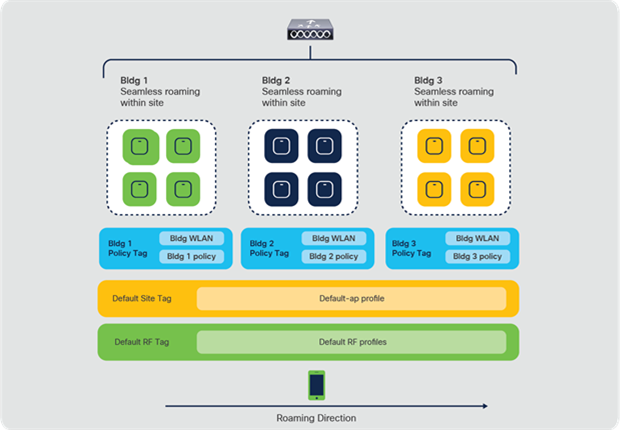
Catalyst 9800 Series controller with multiple policy tags
In the Catalyst 9800 Series controllers, a group of access points belonging to a floor, building, or location can be tagged with different policy, site, or RF tags, but can have the same WLAN profile. That is, the same SSID name can be advertised across all of the APs in the controller. A client could roam between two APs in the same controller that are configured with the same WLAN profile but associated with different policies. In such a scenario, the client is forced to go through a full authentication and DHCP process and renew its IP address.
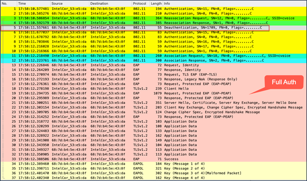
Packet capture – intra-controller inter-policy tag roam
As you can see from the packet capture, the client is forced into a deauthentication in an intra-controller but inter-policy tag scenario in which the policy profile is different.
Notes:
● A slow roam occurs only when either the name or the content of the policy profile is different.
● In a campus deployment with APs in local mode, the name or contents of a site tag or RF tag do not influence the seamless roam.
The Catalyst 9800 best practices guide describes different ways to overcome the issue of roaming between policy tags.
If the policy profiles differ only for certain parameters (VLAN and ACL), seamless roaming across policy tags can be achieved with the help of the VLAN-persistent feature. This feature is supported beginning with Cisco IOS XE Release 17.3.1 and can be enabled from the Command-Line Interface (CLI) in the global configuration mode, as shown below:
C9800-1(config)#wireless client vlan- persistent
Multiple controller deployments support client roaming across access points associated to different controllers but in the same mobility group. This roaming is transparent to the client because the session is sustained and a tunnel between controllers allows the client to continue using the same DHCP or client-assigned IP address as long as the session remains active.
The roaming can be either:
Intra-subnet: The WLAN is tied to the same VLAN/subnet in both the controllers
Inter-subnet: The WLAN is tied to a different VLAN/subnet in the two controllers
In the intra-subnet roam, the client context is completely handed off and traffic switching happens on the controller to which the client roamed.
In the inter-subnet roam, an Anchor <--> Foreign relationship is formed, wherein the client traffic is tunneled back to the controller from where it roamed and traffic is switched to the wired infrastructure from the anchor controller. The client entry is present in both controllers and is marked as Anchor in the controller from which it roamed and as Foreign in the controller to which it roamed.
Note: Please refer to Figures 2 and 3 in Section 1 for illustrations of intra- and inter-controller roaming.
The Catalyst 9800 Series controllers use CAPWAP-based tunnels for mobility. The mobility control channel will always be encrypted, and the mobility data channel can be optionally encrypted. This is referred to as secure mobility.
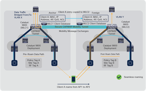
Catalyst 9800 Series inter-controller secure mobility tunnel
Note:
● For the inter-controller, intra-subnet roam, the policy has to be identical (VLAN). The policy profile name or policy tag name can be different, but the contents of the policy have to be same. If the VLAN is different in the policy, but the policy profile or policy tag name is still the same on both the controllers, the traffic is switched back to the controller from which the roam originated (anchor controller).
● If AAA Override is enabled, and the override VLAN is present on both controllers, the client state will be local (that is, an Anchor <--> Foreign relationship will not be formed) and traffic switching will happen in the controller to which it roamed.
● If AAA Override is enabled and the override VLAN is NOT present on the controller to which the client roams, the traffic will be tunneled back to the controller from which it roamed and the client state will be marked as Foreign in the controller to which it roamed and to Anchor in the controller from which it roamed.
● If the policy profile has ACL and QoS policies, or is obtained through AAA override, then in the inter-controller, inter-subnet roam (anchor, foreign), the QoS policy is applied on the foreign controller and the ACL policy is applied on the anchor controller.
Configuration steps:
Step 1. Mobility group name configuration
As a first step, configure the global parameters such as mobility group name and multicast address – in case you need to exchange the mobility messages through a multicast address. The mobility group name has to be same in all controllers where a seamless fast secure roam is desired.
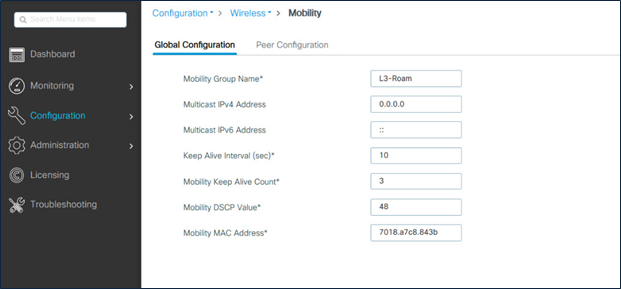
Catalyst 9800 Series mobility group configuration
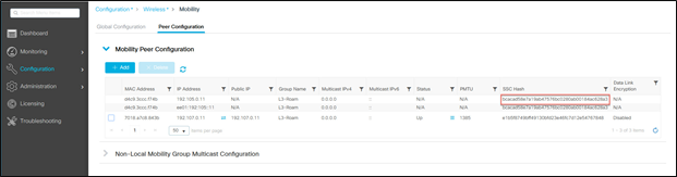
Step 2. Mobility peer configuration
Configure the mobility peers of all controllers participating in the mobility group. This needs to be repeated in all of the controllers.
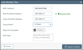
Catalyst 9800 Series mobility peer configuration
Note:
● Data link encryption is optional. It needs to be enabled if the mobility CAPWAP data tunnel will be encrypted.
● SSC hash is required if the peer controller is a Catalyst 9800-CL (hypervisor based), as it uses a self-signed certificate and SSC hash is used as an additional validation. SSC hash is not required if the peer is an appliance, as it will have a Manufacturer Installed Certificate (MIC).
Step 3. Mobility peer tunnel verification
The peer status has to be listed as Up in all the controllers.
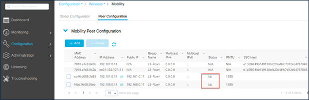
Catalyst 9800 Series mobility peer status
Now, when the client roams, the mobility history in the client details indicates the mobility role.
On the anchor controller:
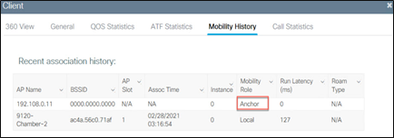
Catalyst 9800 Series inter-controller roam – client mobility history on the anchor controller
On the foreign controller:
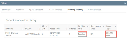
Catalyst 9800 Series inter-controller roam – client mobility history on the foreign controller
If the roam performed was an inter-controller, intra-subnet roam, the Mobility Role will be Local, and Roam Type will indicate the fast secure roam method used.
At times, you may need to configure a static IP address for wireless clients. When these wireless clients move in the network, they might try associating with other APs belonging to a different policy tag or with controllers on a different subnet than the static IP. In these scenarios, the wireless clients will fail to connect to the network. The static IP mobility feature helps enable the mobility of wireless clients with static IP addresses. The traffic from the wireless client with a static IP address is tunneled back to the controller to which the wireless client initially associated and that has the same subnet as the static IP wireless client.
Configuration steps:
Under Policy Profile Ò Mobility, enable Static IP Mobility in the policy profile for all the controllers to which the client is expected to roam.
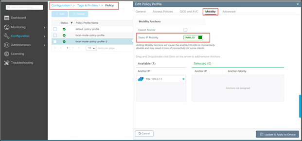
Static IP mobility configuration
Note:
There are certain restrictions on this feature:
● IPv6 is not supported.
● FlexConnect mode is not supported.
● WebAuth (Local Web Authentication [LWA] and Central Web Authentication [CWA]) is not supported.
● It is supported only on open, PSK, and 802.1X WLANs.
● It is supported only when all the peers are configured for static IP mobility in the policy profile.
● It is supported only on WLANs have not enabled the mobility anchor configuration. If the mobility anchor configuration for the WLAN is enabled, the static IP mobility feature is not supported.
● Inter-Release Controller Mobility (IRCM) with AireOS controllers is not supported.
● In the Catalyst 9800 Series, intra-controller Layer 2 roaming occurs when the client roams between APs having the same policy tags. If the policy tags differ between the APs due to the policy profile content being different in different VLANs, the seamless client roam will fail. This can be overcome with the “client-vlan-persistent” command in the configuration mode.
● Inter-controller Layer 2 roaming occurs when the client VLAN associated to the SSID is the same on both controllers. When the client roams to an access point on a different controller, the new controller exchanges mobility messages with the original controller (where the client was initially present and roamed from) and the client database entry is moved to the new controller. New security context and associations are established if necessary and the client database entry is updated for the new access point.
● Inter-controller Layer 3 roaming occurs when the client VLANs associated to the SSID are different on each controller. Layer 3 roaming is similar to Layer 2 roaming in that the controllers exchange mobility messages on the client roam. However, instead of moving the client database entry to the new controller, the original controller marks the client with an “Anchor” entry in its own client database. The database entry is copied to the new controller client database and marked with a “Foreign” entry in the new controller. The roam remains transparent to the wireless client, and the client maintains its original IP address.
● On the Catalyst 9800 Series controllers, the decision for Layer 2 versus Layer 3 roaming is independent of the client subnet mapped to the client VLAN; only the VLAN matters in deciding the type of roam. This is because the Catalyst 9800 Series doesn’t require a Layer 3 interface to be configured for each client VLAN. If an inter-controller Layer 2 roam is desired, it’s the user’s responsibility to make sure that the network is configured so that the same IP subnet is associated to the same VLAN on both wireless controllers.
6. Catalyst 9800 to AireOS inter-release controller mobility
As customers migrate from AireOS controllers to the next-generation Catalyst 9800 Series controllers based on Cisco IOS XE, they expect that seamless mobility and services will work with different software and controllers in the Cisco Unified Wireless Network architecture.
This interoperability is referred to as Inter-Release Controller Mobility (IRCM).
Catalyst 9800 Series controllers use CAPWAP-based tunnels for mobility, whereas AireOS-based controllers predominantly use Ethernet over IP (EoIP). To interoperate with Catalyst 9800 Series controllers, secure mobility-based mobility tunnels were introduced in AireOS Release 8.8.111.0 and above. To support the interoperability with the previous-generation widely deployed Cisco 5508 Wireless Controller, secure mobility has been added in special releases of the 8.5 release train.
Note: AireOS 8.5 is the last release to support the 5508 and 8510 controllers.
Note: The Catalyst 9800 Series does not support IRCM with the following platforms:
● Cisco 2504 Wireless Controllers
● Cisco Wireless Services Module 2 (WiSM 2) controllers
● Cisco Flex® 7510 Wireless Controllers
The inter-controller roaming between Catalyst 9800 and AireOS-based controllers is only Layer 3 roaming. This means that even if the WLANs are mapped to the same VLAN between these two types of controllers, the wireless client will always be anchored to the controller from which it originated the roam.
Note: IRCM is also supported for guest anchor scenarios with the supported software releases and controller platforms. Catalyst 9800 Series or AireOS controllers can act as guest anchors.
As a best practice, we recommend having the WLANs mapped to different VLANs in the different types of controllers.
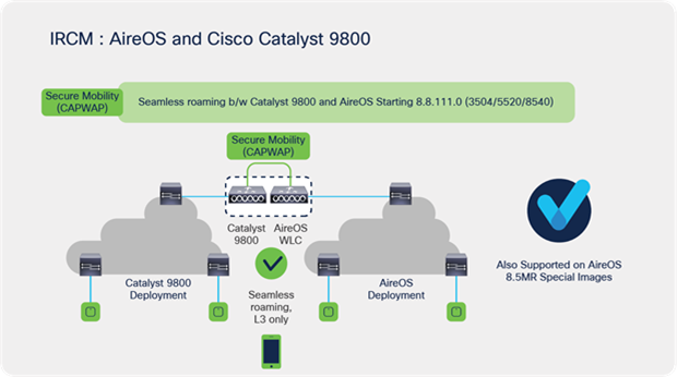
Catalyst 9800 and AireOS IRCM
In scenarios with deployments that have controllers not supported for IRCM, or that are running an older software release, it is enough for one of the AireOS controllers in the path of the roam to be upgraded to an IRCM-supported image, as depicted in the figure below.
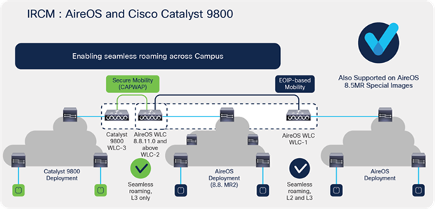
Catalyst 9800 and AireOS IRCM – seamless roaming across campus
WLC 1: Any AireOS controller running the 8.2, 8.3, or 8.5 release image.
WLC 2: Any AireOS 3504, 5520, or 8540 controller running Release 8.8.111.0 and above. The WLC can also be a 5508 or 8510 controller running a Release 8.5-based IRCM-supported image.
WLC 3: Any Catalyst 9800 Series controller.
WLC 2 (running Release 8.8.111.0 and above or a Release 8.5-based IRCM-supported image) can do both EoIP and secure mobility on a per-peer basis and can pair up with WLC 1 (older AireOS software releases) and WLC 3 (Catalyst 9800 Series controller).
Seamless client roaming is possible between WLC 1 and WLC 2 in both Layer 2 and Layer 3 roaming.
Seamless client roaming is possible between WLC 2 and WLC 3 only in Layer 3 roaming.
Seamless client roaming is not possible between WLC 1 and WLC 3.
Table 3. IRCM platform compatibility matrix
| Platform |
Software release train |
| 2504 |
IRCM not supported |
| 3504 |
AireOS Release 8.8.111.0 and above, AireOS Release 8.5.164.0 and 8.5.164.126 (IRCM release) |
| 5508 |
AireOS Release 8.5.164.0 and 8.5.164.126 (IRCM release) |
| WiSM2 |
IRCM not supported |
| Flex 7510 |
IRCM not supported |
| 8510 |
AireOS Release 8.5.164.0 and 8.5.164.126 (IRCM release) |
| 5520 |
AireOS Release 8.8.111.0 and above, AireOS Release 8.5.164.0 and 8.5.164.126 (IRCM release) |
| 8540 |
AireOS Release 8.8.111.0 and above, AireOS Release 8.5.164.0 and 8.5.164.126 (IRCM release) |
| vWLC |
IRCM not supported |
Note: Please refer to the following document for the complete software compatibility matrix for IRCM between Cisco IOS XE and AireOS.
Configuration steps:
Configuring the mobility tunnel on the Catalyst 9800 Series controller is the same as described in the previous section.
Mobility configuration in an AireOS controller:
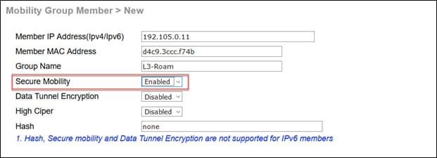
Secure mobility configuration for an AireOS mobility group
Note:
● The group name has to match to create the mobility group for fast secure roaming.
● Secure mobility has to be enabled for IRCM to work.
● Data tunnel encryption is optional. If the network is built on top of a nontrusted network, we recommend enabling data tunnel encryption. It has to be enabled on both sides.
● Hash is needed only when peering with a Catalyst 9800-CL (hypervisor-based controller). The hash can be obtained from the mobility peer configuration in the Catalyst 9800-CL controller GUI or by using the command “show wireless management trustpoint.”
Catalyst 9800-CL SSC hash
7. Additional reading and references
The following documents are suggested for additional reading and reference.
● Cisco Catalyst 9800 Series Best Configuration Practices: https://www.cisco.com/c/en/us/products/collateral/wireless/catalyst-9800-series-wireless-controllers/guide-c07-743627.html#Prerequisites
● Cisco Wireless Solutions Software Compatibility Matrix: https://www.cisco.com/c/en/us/td/docs/wireless/compatibility/matrix/compatibility-matrix.html
● Cisco Catalyst 9800 Recommended Releases: https://www.cisco.com/c/en/us/support/docs/wireless/catalyst-9800-series-wireless-controllers/214749-tac-recommended-ios-xe-builds-for-wirele.html
● 802.11 WLAN Roaming and Fast Secure Roaming on Cisco Unified Wireless Network (written for AireOS controllers): https://www.cisco.com/c/en/us/support/docs/wireless-mobility/wireless-lan-wlan/116493-technote-technology-00.html#anc21
● Cisco Catalyst 9800 Wireless Controller – AireOS IRCM Deployment Guide: https://www.cisco.com/c/en/us/td/docs/wireless/controller/technotes/8-8/b_c9800_wireless_controller-aireos_ircm_dg.html
8.1 Components of the policy tag
Catalyst 9800 Series configuration model – components of the policy tag
8.2 Components of the site tag
Catalyst 9800 Series configuration model – components of the site tag
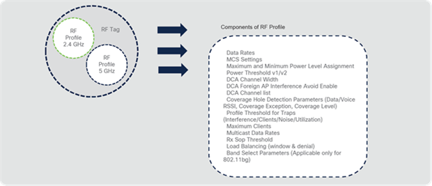
Catalyst 9800 Series configuration model – components of the RF tag