Cisco Wireless CW9174 Series Access Point Deployment Guide
Available Languages
Bias-Free Language
The documentation set for this product strives to use bias-free language. For the purposes of this documentation set, bias-free is defined as language that does not imply discrimination based on age, disability, gender, racial identity, ethnic identity, sexual orientation, socioeconomic status, and intersectionality. Exceptions may be present in the documentation due to language that is hardcoded in the user interfaces of the product software, language used based on RFP documentation, or language that is used by a referenced third-party product. Learn more about how Cisco is using Inclusive Language.
- US/Canada 800-553-2447
- Worldwide Support Phone Numbers
- All Tools
 Feedback
 Feedback
Cisco Wireless CW9174x Overview
The Cisco Wireless CW9174x is Cisco’s mid tier Wi-Fi 7 Access Point Platform with a penta radio architecture providing the full capability of Wi-Fi 7 Features based on 802.11be amendment such as 4K Modulation, Multi Link Operation (MLO), 320 MHz channel width, Pre-amble puncturing, Multi Resource Units, compressed block ack enhancements of up to 512 MPDUs and Wi-Fi Protected Access 3 (WPA3) security, all while being able to leverage advanced RF visibility with Cisco CleanAir® Pro together with an artificial intelligence and machine learning (AI/ML)-driven scanning radio.
The Cisco Wireless CW9174x is a Unified Product with one SKU, that can be deployed with a Cisco Wireless LAN Controller or Meraki Cloud based deployments. The CW9174x access can be deployed anywhere in the world just with the single SKU and avoids the need to buy a region or country specific SKU based on regulatory domain.
The Cisco Wireless CW9174x supports the entire Cisco Catalyst wireless stack functionality with Cisco Catalyst Center (Automation and Assurance), Cisco Spaces (Location and IoT), Identity Services Engine (security), and more. Throughout this guide, you will learn how the CW9174x is a wireless powerhouse that can take your network to the next level.
Table 1. Software support matrix
| Software release type |
Release version |
| Cisco IOS XE |
17.18.2 and later |
| Meraki MR |
32.1.5 and later |
Supported Controller platforms
CW9174x APs are supported with the following Catalyst 9800 Series Controllers:
● 9800-H1
● 9800-H2
● 9800-M
● 9800-80
● 9800-40
● 9800-L
● 9800-CL
Note: Embedded wireless controller on AP (EWC) functionality is not supported on the CW9174x, both as an active EWC or a subordinate AP.
Table 2. CW9174x At a Glance
| Capability |
Details |
| Product ID |
CW9174x – CW9174I (Internal Antenna) & CW9174E (External Antenna) |
| Scale |
768 Clients (256 clients per radio) |
| Serving Radio |
· 2.4 GHz (Slot 0), 2x2:2 spatial streams
· 5 GHz (Slot 1), 4x4:4 spatial streams
● 6 GHz (Slot 3), 4x4:4 spatial stream
(OR)
● 2.4 GHz (Slot 0), 4x4:4 spatial streams
· 5 GHz (Slot 1), 4x4:4 spatial streams
Note: Default – Tri-band Radio configuration, in countries where 6 GHz is supported
|
| IoT Capabilities |
● Dedicated 2.4 GHz IoT Radio
● Application Hosting Capabilities
|
| Scanning Radio |
Yes |
| Wi-Fi 7 Features |
● 4K QAM
● 320 MHz Channel Width
● Multi-Link Operation
● Preamble Puncturing
● Multi Resource Units
● Compressed Block Ack with 512 MPDUs
● UL Triggered OFDMA
|
| Wi-Fi 6 Features |
● MU-MIMO
● OFDMA
● BSS Coloring
● TWT
|
| LAN Port |
POE-IN 5 Gig mGig Port |
| Ports |
mGig, Console, USB, DC 54V |
| Antenna |
Omnidirectional – Integrated with CW9174I Omnidirectional & Directional – External with CW9174E · PID for Omni-Directional : CW-ANT-T-O2-D8 · PID for Directional : CW-ANT-T-D2-D8 |
| Dimensions |
8.9 x 8.9 x 2.5 inches 22.6 x 22.6 x 6.3 cm |
| Weight |
CW9174I - 3.36 lb (1.52 kg) CW9174E – 3.26 lb (1.47 kg) |
| USB |
9W Output |
| SSIDs |
● 2.4 GHz: 16
● 5 GHz: 16
● 6 GHz: 16
|
| MTBF |
CW9174I
· 25C : 2,445,523
· 50C : 1,349,582
CW9174E
· 25C: 2,410,715
· 50C: 1,303,895
|
| Environment |
CW9174I :
● Non-operating (storage) temperature: -22° to 158°F (-30° to 70°C)
● Non-operating (storage) altitude test: 25°C (77°F) at 15,000 ft (4570 m)
● Operating temperature: 32° to 122°F (0° to 50°C)
● Operating humidity: 10% to 90% (noncondensing)
● Operating altitude test: 40°C (104°F) at 9843 ft (3000 m)
CW9174E:
● Non-operating (storage) temperature: -22° to 158°F (-30° to 70°C)
● Non-operating (storage) altitude test: 25°C (77°F) at 15,000 ft (4570 m)
● Operating temperature: -4° to 122°F (-20° to 50°C)
● Operating humidity: 10% to 90% (noncondensing)
● Operating altitude test: 40°C (104°F) at 9843 ft (3000 m)
|
| Antenna Gain |
9174I
● 2.4 GHz: 5 dBi
● 5 GHz: 5 dBi
● 6 GHz: 6 dBi
● IoT: 4 dBi
9174E (Omni-Directional, CW-ANT-T-O2-D8)
● 2.4 GHz: 2 dBi
● 5 GHz: 5 dBi
● 6 GHz: 5 dBi
● IoT: 2 dBi
9174E (Directional, CW-ANT-T-D2-D8)
● 2.4 GHz: 6.6 dBi
● 5 GHz: 5.7 dBi
● 6 GHz: 5.7 dBi
● IoT: 6 dBi
|
Table 3. Serving Radio Specifications
| Mode |
2.4 GHz Slot 0/ 5 GHz Slot 0 |
Primary 5 GHz (Slot 1) |
6 GHz (Slot 2) |
| Tri-radio, Tri-Band 10SS |
● 2x2:2SS
● (20 MHz)
|
● 4x4:4SS
● (20/40/80/160 MHz)
|
● 4x4:4SS
● (20/40/80/160/320 MHz)
|
| Dual-radio Dual Band 8SS |
● 4x4:4SS
● (20 MHz)
|
● 4x4:4SS
● (20/40/80/160 MHz)
|
● 4x4:4SS
● (20/40/80/160/320 MHz)
|
The Cisco Wireless 9174x is interoperable with the following network management and security solutions.
Table 4. Software Interoperability
| Catalyst 9800 |
Cisco Catalyst Center |
Cisco Spaces: Connector |
Cisco ISE |
| 17.18.2 |
2.3.7.10/3.2.1 |
Release 3 |
3.4 |
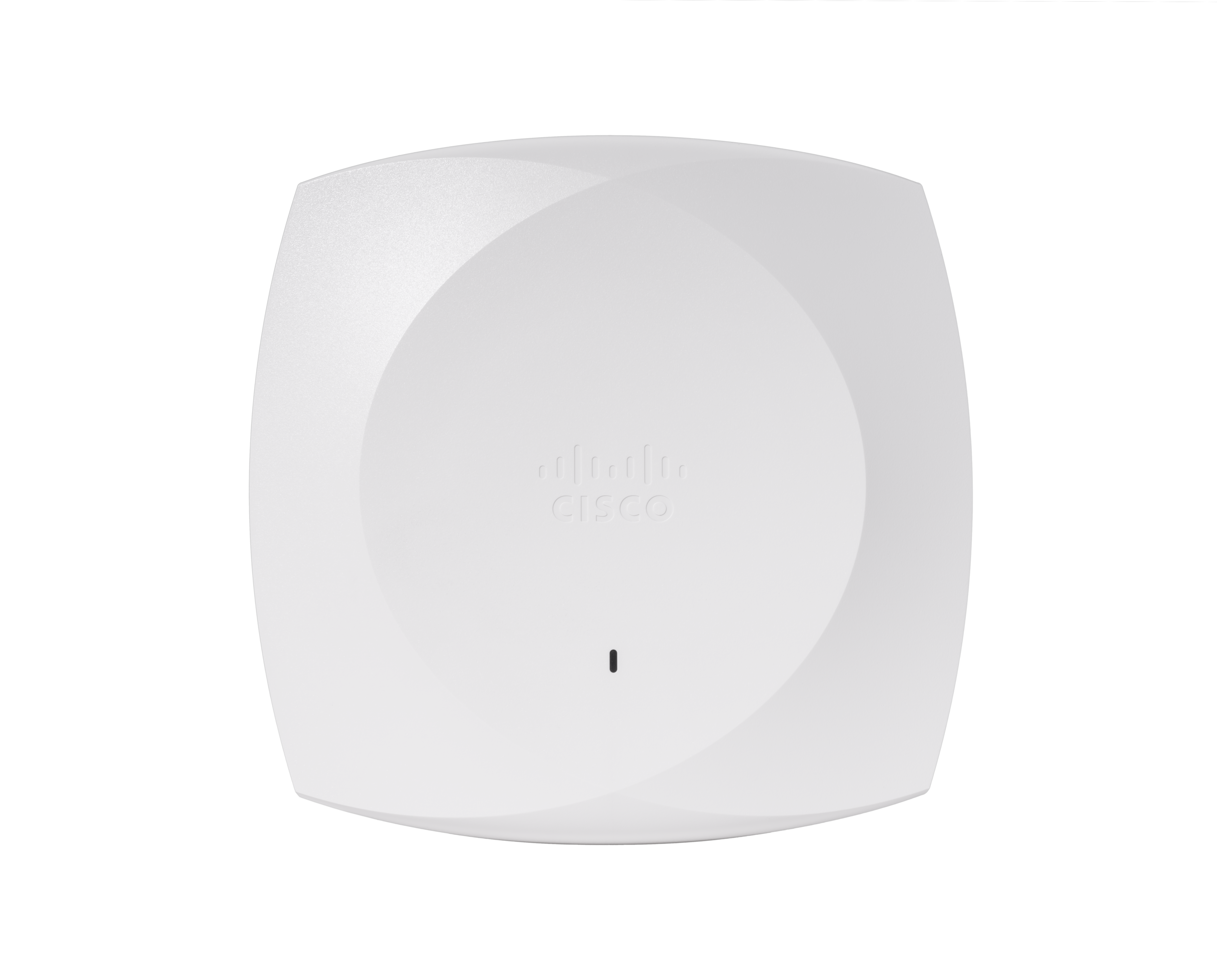
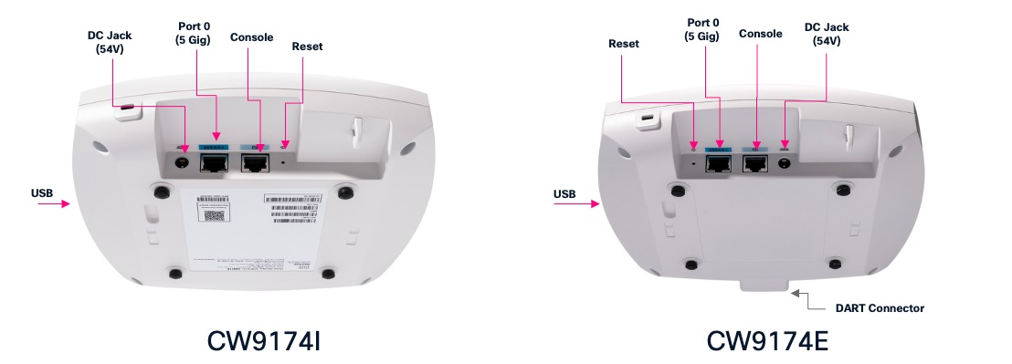
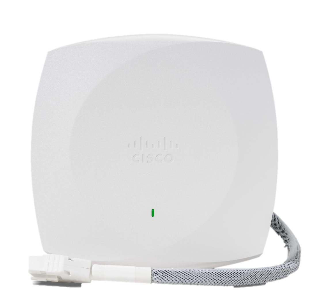
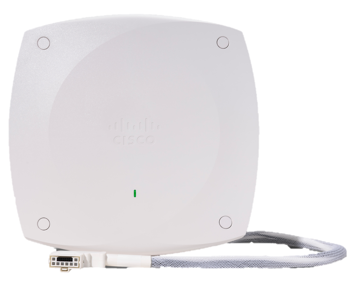
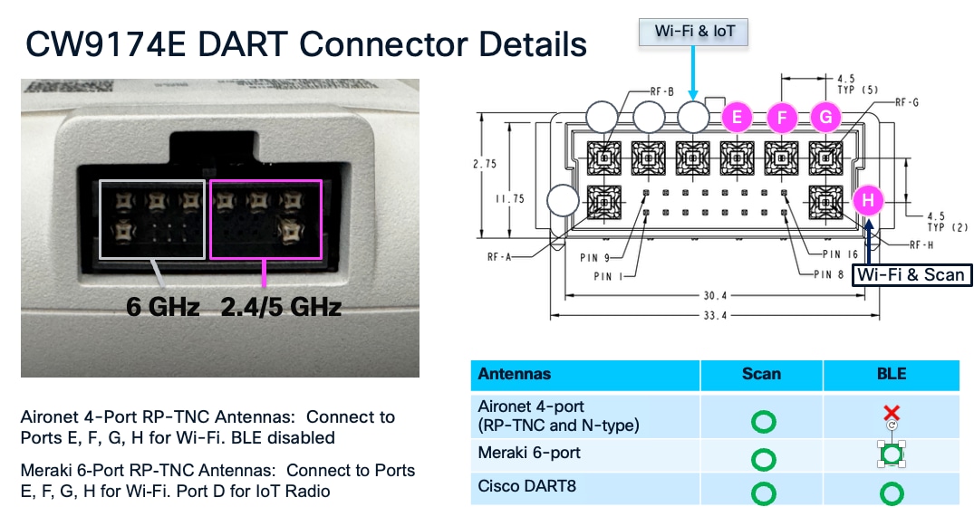
The CW9174x has an altogether new design which is aesthetically appealing allowing you to identify it among other APs instantly. The CW9174E has a DART8 connector
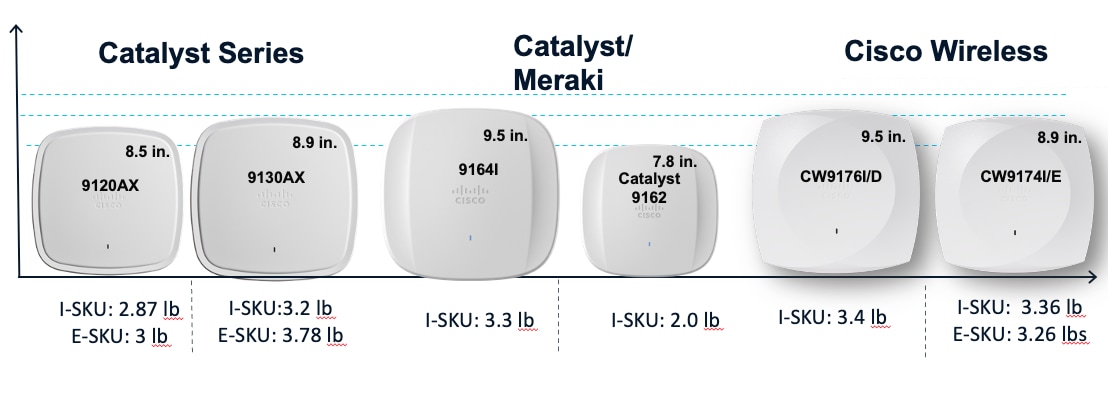
The CW9174x Wi-Fi 7 AP is similar in size and weight to the mid-range and high-end Catalyst Wi-Fi 6 and Wi-Fi 6E APs and smaller and lighter than many of the Cisco Catalyst APs prior to Wi-Fi 6. However, it boasts a much more robust penta-radio architecture, a dedicated scanning radio, a dedicated IoT radio, , 5 Gig Multigigabit ports, and supports Wi-Fi 7.
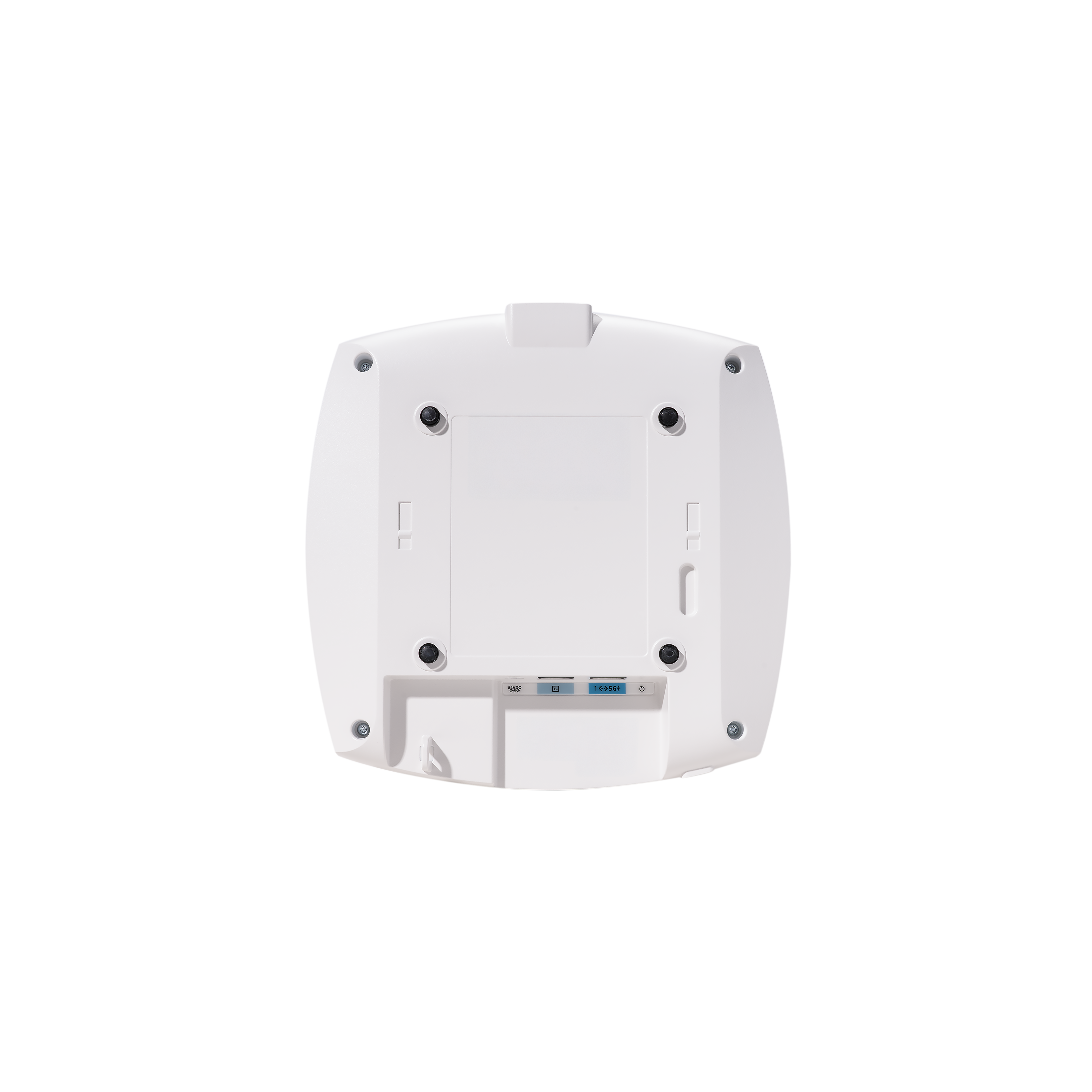
The following figures depict the ports and reset button on the CW9174x:
External Antennas
The CW9174E supports three new external Antennas.
1. An Omnidirectional antenna (CW-ANT-T-O2-D8) with an antenna gain of 2 dBi on 2.4 GHz, 5 dBi on 5 GHz and 6 GHz radios. The can be ceiling mounted and connected to the Access Point using the DART8 connector.
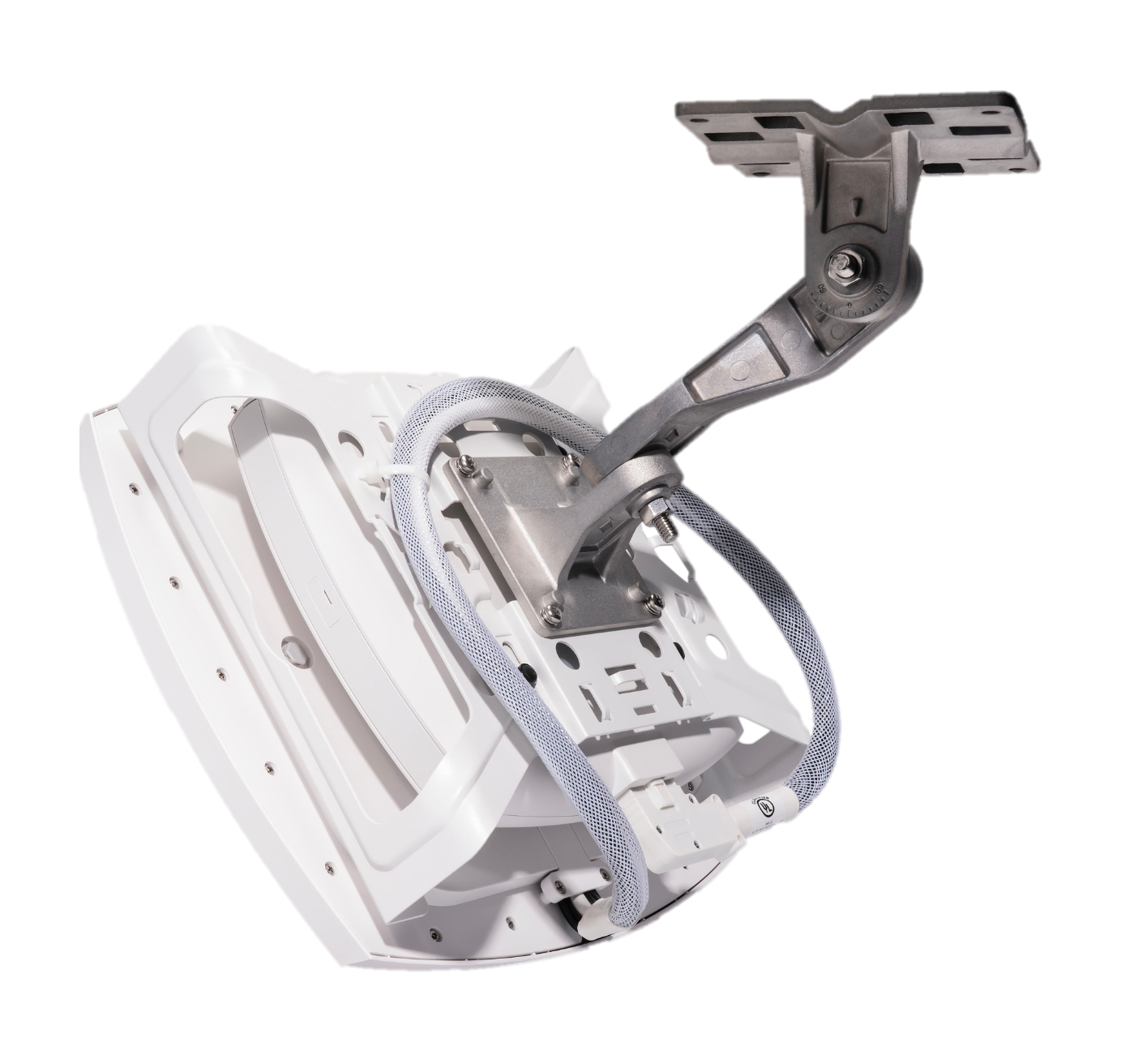
2. A Directional patch antenna (CW-ANT-T-D2-D8) with a 75x75 coverage and antenna gain of 6 dBi for for all the three bands. This can be ceiling, wall or pole mounted using an Articulating Arm (CW-MNT-ART2-00) or can be integrated into one unit using an Integrated AP mount (CW-MNT-9).
Both the above antennas have a built in Accelerometer to detect the AP’s down tilt angle and orientation sensing primarily for post deployment verification through the Wireless LAN Controller UI and Meraki Dashboard.
3. An omnidirectional dipole antenna with RP-TNC connector and an antenna gain of 3 dBi on 2.4 GHz and 5 dBi on 5 and 6 GHz.
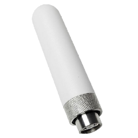
a. The use of this antenna will require the following accessory:
i. For tri-band, 10 spatial stream operation: AIR-CAB002-D8-R=, 8-port Smart Antenna Connector to RP-TNC Connector cable
ii. For dual band, 8 spatial stream operation: CW-CAB-001-D8-R4, 8-port Smart Antenna Connector to 4-port RP-TNC connector
b. A mounting bracket will need to be procured, custom fabricated or 3D printed for your specific use case. Cisco currently does not offer mounting brackets for this antenna for use with the CW9174E
c. Antenna ports A, B, C, D are 6GHz ports and E, F, G, H, are 2.4 and 5GHz dual band ports. As a general guidance, the antennas should be kept 5 inches from each other for proper isolation.
Note: For assembly and mounting instructions, please refer to the Hardware Installation Guide. Link provided in the reference section of this document.
The CW9174E also supports the following legacy Antennas
AIR-ANT2524V4C-R/RS*&
AIR-ANT2544V4M-R/RS*&
AIR-ANT2566P4W-R/RS*&
AIR-ANT2566D4M-R/RS*&
AIR-ANT2513P4M-N/NS*&
C-ANT9101&
C-ANT9102
C-ANT9103
MA-ANT-3-C6&
MA-ANT-3-D6&
MA-ANT-3-E6&
MA-ANT-3-F6&
* IoT radio disabled when used with this antenna.
& 2.4 GHz and 5 GHz only when used with this antenna.
Note: CW9174E is an External Antenna AP and the use of this AP in 6 GHz is permitted only in Standard Power Mode in US (FCC) and Canada (ISED). In other countries, the use of an external Antenna AP is not permitted in 6 GHz band and will be restricted only to dual band. Please refer to the deployment instructions for AFC in On-Prem (Catalyst) and Cloud (Meraki) modes with the links provided in the reference section.
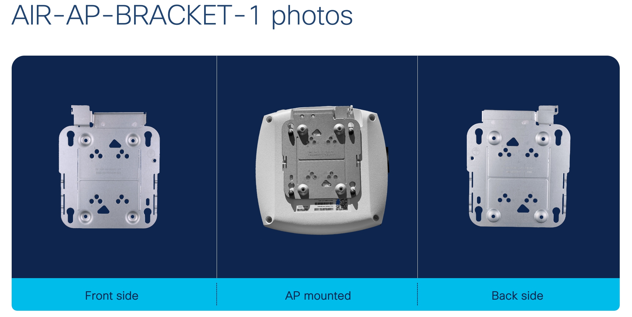
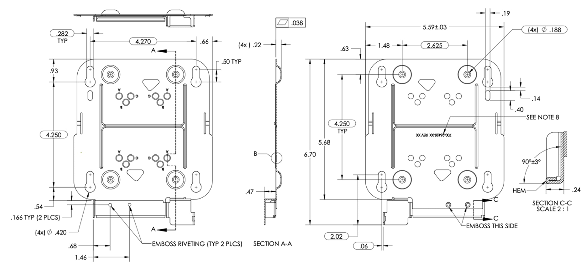
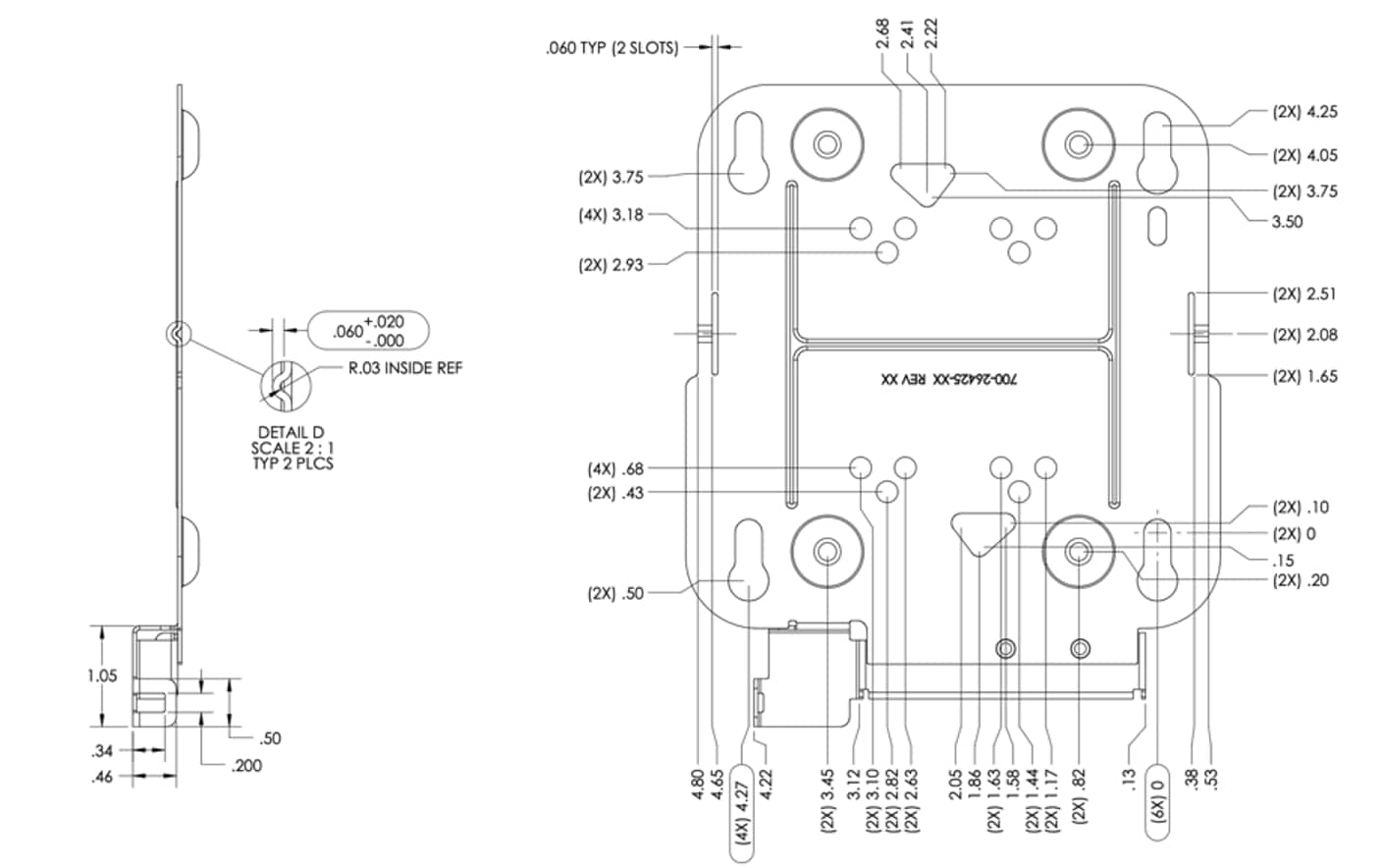
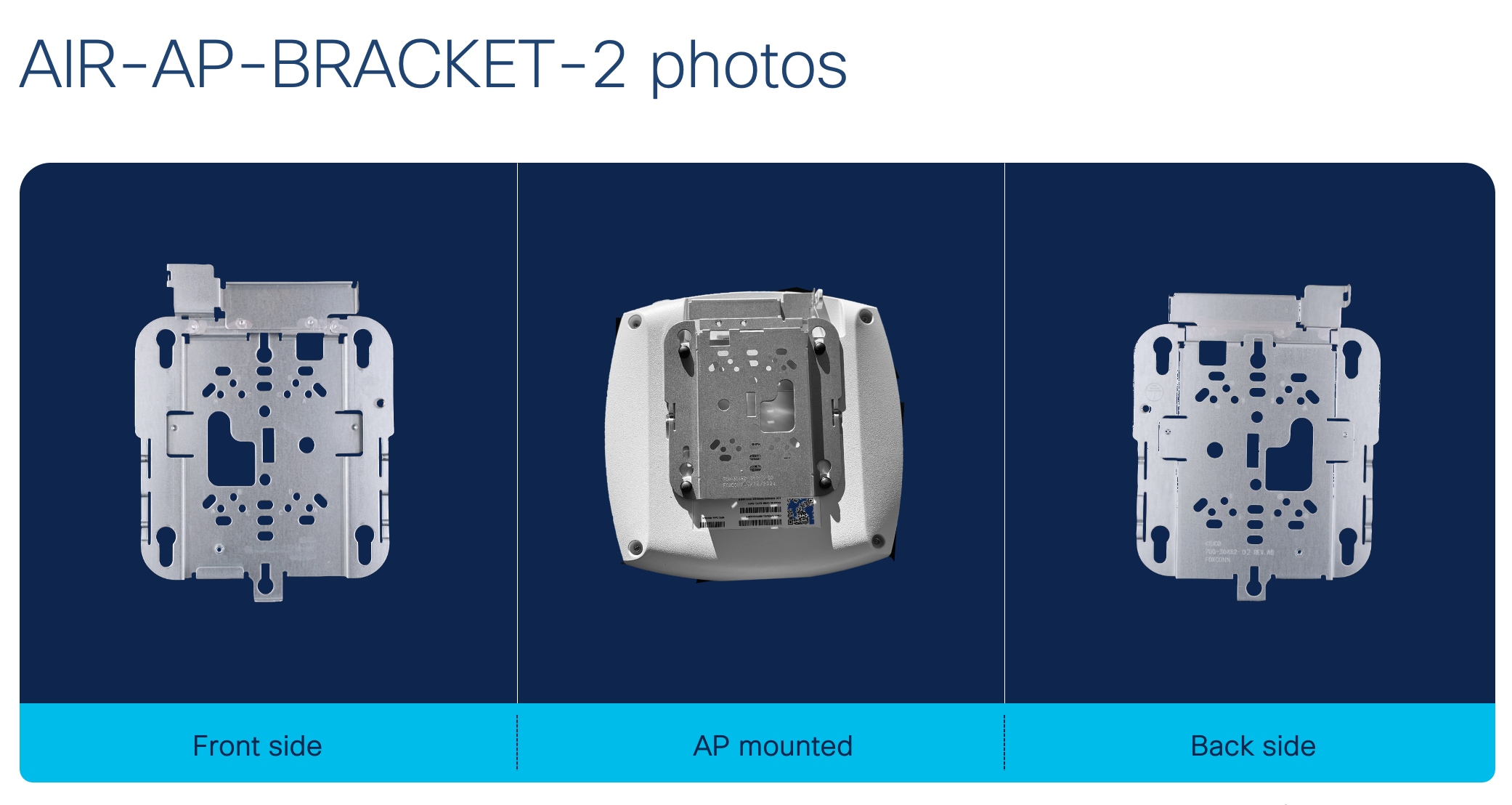
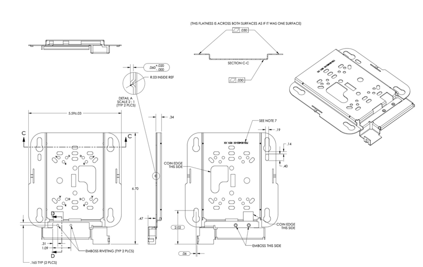
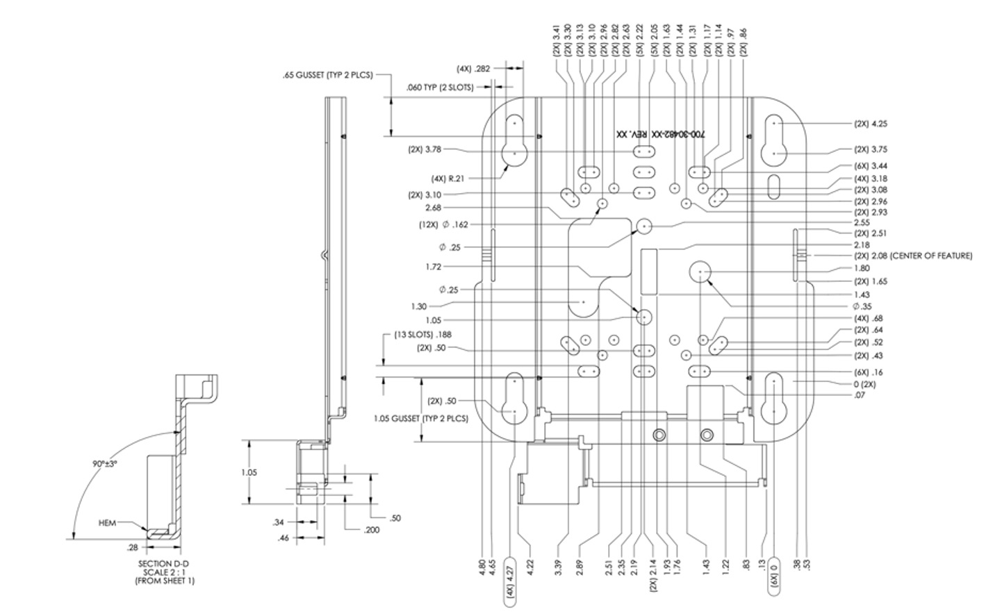
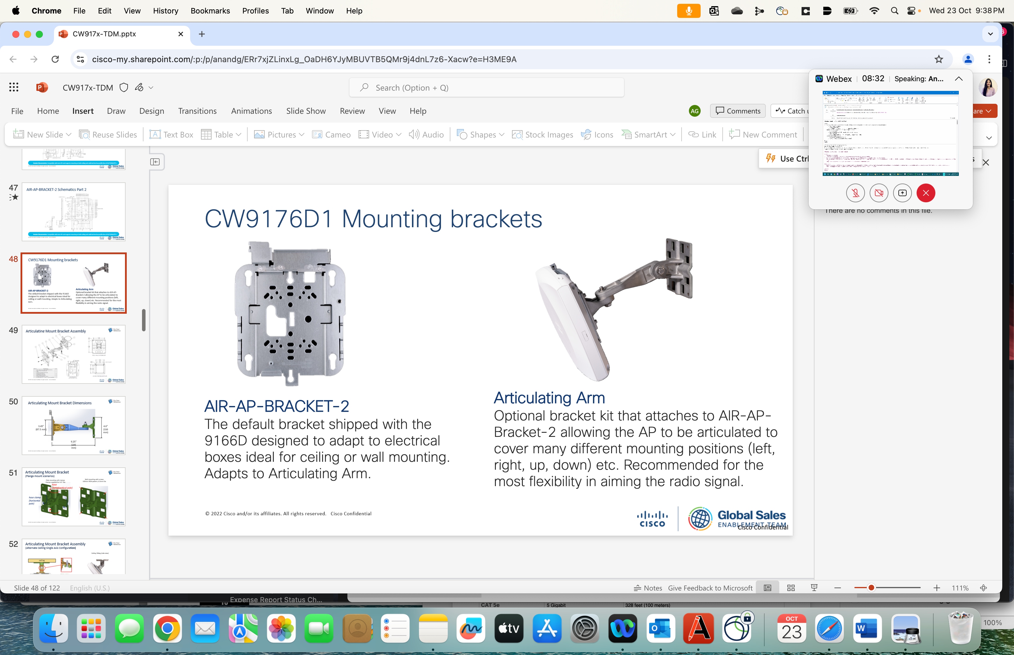
The CW9174x is compatible with the Cisco Low Profile Mounting Bracket AIR-AP-BRACKET-1 (default option) and Cisco Universal Mounting Bracket AIR-AP-BRACKET-2 mounting brackets. This AP is also compatible with the AIR-AP-T-RAIL-R and AIR-AP-T-RAIL-F for T-rail drop ceiling. These brackets are the same AP brackets provided for all Tier 2 and 3 enterprise-class APs for the last 15+ years. This backward compatibility streamlines the day-0 process for brownfield deployments, allowing the CW9174x to be mounted on existing brackets. The CW9174x can be mounted using the AIR-CHNL-ADAPTER clip for channel-rail ceiling grid profiles.
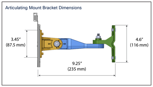
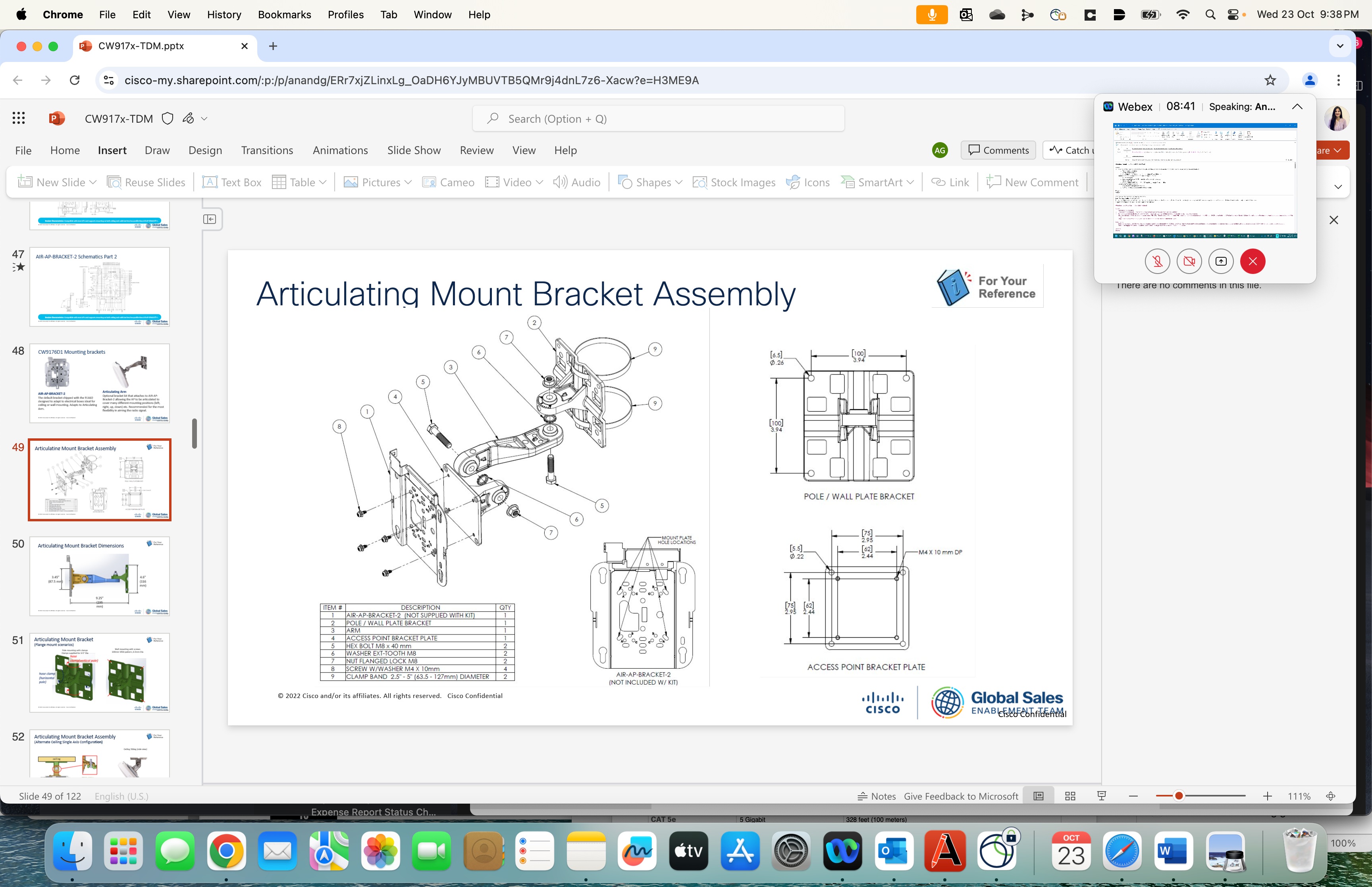
The external Antenna of CW9174E can be mounted on the articulating mount CW-MNT-ART2-00 or the Integrated Antenna and AP Mount CW-MNT-9
For more details on mounting the access point, please refer to the Hardware Installation Guide. Link provided in the reference section of this document.
The following figures provide details about the AIR-AP-Bracket-1 and AIR-AP-Bracket-2 for reference:
Use cases for CW9174E
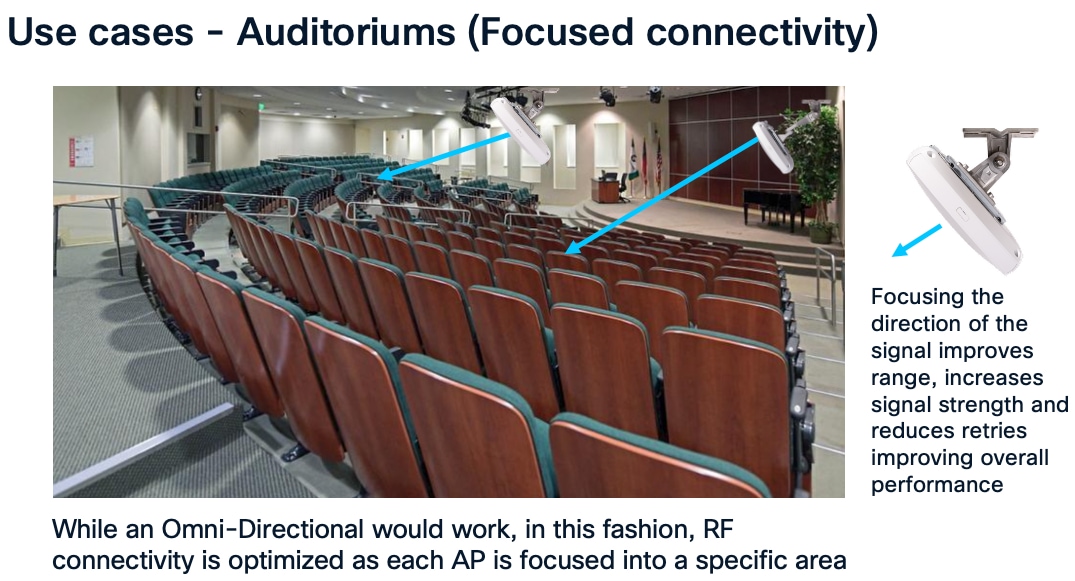
CW9174E is an ideal product for auditoriums and other places where focused connectivity is desired.
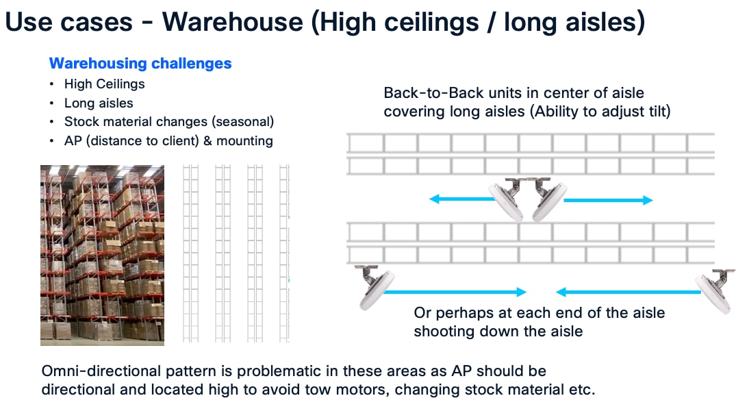
CW9174E is an ideal product for warehouse environment where focused connectivity is desired.
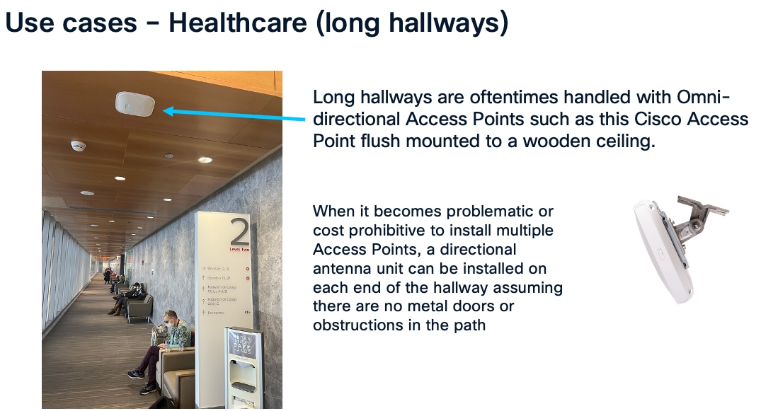
CW9174E can be wall mounted instead of traditional ceiling mounted Access Points when the desire is to cover long hallways.
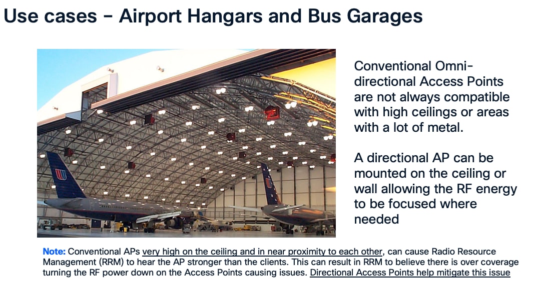
CW9174E can be used in areas with really high ceilings as the directional antenna can focus downward into a given area.
It is recommended when mounting Access Points to locate them as close to the users as possible, in the case of extremely high ceilings, Access Points with directional antenna arrays such as the CW9174E can improve the range of the client allowing the antenna to be mounted typically higher than the recommended distance of 10-15 Feet. Always be sure to test the connectivity during the installation process when the ceiling height exceeds 18 Ft.
Also, when co-locating units especially in close proximity, it is a good practice to test both units operating concurrently at heavy load (and then test each unit individually at heavy load) to verify the units are not interfering with each other. Whenever a unit is in close proximity of another unit (always try to space the operating channels <frequencies> as far apart as practical) verify any degradation that may occur is acceptable if not try reducing RF power or relocating the units. Anytime a unit is in very close proximity to another unit the potential of RF degradation (desense) can occur.
The use of proper cable types will enhances the performance of the CW9174x. Since this AP has 5-Gbps ports, it is recommended to use either CAT6 or CAT 6a cable which support speeds of up to 10 Gbps. CAT 5e cables can still be used; however, the AP’s performance may get degraded.
The table below lists the various cable types that can be used with the CW9174x.
Table 5. Cable Types Supported
| Cable Type |
Speeds |
Maximum Length |
| CAT 5e |
5 Gigabit |
328 feet (100 meters) |
| CAT 6 |
1/2.5/5 Gigabit |
330 feet (100 meters) |
| 10 Gigabit |
164 feet (50 meters) |
|
| CAT 6a |
10 Gigabit |
330 feet (100 meters) |
The following table depicts the radio, port, USB performance, and maximum power draw based on the AP’s input power. For optimal performance, 803.2bt is required.
Note: It’s recommended to use Cat 6 or Cat 6A cables for the best performance.
Table 6. PoE specifications for CW9174x
| Power Source |
Number of Spatial Streams |
2.4 GHz Radio (Slot 0) |
5 GHz Radio (Slot 1) |
6 GHz Radio (Slot 3) |
mGig Link Speed |
USB |
IoT/Scan Radio |
| 802.3 af (PoE) |
1 |
1x1 |
Disabled |
Disabled |
1G |
Disabled |
N |
| 802.3 at (PoE+) =< 30W |
10 |
2x2 |
4x4 |
4x4 |
2.5 G |
Y/2.5W |
Y |
| 802.3 at (PoE+) =< 30W |
8 |
4x4 |
4x4 |
Disabled |
2.5 G |
Y/2.5W |
Y |
| 802.3 bt Class 5 (UPOE) or DC Power |
10 |
2x2 |
4x4 |
4x4 |
5 G |
Y/9W |
Y |
| 802.3 bt Class 5 (UPOE) or DC Power |
10 |
4x4 |
4x4 |
Disabled |
5 G |
Y/9W |
Y |
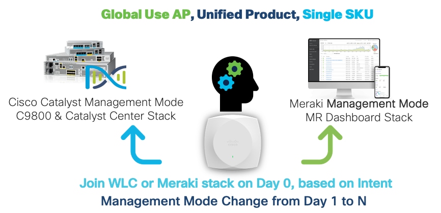
The CW9174x is a unified product, global use access point, that can be deployed with Cisco Catalyst 9800 Wireless LAN Controller (a.k.a Catalyst Management Mode) or cloud-based deployment with Meraki Wireless Stack (a.k.a Meraki Management Mode) anywhere in the world, where it’s certified to use without the need for a regulatory domain specific SKU. This gives customers the flexibility and investment protection, when they decide to deploy the Access Point in any of the deployment model.
The CW9174x can discover the management mode based on the customer’s intent by the presence of cloud connectivity and discovery options based on DHCP and DNS. Once the Access Point discovers the controller, it can obtain its country specific regulation through 1) GPS/GNSS based geo-location (if an external GPS/GNSS Antenna is plugged to the CW9174x) 2) proximity based discovery or 3) through a regulatory activation file for air-gapped deployments.
Refer to the Cisco Wireless Global Use Access Points Deployment Guide for a detailed explanation and configuration options to achieve the desired management mode discovery.
The IEEE developed the 802.11be amendment (a.k.a “Extremely High Throughput”) to the 802.11 standard, which the Wi-Fi alliance adopted the draft v3.0, as the basis for Wi-Fi 7 certification. The Wi-Fi 7 alliance planned to adopt a subset of features from the 802.11be amendment as part of their Release 1 certification, that was made available in January 2024. A second release with support for incremental set of features is planned for Release 2 certification, slated for December of 2025.
Wi-Fi 7 offers many enhancements that will benefit enterprises, as well as end users by increasing speeds up to four times compared to Wi-Fi 6. In addition, it offers super low latency, more robust connection, higher spectral efficiency, better interference mitigation, more power-saving techniques, better roaming experience, and increased security.
Wi-Fi 7 in essence, brings in the following features.
● 4096 QAM (a.k.a 4K-QAM) – encodes the number of bits in a sub-carrier to 12 bits, in contrast to 10 bits encoded in a sub-carrier for 1024 QAM in Wi-Fi 6. This introduces two new MCS rates MCS 12 and 13. 4K QAM helps upto 20% higher data transmission rates.
● 320 MHz Channel Width (at 6 GHz) - The max channel width is doubled to 320 MHz when compared to 160 MHz in Wi-Fi 6. With 1200 MHz spectrum space available in the 6 GHz band, it’s possible to achieve 3x 320 MHz wide channels.
● Multi-link operation (a.k.a MLO) – enables aggregation of multiple bands or channels. With MLO, the Wi-Fi 7 Access Point and Client devices can can associate and simultaneously exchange traffic on multiple bands (or multiple channels in the same band if the access point has a dual 5 GHz radio). The distribution of traffic on different bands, help achieve higher throughput, reduced latency and improves reliability.
● Preamble Puncturing - allows access points to ‘carve out’ or ‘puncture’ a portion of channel width that is affected by interference, resulting in the remaining channel being used for data transmission. This ensures optimal Wi-Fi performance especially when there is interference.
● Multiple Resource Unit (a.k.a MRU) – improves the OFDMA technology (that was introduced in 802.11ax amendment/Wi-Fi 6). OFDMA allows sub-carriers in a channel bandwidth to be grouped into smaller portions called “Resource Units,” (RUs). These individual RUs are assigned to different stations, which allows access points to serve them simultaneously during uplink and downlink transmissions.In Wi-Fi 6, access points assign only a single RU to each wireless client. Wi-Fi 7 allows multiple resource units (MRUs) to be assigned to each wireless client. MRUs enhance spectral efficiency and interference mitigation.
The next sections details the configuration steps needed to enable 802.11be and the other features.
Enable 11be in Cisco Wireless (Catalyst) 9800 WLC
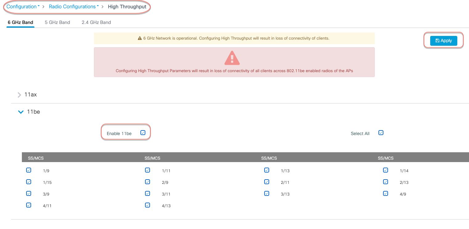
In the Cisco Wireless (Catalyst) 9800 controller GUI, navigate to Configurations > Radio Configurations > High Throughput, and choose Enable 11be for the bands where 802.11be is needed, and click Apply.
Note:
1. It is recommended to enable this for all the bands.
2. If 802.11be is enabled, MLO gets enabled too. This MLO setting is not independent and of the 802.11be configuration..
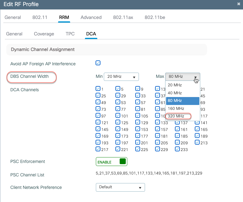
The channel width for the 6 GHz band, could be set to a maximum of 320 MHz in DBS channel width, for RRM to issue out a 320 MHz channel width, when its algorithm finds it conducive to issue a larger channel width.
From Configuration > Tags & Profiles > RF/Radio, edit the 6 GHz RF Profile to include 320 MHz as the max channel width.
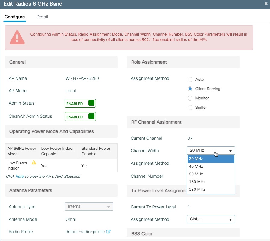
A specific AP could be statically configured for 320 MHz on the access point configuration page.
Navigate to Configuration > Wireless > Access Points > 6 GHz Radios, select the AP, change the RF channel assignment to Custom and select 320 MHz as the channel width.
Preamble puncturing is supported for 80 MHz or higher channel widths. For an 80 MHz, only 20 MHz is allowed to the punctured. The following table lists the allowed preamble puncturing options.
Table 7. Software Interoperability
| Channel Width |
Allowed Puncturing |
| 20 and 40 MHz |
Puncturing not allowed |
| 80 MHz |
20 MHz |
| 160 MHz |
20 or 40 MHz |
| 320 MHz |
40, 80 or 40 + 80 MHz |
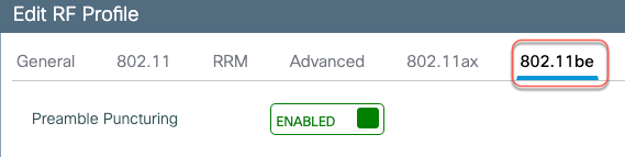
To enable Preamble Puncturing, navigate to Configuration > Tags & Profiles > RF/Radio > edit the RF Profile of the 5 GHz and 6 GHz bands and enable Preamble Puncturing under the 802.11be tab.
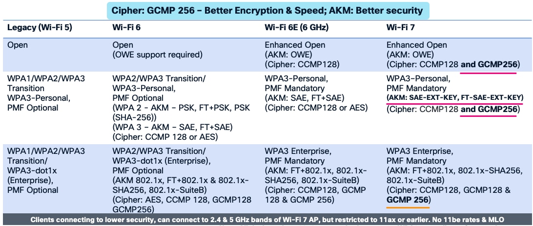
Wi-Fi 7 mandates the support for WPA3 and Enhanced Open (based on OWE) along with Protected Management Frame (PMF) for the clients to operate in 802.11be data rates and features like MLO. There are new AKMs (AKM 24 and 25) added for WPA3-Personal and GCMP-256 is mandatory as cipher for all Enhanced Open, WPA3-Personal and WPA3 Enterprise. Additionally, Wi-Fi 7 requires beacon protection for both the AP and the Wireless Clients. With MLO, security needs to be established across all the links of a multi-link association. The security requirements is to mainly make the Wi-Fi networks more secure and protect against cyberattacks.
The following table lists the security requirements for Wi-Fi 7 and comparison with previous Wi-Fi generations.
The security requirements for Wi-Fi 7 may necessitate a design change of the WLANs in the current deployment. There are a few options that the customer can consider, while implementing Wi-Fi 7.
Option 1 – Reconfigure the existing WLANs to WPA3/Enhanced Open, along with the required AKMs and Ciphers – i.e. one SSID for all radio policies. While this makes the WLAN most secure, there are practical difficulties in implementation, as many existing clients may not support WPA3 and PMF.
Option 2 – Add new SSIDs with the new security requirement for Wi-Fi 7 and have the newer clients associate to this SSID. This is an easy and flexible approach. The downside to this is maintaining additional SSIDs.
Option 3 – Migrate the SSIDs to Transition Mode –WPA3 Transition. This is a conservative approach, taking one step to make the WLANs more secure and allowing newer clients with WPA3 security and older clients with WPA2 security to co-exist.
Please refer to the C9800 WPA3 Deployment Guide for WLAN configuration details.
https://www.cisco.com/c/en/us/td/docs/wireless/controller/9800/technical-reference/wpa3-dg.html
Enable 11be in Meraki Mode
The first pre-requisite to make a WLAN to be 11be compatible is WLAN security confirmance. The security requirements listed in the security section have to be met to turn on 11be.
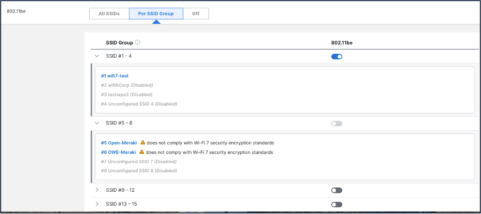
The Per SSID toggle for 802.11be (Wi-Fi 7) feature allows WiFi 7 access points to operate some SSIDs in 802.11ax mode while others operate in 802.11be mode. This is also called "ax/be mixed mode", "per-SSID 11be".
If the network has Wi-Fi 7 APs, then 802.11be has to be enabled per group. As stated earlier, all the SSIDs in a group of four has to be security compliant with Wi-Fi 7 requirements. The dashboard has four SSID groups.
Group 1 – SSID 1 to 4
Group 2 – SSID 5 to 8
Group 3 – SSID 9 to 12
Group 4 – SSID 13 to 15
Hence, the users are required to re-arrange the SSIDs that complies to the security within a group. As an example, all SSIDs that comply to Wi-Fi 7 requirement can be in Group 1, the SSIDs like WPA2 or Open that do not comply to Wi-Fi 7 can be in Group 2 and so on.
To enable 11be Per SSID Group,
1. Navigate to Wireless > Configuration > Radio Settings > RF Profiles
2. Edit the profile that is of interest.
3. Navigate to 802.11be section in the General Tab.
4. Toggle to Per SSID Group.
5. Ensure all SSIDs within a group are Wi-Fi 7 compliant and the 80.11be knob is enabled.
6. For 8011.be SSID groups that has non-compliant the SSIDs will be disabled.
Wi-Fi 7 Client Information
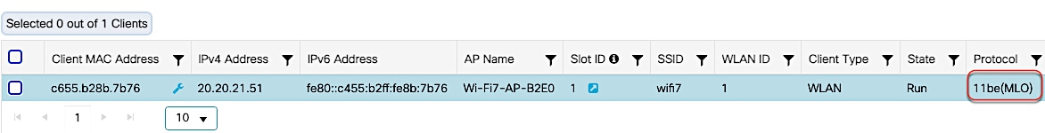
Viewing Wi-Fi 7 Clients in Cisco Wireless 9800 WLC
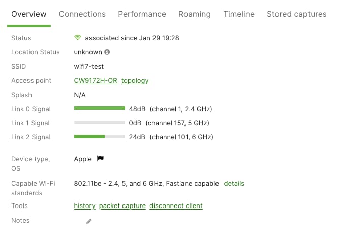
The Cisco Wireless (Catalyst) 9800 GUI displays the MLO capability and client statistics. From the main dashboard or Monitoring > Clients, select a client listed in the Protocol column as “11be (MLO)”.
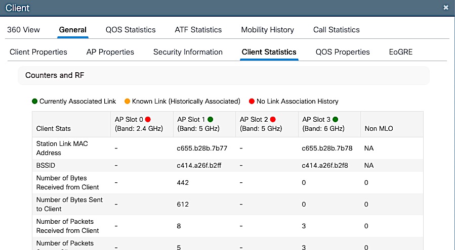
In the 360 View, the client’s MLO capability is indicated along with the number of radio slots it is associated to. In the example below, the client is associated to 2 radio slots.
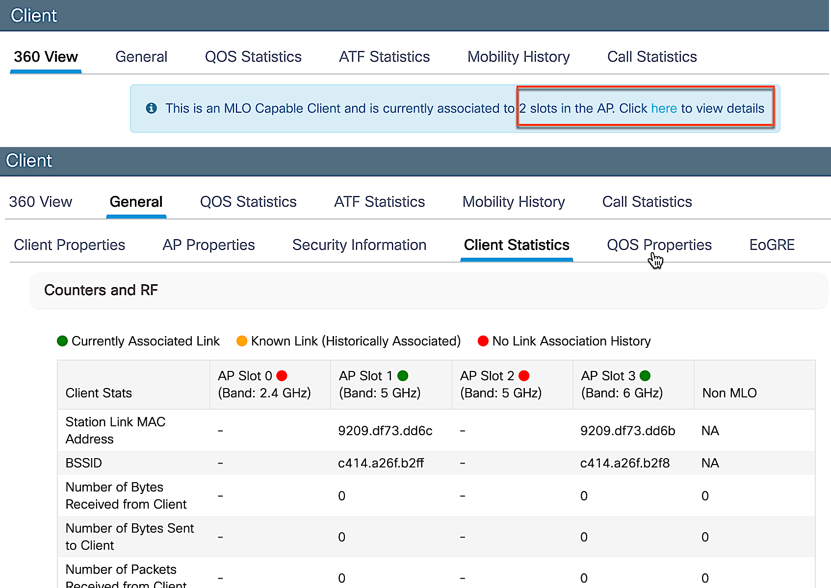
Click on the link to view the details, client propertis, security information and client statistics.
Viewing Wi-Fi 7 Clients in Meraki Dashboard
Meraki dashboard displays the MLO link information for the Wi-Fi 7 Client in the Client details page.
Migration between Management Modes
The Cisco Wireless CW9174x is a Global Use, Unified Product and can convert from the Cisco Catalyst management mode to the Meraki management mode and vice versa. This Unified Product gives you the flexibility of being deployed in a Catalyst 9800 WLC based deployment or cloud based Meraki deployment. It also provides investment protection for the future in case you want to switch between the two management options anytime from Day 1 to Day N.
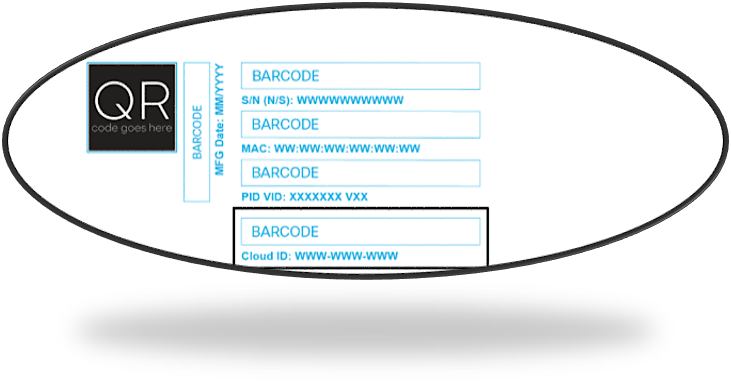
Starting with Wi-Fi 7 Access Points, the Meraki Serial Number has been renamed to “Cloud ID”. There is no functional change to how this was used in the previous generation product.
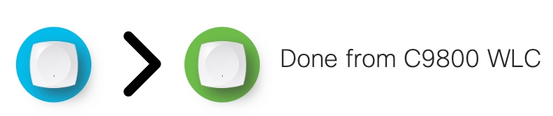
The CW9174x can be converted from Catalyst Management Mode to Meraki Management Mode through a simple work flow in C9800 WLC UI.
The following are the step to perform the conversion process.
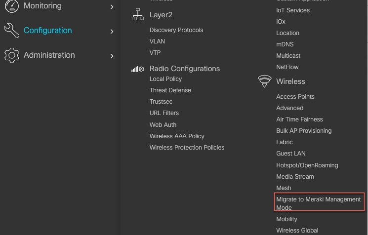
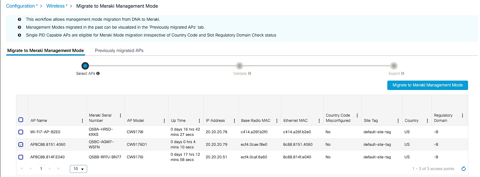
1. Start the conversion workflow from Configuration à Wireless à Migrate to Meraki Management Mode.
2. Select the APs you want to convert and click Migrate to Meraki Management Mode.
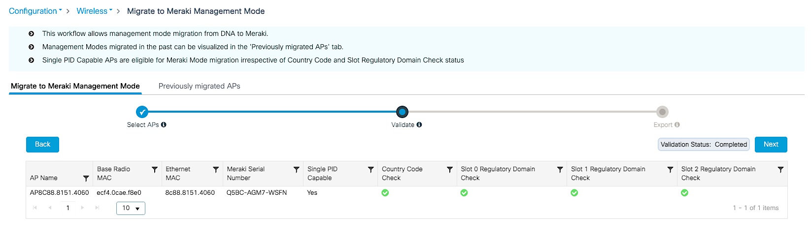
3. The controller will then validate the APs. Select Next.
4. Confirm the change on the selected Access Points.
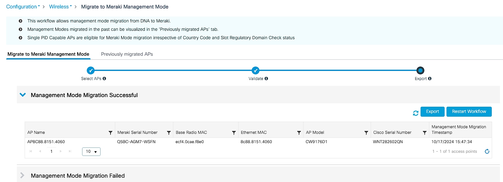
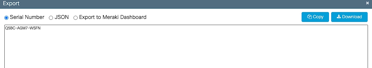
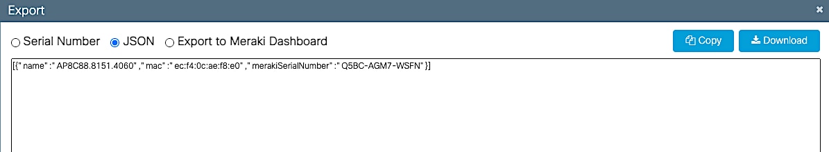
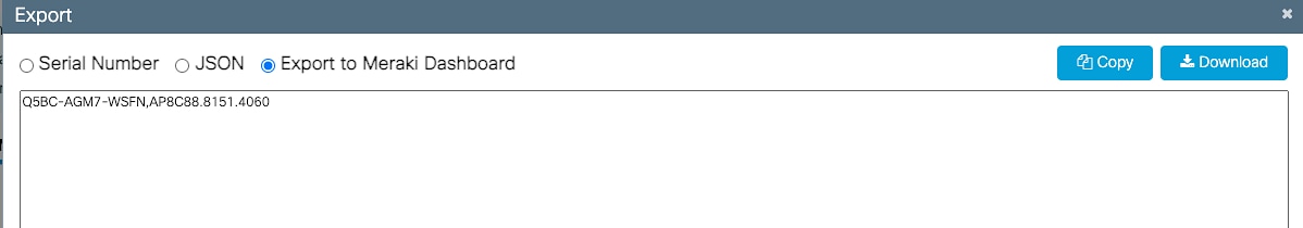
5. Export or download the data to be copied to Meraki Dashboard. The data can be exported in multiple formats – Serial Number, JSON or Export to Meraki Dashboard.
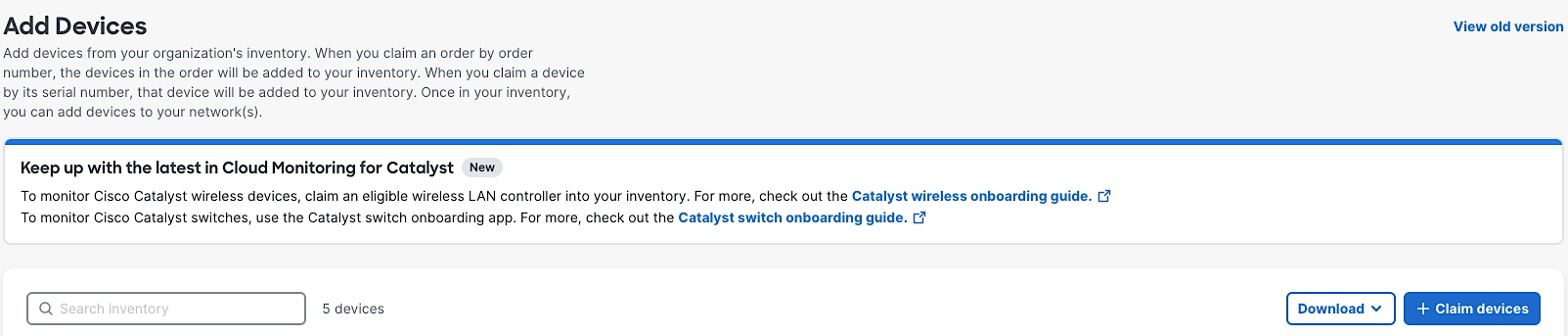
6. Add devices in Meraki Dashboard. Follow the Meraki Claim process.
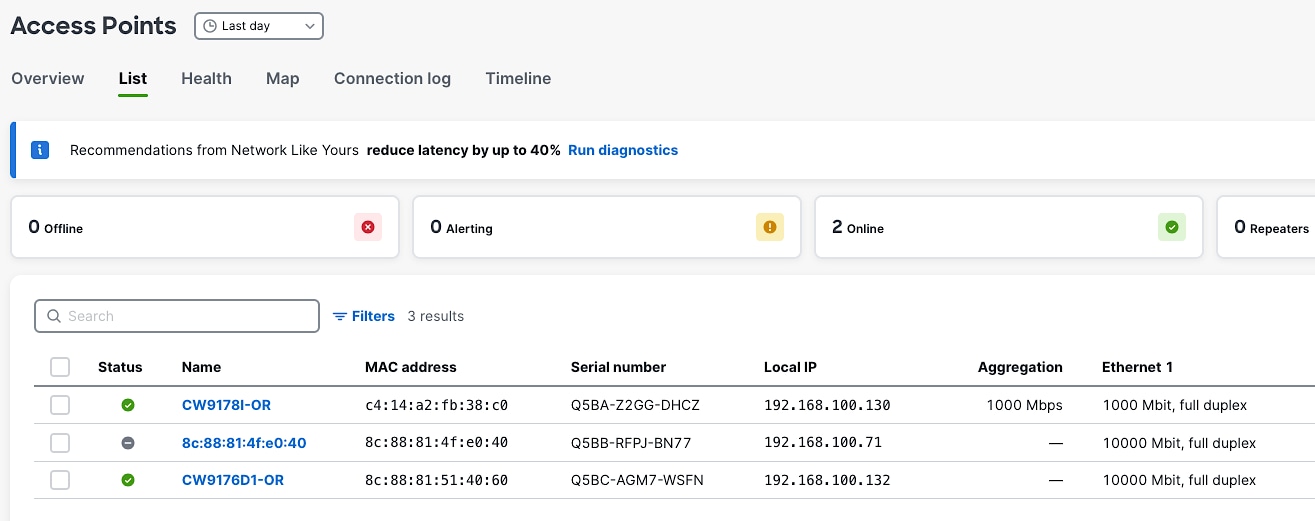
7. Once devices and claimed, the AP will appear in the dashboard in few minutes.
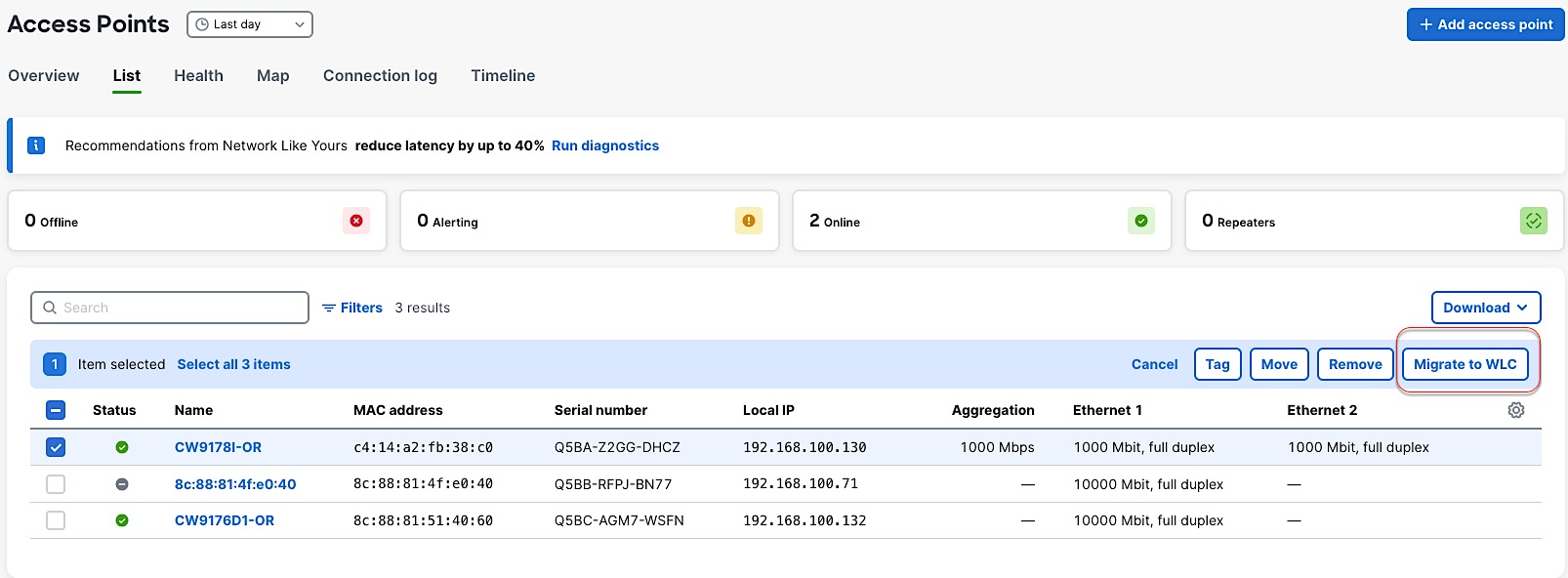
8. To convert an AP from Meraki Management Mode to Catalyst Management Mode, select the AP that you want to migrate and click on “Migrate to WLC”.
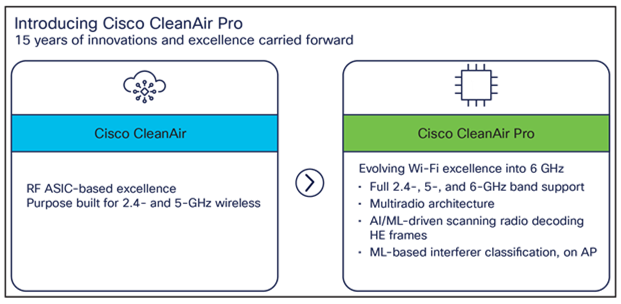
Wi-Fi 6E added 6 GHz spectrum for unlicensed use of Wi-Fi, and with it came new challenges for RF visibility and much more spectrum to monitor. In the past, the Catalyst 9100 APs relied on Cisco CleanAir® (software) and the RF-ASIC (hardware) for features such as packet capture, spectrum analysis, interference detection, and rogue and wireless intrusion prevention system (WIPS) detection. CleanAir and the RF-ASIC were great for RF visibility for the 2.4- and 5-GHz bands; however, with 6 GHz, Cisco CleanAir Pro and the AI/ML-driven scanning radio are being introduced to increase the performance and granularity required to manage this new spectrum (all 1200 MHz of it).
CleanAir Pro is software designed specifically for 6 GHz and the all-new challenges that have come with the introduction of 1200 MHz of spectrum. While many features work in conjunction with the AI/ML-driven scanning radio, CleanAir Pro also works with the Catalyst 9176x APs’ serving radios. Unlike previous generations of APs, CleanAir Pro can even decode extremely high throughput (EHT, 802.11be) frames, which is crucial since Wi-Fi 7 EHT frames. In the future, there will even be an ML-based interferer classification built directly into the AP software for more efficient interferer analysis, rather than loading the WLC or Cisco Catalyst Center.
The Cisco Wireless CW9174x supports Site Survey mode. The purpose of this mode is to allow users to conduct wireless site survey testing using a single access point, including understanding RF propagation, client join metrics, and so on, without the need for a controller. This mode converts the AP into a limited standalone mode, enabling it to broadcast 2.4-, 5-, and 6-GHz SSIDs and allowing wireless clients to join via an internal Dynamic Host Configuration Protocol (DHCP) pool. Site Survey mode provides all the control needed to configure and conduct a site survey. It lets users bring the AP into any environment with either a power source or battery backup and conduct a site survey test.
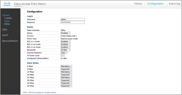
When the CW9174x is in Site Survey mode, you will be able to access the AP’s WebUI for each configuration and view various RF metrics for RF coverage and planning. These configurations include channel number, channel width, Tx power, SSID, and data rates.
The steps below describe how to convert a CW9174x AP into Site Survey mode:
1. Change the AP to Site Survey mode. Enter command “ap site-survey”
2. After booting up, the AP is automatically assigned a static IP of 10.0.23.1.
3. The AP will start broadcasting the C9178_site_survey SSID with open/OWE security.
4. Connect your wireless client with the C9178_site_survey SSID and it will receive an IP from 10.0.23.0/24.
5. Access the AP’s Site Survey WebUI via 10.0.23.1.
6. The first time, the default username and password are admin/admin. You will be directed to reset that insecure password on the first login.
7. When done, convert your AP back to CAPWAP mode to join the controller again. Enter command “ap capwap”
Note:
1. If an AP is converted to Site Survey mode while connected to a WLC, it will disjoin and go into standalone mode.
2. For the above mentioned Site Survey functionality, the AP should have joined a Catalyst 9800 WLC atleast once. When the AP is in Day 0 mode, the CLI to convert the AP to Site Survey mode is not present.
3. The AP carries over the country code configured, while it was connected to the Catalyst 9800 WLC.
References
1. CW9174E Hardware Install Guide
2. CW9174I Hardware Install Guide
4. C9800 WLC WPA3 Deployment Guide
5. Meraki WPA3 Deployment Guide
6. C9800 AFC Configuration Guide
7. GNSS Best Practices for AFC Deployment Guide
8. Meraki AFC Configuration Guide
Cisco and the Cisco logo are trademarks or registered trademarks of Cisco and/or its affiliates in the U.S. and other countries. To view a list of Cisco trademarks, go to this URL: www.cisco.com/go/trademarks. Third-party trademarks mentioned are the property of their respective owners. The use of the word partner does not imply a partnership relationship between Cisco and any other company. (1721R)
Any Internet Protocol (IP) addresses and phone numbers used in this document are not intended to be actual addresses and phone numbers. Any examples, command display output, network topology diagrams, and other figures included in the document are shown for illustrative purposes only. Any use of actual IP addresses or phone numbers in illustrative content is unintentional and coincidental.
© 2025 Cisco Systems, Inc. All rights reserved.