Introduction to the Reference Designs
 Note |
The first four chapters of this book are for anyone who wants to get familiar with the three contact center enterprise solutions:
|
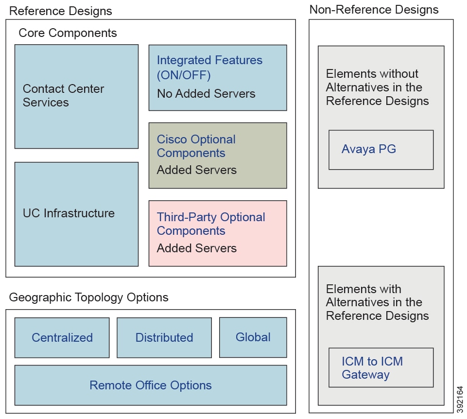
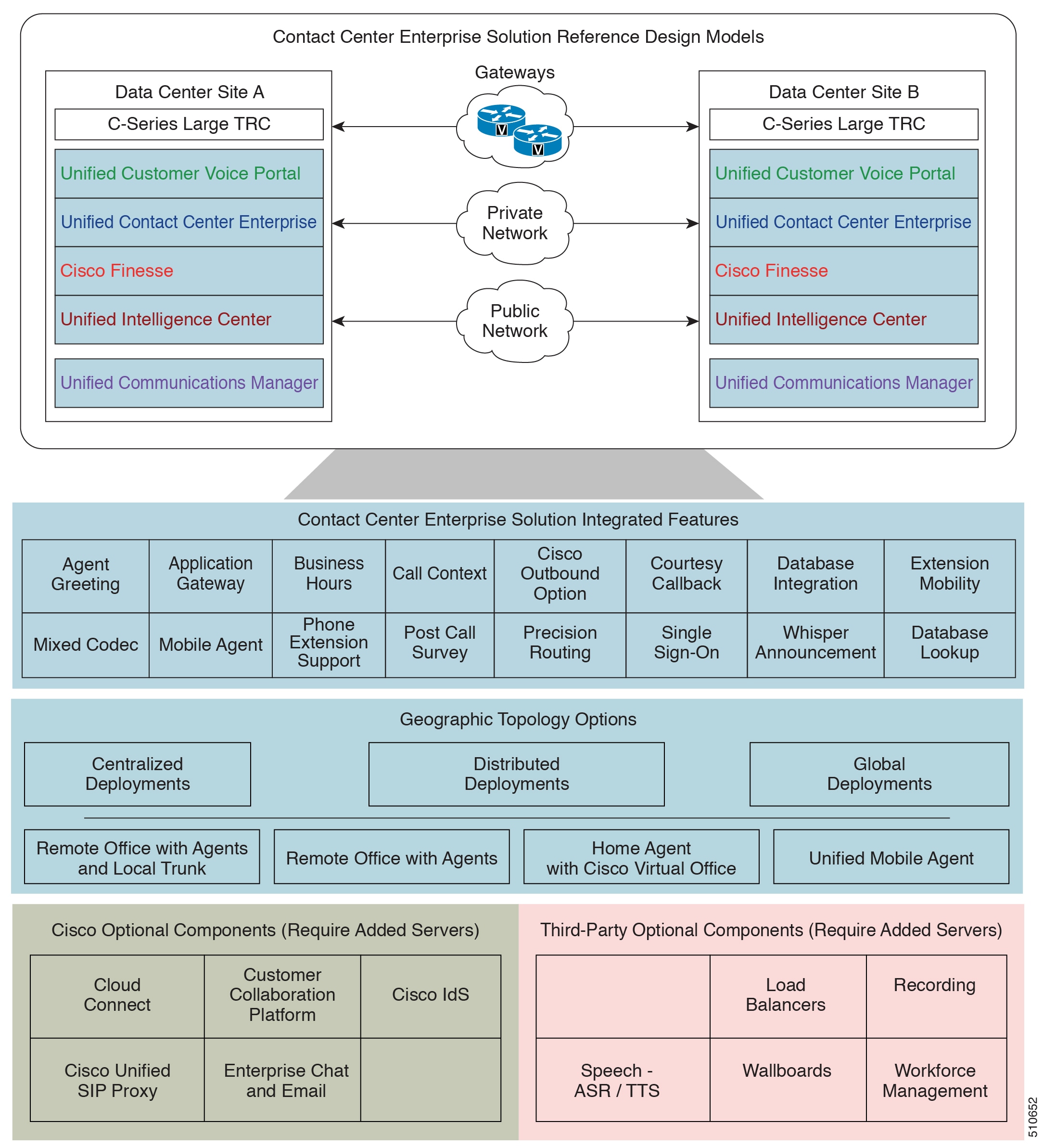
The Contact Center Enterprise Reference Designs are a set of Cisco validated designs of our contact center enterprise solutions. The Reference Designs define the technologies and topologies that fit the needs for most deployments. The Reference Designs focus on simplifying the contact center enterprise solution design. They provide complete contact center functionality based on components that are strategic to Cisco.
We have defined the Reference Designs in the following table to cover most contact center needs:
|
Reference Design |
Packaged CCE |
Cisco HCS for Contact Center |
Unified CCE |
|---|---|---|---|
|
2000 Agents |
Yes |
Yes |
Yes |
|
4000 Agents |
Yes |
Yes |
Yes |
|
12000 Agents |
Yes |
Yes |
Yes |
|
24000 Agents |
No |
Yes |
Yes |
|
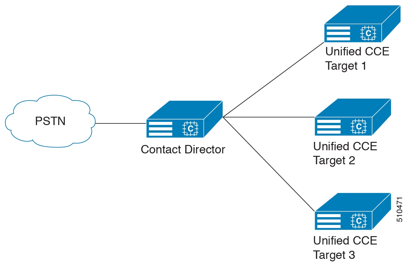
Contact Director |
No |
No |
Yes |
|
Non-Reference Designs |
Avaya PG and ICM-to-ICM Gateway |
Avaya PG only |
Yes |
If your solution exceeds the configuration limits for a particular Reference Design, use a Reference Design with higher limits. For example, if your 2000-agent deployment requires 350 active reporting users, use the 4000 Agent Reference Design for your solution.
Contact center solutions that include something not covered by the Contact Center Enterprise Reference Designs are called Non-Reference Designs. Cisco HCS for Contact Center supports the Avaya PG as a Non-Reference Design.
You require Unified CCE for any other Non-Reference Design deployments.
Reference Designs and Deployment Types
The Contact Center Enterprise Reference Designs are mapped to specific contact center solutions through deployment types. Deployment types are system codes that impose system limits and apply congestion control.
This table maps the Reference Designs and Non-Reference Designs with the deployment type that you use for each.
|
Reference Design |
Packaged CCE |
Cisco HCS for Contact Center |
Unified CCE |
|---|---|---|---|
|
Label |
Label |
Label |
|
|
2000 Agent |
Packaged CCE: 2000 Agents |
HCS-CC: 2000 Agents |
UCCE: 2000 Agents |
|
4000 Agent |
Packaged CCE: 4000 Agents |
HCS-CC: 4000 Agents |
UCCE: 4000 Agents |
|
12000 Agent |
Packaged CCE: 12000 Agents |
HCS-CC: 12000 Agents |
UCCE: 12000 Agents |
|
24000 Agent |
NA |
HCS-CC: 24000 Agents |
UCCE: 24000 Agents Router/Logger |
|
Contact Director |
NA |
NA |
Contact Director |
|
Non-Reference Designs |
Avaya PG and ICM-to-ICM Gateway Packaged CCE: 4000 Agents Packaged CCE: 12000 Agents |
NA |
ICM Rogger |
|
ICM Router/Logger |
|||
|
UCCE: 8000 Agents Router/Logger |
|||
|
Lab Only Designs |
Packaged CCE: Lab Mode |
NA |
UCCE: Progger (Lab Only) |
 Feedback