Maintaining the System
This chapter describes how to use LEDs to diagnose system problems and how to install or replace supported hardware components:
Status LEDs and Buttons
This section describes the location and meaning of LEDs and buttons and includes the following topics:
-
Internal Diagnostic LEDs• Internal Diagnostic LEDs, page 3-7
Front-Panel LEDs
Figure 3-1 shows the front-panel LEDs. Table 3-1 defines the front-panel LED states.
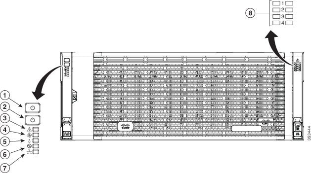
|
1 |
System Power button and power status LED |
5 |
Temperature status LED |
|
2 |
System unit identification button and LED |
6 |
Power supply status LED |
|
3 |
System status LED |
7 |
Network link activity LED |
|
4 |
Fan status LED |
8 |
Internal-drive status LEDs |
|
LED Name |
State |
|
|
1 |
System Power button/power status LED |
|
|
2 |
System unit identification |
|
|
3 |
System status |
|
|
4 |
Fan status |
|
|
5 |
Temperature status |
|
|
6 |
Power supply status |
|
|
7 |
Network link activity |
|
|
8 |
Internal-drive status LEDs |
Use these LEDs to indicate the location of a failing drive. Then open the system cover to find exactly which drive is failing
by looking at the LEDs on the drive trays.
|
Rear-Panel LEDs and Buttons
Figure 3-2 shows the rear-panel LEDs and buttons for a S3260 system. This example is shown with a C3X60 M4 server node and an optional four-drive expansion module. Table 3-2 defines the rear-panel LED states.
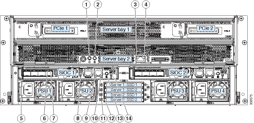
|
1 |
Server node Power button/LED (on each server node) |
8 |
Not used at this time. |
|
2 |
Server node unit identification button/LED (on each server node) |
9 |
10/100/1000 dedicated management port link activity LED (on each SIOC) |
|
3 |
1 Gb Ethernet port link speed LED (on each M5 server node only) |
10 |
10/100/1000 dedicated management port link speed LED (on each SIOC) |
|
4 |
1 Gb Ethernet port link activity LED (on each M5 server node only) |
11 |
Solid state drive activity LED (each drive bay) |
|
5 |
Power supply status LED (each power supply) |
12 |
Solid state drive fault LED (each drive bay) |
|
6 |
QSFP port link speed LED (on each port) Actual ports will vary, depending on which SIOC version is used, or which adapter card is installed in a Version 03 SIOC. |
13 |
Not used at this time. |
|
7 |
QSFP port link activity LED (on each port) |
14 |
SIOC health LED (one each Version 03 SIOC only) |
|
LED Name |
State |
|
|---|---|---|
|
1 |
Server node power button/LED |
|
|
2 |
Server node unit identification button/LED |
|
|
3 |
1 Gb Ethernet port link speed LED (on each M5 server node only) |
|
|
4 |
1 Gb Ethernet port link activity LED (on each M5 server node only) |
|
|
5 |
Power supply status (on each power supply unit) |
AC Power Supplies:
DC Power Supplies:
|
|
6 |
QSFP port link LED |
|
|
7 |
QSFP port activity LED |
|
|
8 |
Not used at this time. |
|
|
9 |
10/100/1000 dedicated management link activity |
|
|
10 |
10/100/1000 dedicated management link speed |
|
|
11 |
Solid state drive activity |
|
|
12 |
Solid state drive fault |
|
|
13 |
Not used at this time. |
|
|
14 |
SIOC health |
|
If your system has an optional drive expander module, it has one module status LED:
|
LED Status |
P3V3 |
P5V |
HDD Present |
HDD Status |
|---|---|---|---|---|
|
Off |
None |
None |
None |
None |
|
Green |
On |
On |
Plug-in |
Good |
|
Amber |
On |
On |
No plug-in |
NA |
|
Amber |
On |
Fail |
No plug-in |
NA |
|
Amber |
On |
On |
Plug-in |
Fail |
Internal Diagnostic LEDs
This section contains the following topics:
Diagnostic LEDs in the Main Chassis
The diagnostic LEDs inside the main chassis compartments can be viewed while the system is powered on. See Figure 3-3 for the locations of these internal LEDs. See Table 3-4 for definitions of the LED states.
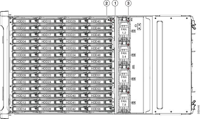
|
1 |
Drive fault (on each drive carrier) |
3 |
Fan module fault (on each fan module) |
|
2 |
Drive activity (on each drive carrier) |
|
LED Name |
State |
|
|---|---|---|
|
1 |
SAS drive fault |
|
|
2 |
SAS drive activity |
|
|
3 |
Fan fault LEDs |
|
Diagnostic LEDs in the Server Node
For the locations of the internal diagnostic LEDs inside the server node, see the service note for your server node:
Preparing for System Component Installation or Replacement
This section describes how to prepare for component installation, and it includes the following topics:
Required Equipment For Maintenance Procedures
The following equipment is used to perform the procedures in this chapter:
-
Number 1 Phillips-head screwdriver (for SIOC cover screws)
-
1/4-inch or equivalent flat-head screwdriver (for separating the optional I/O expander from the server node)
-
Electrostatic discharge (ESD) strap or other grounding equipment such as a grounded mat
-
The tools required for CPU replacement are supplied with a CPU spare.
Shutting Down and Powering Off the S3260 System
You can invoke a graceful shutdown or a hard shutdown of the entire S3260 system by using either the Cisco IMC interface or the system power button on the front panel.
 Caution |
To completely remove power from the system, you must disconnect power cords from all power supplies. |
You can also shut down an individual server node rather than the entire system. See Shutting Down an Individual Server Node.
To use the system power button to shut down the chassis, follow these steps:
SUMMARY STEPS
- Check the color of the System Power Status LED (see Front-Panel LEDs.
- Invoke either a graceful shutdown or a hard shutdown:
DETAILED STEPS
| Command or Action | Purpose | |||
|---|---|---|---|---|
|
Step 1 |
Check the color of the System Power Status LED (see Front-Panel LEDs. |
|
||
|
Step 2 |
Invoke either a graceful shutdown or a hard shutdown: |
|
||
|
Step 3 |
|
Disconnect power cords from all power supplies in your system to completely remove AC power and power off the system chassis. |
Shutting Down an Individual Server Node
You can invoke a graceful shutdown or a hard shutdown of a server node by using either the Cisco Integrated Management Controller (Cisco IMC) interface, or the power button that is on the face of the server node.
Shutting Down a Server Node By Using the Cisco IMC GUI
To use the Cisco IMC GUI to shut down the server node, follow these steps:
SUMMARY STEPS
- Use a browser and the management IP address of the system to log in to the Cisco IMC GUI.
- In the Navigation pane, click the Chassis menu.
- In the Chassis menu, click Summary.
- In the toolbar above the work pane, click the Host Power link.
- In the Server Power Management dialog, select one of the following buttons for the server that you want to shut down:
DETAILED STEPS
| Command or Action | Purpose | |||
|---|---|---|---|---|
|
Step 1 |
Use a browser and the management IP address of the system to log in to the Cisco IMC GUI. |
|||
|
Step 2 |
In the Navigation pane, click the Chassis menu. |
|||
|
Step 3 |
In the Chassis menu, click Summary. |
|||
|
Step 4 |
In the toolbar above the work pane, click the Host Power link. |
The Server Power Management dialog opens. This dialog lists all servers that are present in the system. |
||
|
Step 5 |
In the Server Power Management dialog, select one of the following buttons for the server that you want to shut down: |
It is safe to remove the server node from the chassis when the Chassis Status pane shows the Power State as Off for the server node that you are removing. The physical power button on the server node face also turns amber when it is safe to remove the server node from the chassis. |
Shutting Down a Server Node By Using the Power Button on the Server Node
To use the physical server node power button to shut down the server node only, follow these steps:
SUMMARY STEPS
- Check the color of the server node power status LED:
- Invoke either a graceful shutdown or a hard shutdown:
DETAILED STEPS
| Command or Action | Purpose | |||
|---|---|---|---|---|
|
Step 1 |
Check the color of the server node power status LED: |
|
||
|
Step 2 |
Invoke either a graceful shutdown or a hard shutdown: |
When the server node power button turns amber, it is safe to remove the server node from the chassis. |
Removing Chassis and Component Covers
This section contains the following topics:
Opening the Main Chassis Top Covers
This system has three hinged top covers on the main chassis. Opening these covers gives access to the internal-drives compartment and the fan module compartment.
 Note |
The internal drives and cooling fans in the system are hot-swappable and are accessed by opening the top covers. When you rack and cable the system, be sure to allow enough slack in the power and other cables so that the system can be pulled out on the slide rails far enough to allow clearance for opening the top covers. |
SUMMARY STEPS
- Open the left or right internal-drive compartment cover to access the hot-swappable internal drives:
- Open the fan compartment cover to access the hot-swappable fan modules:
DETAILED STEPS
| Command or Action | Purpose | |||||||||
|---|---|---|---|---|---|---|---|---|---|---|
|
Step 1 |
Open the left or right internal-drive compartment cover to access the hot-swappable internal drives: |
|
||||||||
|
Step 2 |
Open the fan compartment cover to access the hot-swappable fan modules: |
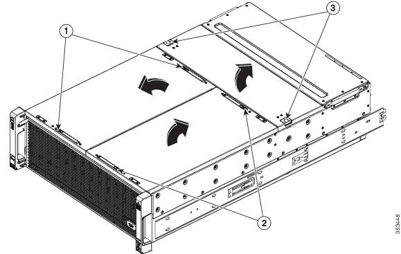
|
Removing a Server Node Cover
-
To remove a server node cover, see the service note for your server node:
Cisco UCS C3X60 M3 Server Node For Cisco UCS S3260 System Service Note
-
Cisco UCS C3X60 M4 Server Node For Cisco UCS S3260 System Service Note
-
Cisco UCS S3260 M5 Server Node For Cisco UCS S3260 System Service Note
Removing an I/O Expander Cover (C3X60 M4 and S3260 M5 Server Nodes Only)
To remove an I/O expander cover, see the C3X60 M4 server node service note:
Removing an I/O Expander From a Node (C3X60 M4 and S3260 M5 Server Nodes Only)
The I/O expander attaches to the top of the server node. To remove an I/O expander from a server node
so that you can access the components inside the server node, see the server node service note:
Removing the System I/O Controller (SIOC) Cover
Note |
You do not have to slide the system out of the rack to remove the SIOC from the rear of the system. |
SUMMARY STEPS
- Power off the connected server nodes based on the scenario:
- Remove the SIOC from the system:
- Remove the SIOC cover:
- Reinstall the SIOC cover:
- Reinstall the SIOC in the system:
- Power on the server node that you powered off in the first step.
DETAILED STEPS
| Command or Action | Purpose | |||||||||||||
|---|---|---|---|---|---|---|---|---|---|---|---|---|---|---|
|
Step 1 |
Power off the connected server nodes based on the scenario: |
|
||||||||||||
|
Step 2 |
Remove the SIOC from the system: |
|
||||||||||||
|
Step 3 |
Remove the SIOC cover: |
|
||||||||||||
|
Step 4 |
Reinstall the SIOC cover: |
|
||||||||||||
|
Step 5 |
Reinstall the SIOC in the system: |
|
||||||||||||
|
Step 6 |
Power on the server node that you powered off in the first step. |
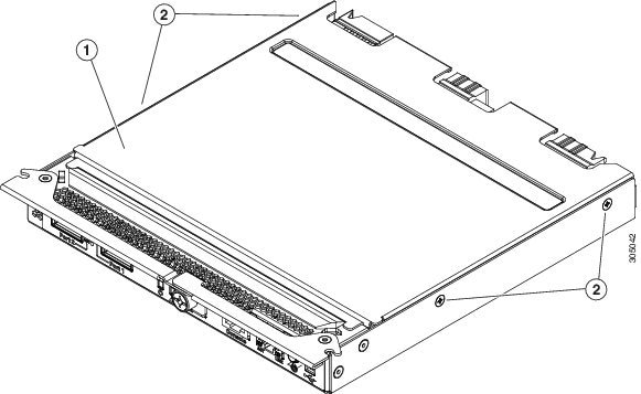
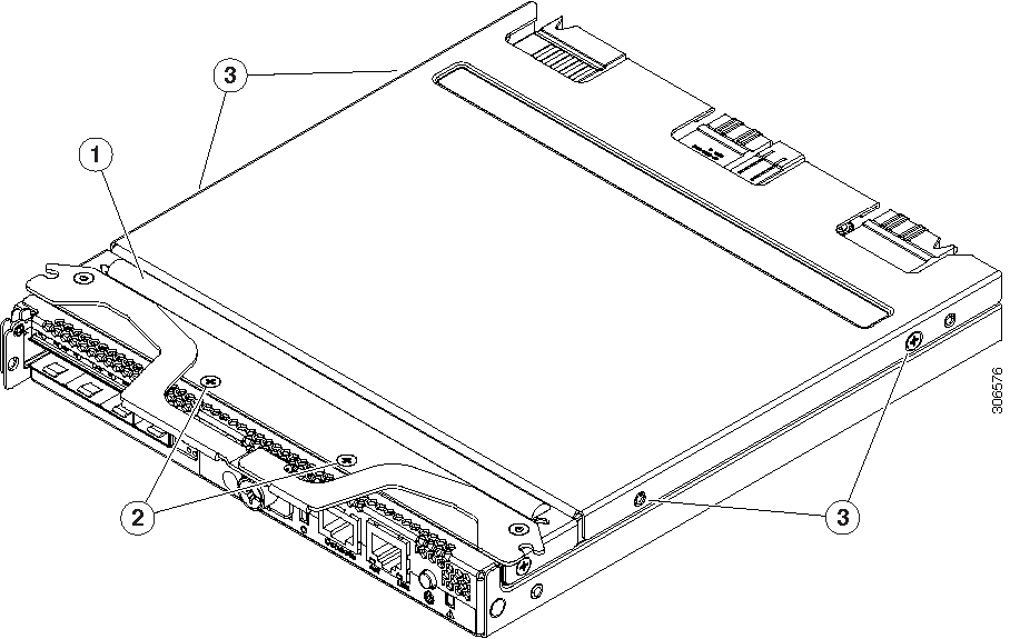
|
Installing or Replacing System Components
 Warning |
Blank faceplates and cover panels serve three important functions: they prevent exposure to hazardous voltages and currents inside the chassis; they contain electromagnetic interference (EMI) that might disrupt other equipment; and they direct the flow of cooling air through the chassis. Do not operate the system unless all cards, faceplates, front covers, and rear covers are in place. Statement 1029 |
Caution |
This system weighs approximately 190 pounds (86 kilograms) when fully loaded with components. We recommend that you use a mechanical lift when lifting the system. Attempting this procedure alone could result in personal injury or equipment damage. Consider temporarily removing components such as hard drives while you move the system. |
-
Replacing an SSD Inside the Server Node (C3X60 M4 or S3260 M5 Only)
-
Replacing an Internal USB Drive Inside the Server Node (C3X60 M3 Only)
-
Installing a Trusted Platform Module (TPM) Inside the Server Node
-
Replacing an I/O Expander (C3X60 M4 or S3260 M5 Server Nodes Only)
-
Replacing a PCIe Card Inside the I/O Expander (C3X60 M4 or S3260 M5 Server Nodes Only)
-
Replacing a Storage Controller Card Inside the I/O Expander (C3X60 M4 Server Nodes Only)
-
Replacing an NVMe SSD Inside the I/O Expander (C3X60 M4 or S3260 M5 Server Nodes Only)
- Replacing an RTC Battery Inside the S3260 SIOC
-
Replacing a PCIe Adapter Card Inside the S3260 SIOC (Version 03 SIOC Only)
-
Replacing an NVMe SSD Inside the S3260 SIOC (Version 03 SIOC Only)
Replacing Hard Drives or Solid State Drives
This section includes the following topics:
4K Sector Format Drives Considerations
-
• You must boot 4K sector format drives in UEFI mode, not legacy mode. See Setting Up Booting in UEFI Mode in the BIOS Setup Utility, or Setting Up Booting in UEFI Mode in the Cisco IMC GUI.
-
• Do not configure 4K sector format and 512-byte sector format drives as part of the same RAID volume.
-
• Operating system support on 4K sector drives is as follows: Windows: Win2012 and Win2012R2; Linux: RHEL 6.5, 6.6, 6.7, 7.0, 7.2; SLES 11 SP3, and SLES 12. ESXi/Vmware is not supported.
-
• The 6 TB drives have 4096-byte sectors. VMware ESXi does not support this capability and therefore will not work with 6 TB drives.
Setting Up Booting in UEFI Mode in the BIOS Setup Utility
SUMMARY STEPS
- Use a web browser and the management IP address of the system to log into the Cisco IMC GUI management interface.
- Select Compute and then Server 1.
- Click Launch KVM to open a virtual KVM window for the server node.
- In the Launch KVM dialog, select Server 1 and click Launch.
- Reboot server node 1. Watch the KVM window for the prompt to press F2.
- Enter the BIOS setup utility by pressing the F2 key when prompted during bootup.
- Go to the Boot Options tab.
- Set UEFI Boot Options to Enabled.
- Under Boot Option Priorities, set your OS installation media (such as a virtual DVD) as your Boot Option #1.
- Go to the Advanced tab.
- Select LOM and PCIe Slot Configuration.
- Set the PCIe Slot ID: HBA Option ROM to UEFI Only.
- Press F10 to save changes and exit the BIOS setup utility. Allow the server to reboot.
- After the server reboots and the OS installs, verify the installation:
DETAILED STEPS
| Command or Action | Purpose | |
|---|---|---|
|
Step 1 |
Use a web browser and the management IP address of the system to log into the Cisco IMC GUI management interface. |
|
|
Step 2 |
Select Compute and then Server 1. |
|
|
Step 3 |
Click Launch KVM to open a virtual KVM window for the server node. |
|
|
Step 4 |
In the Launch KVM dialog, select Server 1 and click Launch. |
|
|
Step 5 |
Reboot server node 1. Watch the KVM window for the prompt to press F2. |
|
|
Step 6 |
Enter the BIOS setup utility by pressing the F2 key when prompted during bootup. |
|
|
Step 7 |
Go to the Boot Options tab. |
|
|
Step 8 |
Set UEFI Boot Options to Enabled. |
|
|
Step 9 |
Under Boot Option Priorities, set your OS installation media (such as a virtual DVD) as your Boot Option #1. |
|
|
Step 10 |
Go to the Advanced tab. |
|
|
Step 11 |
Select LOM and PCIe Slot Configuration. |
|
|
Step 12 |
Set the PCIe Slot ID: HBA Option ROM to UEFI Only. |
|
|
Step 13 |
Press F10 to save changes and exit the BIOS setup utility. Allow the server to reboot. |
|
|
Step 14 |
After the server reboots and the OS installs, verify the installation: |
Setting Up Booting in UEFI Mode in the Cisco IMC GUI
SUMMARY STEPS
- Use a web browser and the management IP address of the system to log into the Cisco IMC GUI management interface.
- Select Compute and then Server 1.
- Select the BIOS tab.
- Under BIOS Properties, set Configured Boot Order to UEFI.
- Click Save Changes.
- Click Configure Boot Order.
- Select the Advanced tab.
- Click Add Local HDD.
- In the Add Local Disk dialog, enter the information for the 4K sector format drive. Enter a name and specify Slot M.
- Click Save Changes.
- Click Add Virtual Media.
- In the Add Virtual Media dialog, enter a name for your OS installation virtual media.
- Click Save Changes.
- Click Close.
- Click Launch KVM to open a virtual KVM window for the server node.
- In the Launch KVM dialog, select Server 1 and click Launch.
- Activate virtual media. Pull down the Virtual Media menu on the KVM window and select Activate Virtual Devices.
- Reboot the server node.
- Press F6 during the boot to enter the boot device menu.
- Select UEFI: Cisco vKVM-Mapped vDVD and press Enter.
- Proceed with the installation of your OS.
DETAILED STEPS
| Command or Action | Purpose | |
|---|---|---|
|
Step 1 |
Use a web browser and the management IP address of the system to log into the Cisco IMC GUI management interface. |
|
|
Step 2 |
Select Compute and then Server 1. |
|
|
Step 3 |
Select the BIOS tab. |
|
|
Step 4 |
Under BIOS Properties, set Configured Boot Order to UEFI. |
|
|
Step 5 |
Click Save Changes. |
|
|
Step 6 |
Click Configure Boot Order. |
|
|
Step 7 |
Select the Advanced tab. |
|
|
Step 8 |
Click Add Local HDD. |
|
|
Step 9 |
In the Add Local Disk dialog, enter the information for the 4K sector format drive. Enter a name and specify Slot M. |
|
|
Step 10 |
Click Save Changes. |
|
|
Step 11 |
Click Add Virtual Media. |
|
|
Step 12 |
In the Add Virtual Media dialog, enter a name for your OS installation virtual media. |
|
|
Step 13 |
Click Save Changes. |
|
|
Step 14 |
Click Close. |
|
|
Step 15 |
Click Launch KVM to open a virtual KVM window for the server node. |
|
|
Step 16 |
In the Launch KVM dialog, select Server 1 and click Launch. |
|
|
Step 17 |
Activate virtual media. Pull down the Virtual Media menu on the KVM window and select Activate Virtual Devices. |
|
|
Step 18 |
Reboot the server node. |
|
|
Step 19 |
Press F6 during the boot to enter the boot device menu. |
|
|
Step 20 |
Select UEFI: Cisco vKVM-Mapped vDVD and press Enter. |
|
|
Step 21 |
Proceed with the installation of your OS. |
After the OS installs and the system reboots, your OS is listed as a boot option. |
Replacing HDDs or SSDs in the Internal Drive Compartment
This section contains the following topics:
Internal Drive Population Guidelines
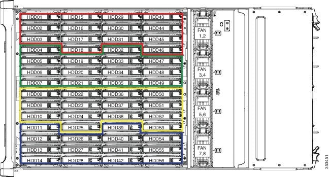
The system has 56 internal drive bays in the main chassis. Figure 3-7 shows the internal drive bay numbering. When populating internal drives and for optimal results please adhere to the following guidelines:
-
Populate HDDs starting from the lowest-numbered bays to the highest. Populate row 1 – 14, then row 15 – 28, and so on.
-
Populate internal SSDs starting from the highest-numbered bays to the lowest. Populate bay 56, then bay 55, and so on.
For example, a system with 36 HDDs and 2 SSDs should have the HDDs in bays 1 – 36 and the SSDs in bays 56 and 55.
-
The four colored boxes shown in Figure 3-7 represent the four power groups in which power is distributed to the drive bays.
Identifying a Faulty Internal Drive
The system has internal-drive fault LEDs on the right-front handle (see Figure 3-1). Use these LEDs to get an indication of the location of a failing drive.
SUMMARY STEPS
- Observe the internal-drive fault LEDs on the right-front handle.
- Open the right- or left-side cover and look at the fault LEDs on the drive trays.
DETAILED STEPS
| Command or Action | Purpose | |||||||||
|---|---|---|---|---|---|---|---|---|---|---|
|
Step 1 |
Observe the internal-drive fault LEDs on the right-front handle. |
See Figure 3-8 for an example. In this example, the amber LED indicates that the failing drive is in the right half of the internal drive compartment, in row 3. |
||||||||
|
Step 2 |
Open the right- or left-side cover and look at the fault LEDs on the drive trays. |
A solid amber fault LED indicates a failed drive. 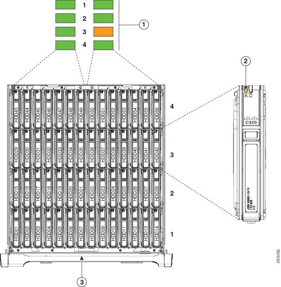
|
Replacing Internal Drives
Note |
Cisco PID UCSC-C3X60-HD4TB (Toshiba model MG03SCA400) has been EOLed and should be replaced if any problems occur. This Cisco PID now uses a newer HGST model. |
Note |
SAS HDDs and SSDs are hot-swappable and can be replaced without removing power from the system. |
SUMMARY STEPS
- Slide the system out the front of the rack far enough so that you can open the top cover.
- Identify a failing drive as described in Identifying a Faulty Internal Drive.
- Open the internal-drive compartment cover.
- Remove the faulty drive:
- Install a new drive:
- Close the chassis cover and push the system back into the rack.
DETAILED STEPS
| Command or Action | Purpose | |||||||||
|---|---|---|---|---|---|---|---|---|---|---|
|
Step 1 |
Slide the system out the front of the rack far enough so that you can open the top cover. |
|
||||||||
|
Step 2 |
Identify a failing drive as described in Identifying a Faulty Internal Drive. |
|||||||||
|
Step 3 |
Open the internal-drive compartment cover. |
|||||||||
|
Step 4 |
Remove the faulty drive: |
|
||||||||
|
Step 5 |
Install a new drive: |
|
||||||||
|
Step 6 |
Close the chassis cover and push the system back into the rack. |
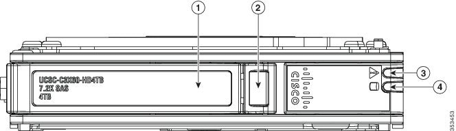
|
Replacing Hard Drives in the Optional Disk Expansion Tray
This section contains the following topics:
Disk Expansion Tray Drives Population Guidelines
The optional disk expansion tray can hold up to four 3.5-inch hard drives,. Drive numbering is shown in Figure 3-10. When populating these drives, follow these guidelines.
-
Populate drives starting from the lowest-numbered bay to the highest.
Figure 10. Figure 3-10 Disk Expansion Tray and Solid State Drive Numbering 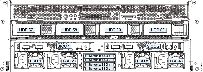
Identifying a Faulty Disk Expansion Tray Drive
Each drive has a fault LED that lights solid amber to indicate a failing drive.
Replacing Drive Expander Module Drives
Note |
SAS/SATA drives are hot-swappable and can be replaced without removing power from the system. |
SUMMARY STEPS
- Identify a failing drive as described in Identifying a Faulty Disk Expansion Tray Drive.
- Remove the faulty drive:
- Install a new drive:
DETAILED STEPS
| Command or Action | Purpose | |||||||||
|---|---|---|---|---|---|---|---|---|---|---|
|
Step 1 |
Identify a failing drive as described in Identifying a Faulty Disk Expansion Tray Drive. |
|||||||||
|
Step 2 |
Remove the faulty drive: |
|
||||||||
|
Step 3 |
Install a new drive: |
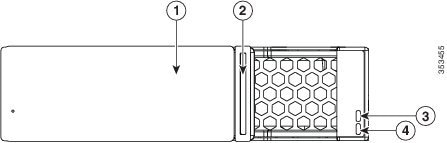
|
Replacing SAS/SATA Solid State Drives in the Rear Panel Bays
This section contains the following topics:
Rear-Panel SAS/SATA Solid State Drive Population Guidelines
There are four bays for SAS/SATA SSDs in the rear panel. Drive numbering is shown in Figure 3-12. When populating these drives, follow these guidelines.
-
Server 1 SSD1 and SSD2 can be managed by server node 1. See also Management Architecture.
-
Server 2 SSD1 and SSD1 can be managed by server node 2.
-
Populate drives starting with the lowest-numbered bay to the highest within each server-controlled pair.
-
If a pair of SSDs is not present, keep the blanking panel in the empty two SSD bays to ensure proper air flow (see Figure 3-12).
Identifying a Faulty Solid State Drive
Each solid state drive bay has a fault LED that lights solid amber to indicate a failing drive (see Rear-Panel LEDs and Buttons.
Replacing Solid State Drives
Note |
SAS/SATA solid state drives are hot-swappable and can be replaced without removing power from the system. |
SUMMARY STEPS
- Remove a faulty solid state drive:
- Install a new solid state drive:
DETAILED STEPS
| Command or Action | Purpose | |||||||||||
|---|---|---|---|---|---|---|---|---|---|---|---|---|
|
Step 1 |
Remove a faulty solid state drive: |
|
||||||||||
|
Step 2 |
Install a new solid state drive: |
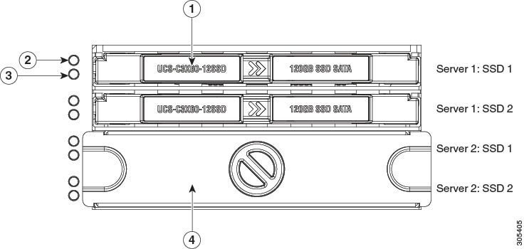
|
Replacing Fan Modules
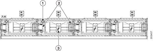
Each fan module contains two fans. See Figure 3-13 for the fan numbering.
You do not have to shut down or power off the system to replace fan modules because they are hot-swappable. Do not operate the system with a fan module removed for more than one minute.
 Tip |
Each fan module has a fault LED that lights amber if the fan module fails. |
SUMMARY STEPS
- Slide the system out the front of the rack far enough so that you can open the fan compartment cover.
- Open the fan compartment cover as described in Opening the Main Chassis Top Covers.
- Remove the fan module:
- Install a new fan module:
- Close the fan compartment cover and then push the system back into the rack.
DETAILED STEPS
| Command or Action | Purpose | |||||||||
|---|---|---|---|---|---|---|---|---|---|---|
|
Step 1 |
Slide the system out the front of the rack far enough so that you can open the fan compartment cover. |
|
||||||||
|
Step 2 |
Open the fan compartment cover as described in Opening the Main Chassis Top Covers. |
|||||||||
|
Step 3 |
Remove the fan module: |
|
||||||||
|
Step 4 |
Install a new fan module: |
|
||||||||
|
Step 5 |
Close the fan compartment cover and then push the system back into the rack. |
|
Replacing a Server Node
The system can support one or two server nodes.
-
• Cisco IMC releases earlier than 2.0(13): If your S3260 system has only one server node, it must be installed in bay 1.
-
• Cisco IMC releases 2.0(13) and later: If your S3260 system has only one server node, it can be installed in either server bay.
Note |
Whichever bay a server node is installed to, it must have a corresponding SIOC. That is, a server node in bay 1 must be paired with a SIOC in SIOC slot 1; a server node in bay 2 must be paired with a SIOC in SIOC bay 2. See Overview of Cisco UCS S3260 ArchitectureOverview of Cisco UCS S3260 Architecture, for more information. |
To replace a server node, including exporting and importing its configuration, see the service note for your server node:
Replacing a Disk Expansion Tray
The system can support one optional disk expansion tray, in server bay 2 only.
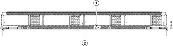
Tip |
The tray contains one status LED (see Figure 3-14 for the location and Table 3-3 for definitions of the LED states). |
|
1 |
Disk expansion tray status LED |
2 |
Disk expansion tray ejector levers (two) |
Note |
The disk expansion tray is hot-swappable, which means that you can remove it without shutting down system power. |
The disk expansion tray is accessed from the rear of the system, so you do not have to pull the system out from the rack.
SUMMARY STEPS
- Remove a disk expansion tray from the system:
- Remove any drives from the old tray and move them to your new disk expansion tray. Install each drive to the same position that it occupied in the old tray.
DETAILED STEPS
| Command or Action | Purpose | |
|---|---|---|
|
Step 1 |
Remove a disk expansion tray from the system: |
|
|
Step 2 |
Remove any drives from the old tray and move them to your new disk expansion tray. Install each drive to the same position that it occupied in the old tray. |
|
|
Step 3 |
|
Install a new disk expansion tray (server bay 2 only):
|
Replacing a System I/O Controller (SIOC)
The system can support up to two system I/O controllers (SIOCs).
For information about the management architecture and the chassis management controller (CMC) that is in each SIOC, see Management Architecture.
This section contains the following topics:
Note |
If you are replacing a Version 02 SIOC (UCSC-S3260-SIOC) with a Version 03 SIOC (UCS-S3260-PCISIOC), use the procedure in Migrating From Migrating From Version 02 SIOC to Version 03 SIOC. Version 03 SIOCs require Cisco IMC 4.0(1n) or later and for UCS Manager-controlled systems, Cisco UCS Manager 4.0(1n) or later. |
Note |
The Version 03 SIOC is supported only with S3260 M5 or later server nodes. |
Note |
The Version 03 SIOC is supported only with S3260 M5 or later server nodes. |
Note |
The Version 03 SIOC is supported only with S3260 M5 or later server nodes. |
Note |
If you move a SIOC from one chassis to another, the SIOC’s CMC configuration is treated as incompatible and is automatically deleted. The CMC will sync with the active CMC configuration. |
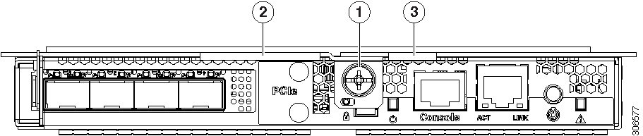
|
1 |
Lever thumbscrew |
3 |
Right ejector lever. |
|
2 |
Left ejector lever. |
Replacing a SIOC in a Single-SIOC System
You do not have to slide the system out of the rack to remove the SIOC from the rear of the system. The SIOC can be replaced without powering off the chassis.
SUMMARY STEPS
- Export the CMC configuration from the SIOC.
- Export the adapter configuration from the SIOC.
- Power off the connected server nodes based on the scenario:
- Remove the SIOC from the system:
- Version 03 SIOC Only: If desired, transfer the adapter card and any NVMe SSDs from the existing Version 03 SIOC to the new Version 03 SIOC:
- Install the new SIOC:
- Wait for the CMC in the new SIOC to finish booting.
- Import the CMC configuration that you exported earlier to the new SIOC’s CMC.
- Import the adapter configuration that you exported earlier to the new SIOC’s CMC.
- Power on the server node that you powered off earlier.
- Update the SIOC firmware using the Host Upgrade Utility. This will ensure that the firmware version on the SIOC is compatible with the latest system firmware.
DETAILED STEPS
| Command or Action | Purpose | |||
|---|---|---|---|---|
|
Step 1 |
Export the CMC configuration from the SIOC. |
|||
|
Step 2 |
Export the adapter configuration from the SIOC. |
|||
|
Step 3 |
Power off the connected server nodes based on the scenario: |
|
||
|
Step 4 |
Remove the SIOC from the system: |
|
||
|
Step 5 |
Version 03 SIOC Only: If desired, transfer the adapter card and any NVMe SSDs from the existing Version 03 SIOC to the new Version 03 SIOC: |
|
||
|
Step 6 |
Install the new SIOC: |
|
||
|
Step 7 |
Wait for the CMC in the new SIOC to finish booting. |
|||
|
Step 8 |
Import the CMC configuration that you exported earlier to the new SIOC’s CMC. |
|||
|
Step 9 |
Import the adapter configuration that you exported earlier to the new SIOC’s CMC. |
|||
|
Step 10 |
Power on the server node that you powered off earlier. |
|||
|
Step 11 |
Update the SIOC firmware using the Host Upgrade Utility. This will ensure that the firmware version on the SIOC is compatible with the latest system firmware. |
|
Replacing a SIOC in a Dual-SIOC System
You do not have to slide the system out of the rack to remove the SIOC from the rear of the system. The SIOC can be replaced without powering off the chassis.
SUMMARY STEPS
- Set the CMC in the SIOC as the standby CMC, if it is not already.
- Export the adapter configuration from the SIOC.
- Power off the connected server nodes based on the scenario:
- Remove the SIOC from the system:
- Version 03 SIOC Only: If desired, transfer the adapter card and any NVMe SSDs from the existing Version 03 SIOC to the new Version 03 SIOC:
- Install the new SIOC:
- Wait for the CMC in the new SIOC to finish booting.
- Power on the server node that you powered off earlier.
- Update the SIOC firmware using the Host Upgrade Utility. This will ensure that the firmware version on the SIOC is compatible with the latest system firmware.
- Import the adapter configuration that you exported earlier to the new SIOC’s CMC.
DETAILED STEPS
| Command or Action | Purpose | |||
|---|---|---|---|---|
|
Step 1 |
Set the CMC in the SIOC as the standby CMC, if it is not already. |
|||
|
Step 2 |
Export the adapter configuration from the SIOC. |
|||
|
Step 3 |
Power off the connected server nodes based on the scenario: |
|
||
|
Step 4 |
Remove the SIOC from the system: |
|
||
|
Step 5 |
Version 03 SIOC Only: If desired, transfer the adapter card and any NVMe SSDs from the existing Version 03 SIOC to the new Version 03 SIOC: |
|
||
|
Step 6 |
Install the new SIOC: |
|
||
|
Step 7 |
Wait for the CMC in the new SIOC to finish booting. |
|||
|
Step 8 |
Power on the server node that you powered off earlier. |
The configuration in the active CMC is automatically synched with the standby CMC in the SIOC that you just installed. |
||
|
Step 9 |
Update the SIOC firmware using the Host Upgrade Utility. This will ensure that the firmware version on the SIOC is compatible with the latest system firmware. |
|
||
|
Step 10 |
Import the adapter configuration that you exported earlier to the new SIOC’s CMC. |
Setting SIOC QSFP Port Speed
Optional: Set the port speeds for the SIOC QSFP ports:
SUMMARY STEPS
- Connect a keyboard and console to the system or log in remotely and view a virtual KVM window.
- Reboot the system and press F8 when prompted to launch the Cisco IMC Configuration Utility.
- After the first utility screen is displayed, press F1 twice to go to the third utility screen, which has the settings for Adapter Port Speeds.
- Set the desired port speeds. “Adapter-1” is SIOC 1; “Adapter-2” is SIOC 2, if present.
- Press F10 to save your changes and exit the utility.
DETAILED STEPS
| Command or Action | Purpose | |
|---|---|---|
|
Step 1 |
Connect a keyboard and console to the system or log in remotely and view a virtual KVM window. |
|
|
Step 2 |
Reboot the system and press F8 when prompted to launch the Cisco IMC Configuration Utility. |
|
|
Step 3 |
After the first utility screen is displayed, press F1 twice to go to the third utility screen, which has the settings for Adapter Port Speeds. |
|
|
Step 4 |
Set the desired port speeds. “Adapter-1” is SIOC 1; “Adapter-2” is SIOC 2, if present. |
|
|
Step 5 |
Press F10 to save your changes and exit the utility. |
Updating SIOC Adapter Firmware in a System With Dual SIOCs But Only One Server Node
The recommended method for updating SIOC adapter firmware is to run the Cisco Host Upgrade Utility (HUU) on the server node that is associated with the SIOC. However, if a system has only one server node and two SIOCs, this method does not work to upgrade firmware on the SIOC that is not associated with a server node (SIOC 1 is associated with a server node in bay 1; SIOC 2 is associated with a server node in bay 2). In this case, you must manually upgrade the adapter firmware on the un-associated SIOC:
Using the Cisco IMC GUI Interface to Update SIOC Adapter Firmware
SUMMARY STEPS
- Activate the firmware:
- Reset the adapter in the SIOC:
DETAILED STEPS
| Command or Action | Purpose | |||
|---|---|---|---|---|
|
Step 1 |
|
|
||
|
Step 2 |
Activate the firmware: |
|
||
|
Step 3 |
Reset the adapter in the SIOC: |
|
Using the Cisco IMC PMCLI Interface to Update SIOC Adapter Firmware
SUMMARY STEPS
- Update and activate the adapter firmware by using the following commands:
- Reset the adapter:
DETAILED STEPS
| Command or Action | Purpose | |||
|---|---|---|---|---|
|
Step 1 |
Update and activate the adapter firmware by using the following commands: Example: |
|
||
|
Step 2 |
Reset the adapter: Example: |
The adapter and host reset. The activated firmware becomes the running version. |
Replacing a Power Supply
The system requires four power supplies, which are redundant as 3+1.
Note Do not mix power supply types in the server. Both power supplies must be identical.
This section contains these procedures:
-
See also Power Specifications for power supply specifications.
-
See also Rear-Panel LEDs and Buttons for information about power supply LEDs.
Replacing an AC Power Supply
To replace or install an AC power supply, follow these steps:
Note |
You do not have to power off the system to replace up to one power supply because they are redundant as 3+1. |
SUMMARY STEPS
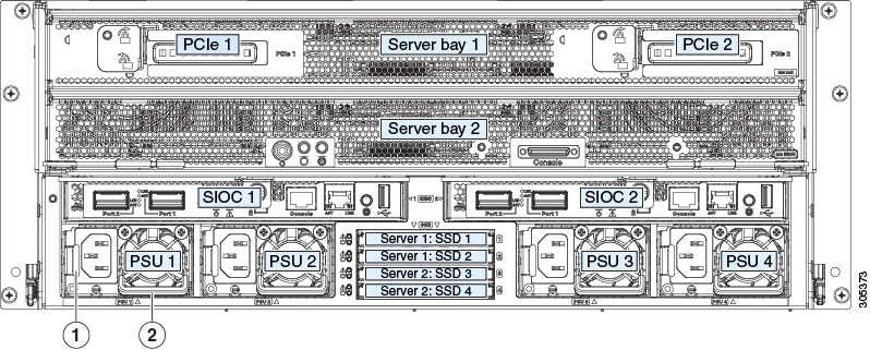
- Remove the power supply that you are replacing or a blank panel from an empty bay (see Figure 3-16:
- Install a new power supply:
DETAILED STEPS
| Command or Action | Purpose | |||||
|---|---|---|---|---|---|---|
|
Step 1 |
Remove the power supply that you are replacing or a blank panel from an empty bay (see Figure 3-16: |
|
||||
|
Step 2 |
Install a new power supply: |
|
Installing a DC Power Supply (First-Time Installation)
Warning |
A readily accessible two-poled disconnect device must be incorporated in the fixed wiring. Statement 1022 |
Warning |
This product requires short-circuit (overcurrent) protection, to be provided as part of the building installation. Install only in accordance with national and local wiring regulations. Statement 1045 |
Warning |
Installation of the equipment must comply with local and national electrical codes. Statement 1074 |
Caution |
Before beginning this wiring procedure, turn off the DC power source from your facility’s circuit breaker to avoid electric shock hazard. |
SUMMARY STEPS
- Turn off the DC power source from your facility’s circuit breaker to avoid electric shock hazard.
- Wire the non-terminated end of the cable to your facility’s DC power input source.
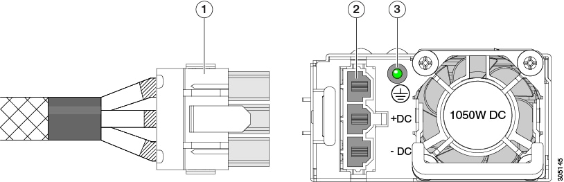
- Connect the terminated end of the cable to the socket on the power supply. The connector is keyed so that the wires align for correct polarity and ground, as shown in Figure 3-17.
- Return DC power from your facility’s circuit breaker.
DETAILED STEPS
| Command or Action | Purpose | |||||||||
|---|---|---|---|---|---|---|---|---|---|---|
|
Step 1 |
Turn off the DC power source from your facility’s circuit breaker to avoid electric shock hazard. |
|
||||||||
|
Step 2 |
Wire the non-terminated end of the cable to your facility’s DC power input source. |
|||||||||
|
Step 3 |
Connect the terminated end of the cable to the socket on the power supply. The connector is keyed so that the wires align for correct polarity and ground, as shown in Figure 3-17. |
|||||||||
|
Step 4 |
Return DC power from your facility’s circuit breaker. |
|
Replacing a DC Power Supply
Note |
You do not have to power off the system to replace up to one power supply because they are redundant as 3+1. |
SUMMARY STEPS
- Remove the power supply that you are replacing or a blank panel from an empty bay:
- Install a new power supply:
DETAILED STEPS
| Command or Action | Purpose | |
|---|---|---|
|
Step 1 |
Remove the power supply that you are replacing or a blank panel from an empty bay: |
|
|
Step 2 |
Install a new power supply: |
|
Replacing DIMMs Inside a Server Node
To replace DIMMs inside a server node, see the service note for your server node:
Replacing CPUs and Heatsinks Inside a Server Node
To replace a storage controller card inside a server node, see the service note for your server node:
Replacing a Storage Controller Card Inside the Server Node
To replace a storage controller card inside a server node, see the service note for your server node:
Replacing an SSD Inside the Server Node (C3X60 M4 or S3260 M5 Only)
To replace a solid state drive (SSD) inside a C3X60 M4 or S3260 M5 server node, see the service note for your server node:
Replacing an RTC Battery Inside the Server Node
To replace an RTC battery inside a server node, see the service note for your server node:
Replacing an Internal USB Drive Inside the Server Node (C3X60 M3 Only)
For instructions on replacing an internal USB drive inside a C3X60 M3 server node, and for enabling or disabling the USB port, see the C3X60 M3 service note:
Installing a Trusted Platform Module (TPM) Inside the Server Node
To install a TPM inside a server node, see the service note for your server node:
Replacing an I/O Expander (C3X60 M4 or S3260 M5 Server Nodes Only)
The C3X60 M4 or S3260 M5 server node might have an optional I/O expander attached to its top. To replace an I/O expander, see the service note for your server node:
Replacing a PCIe Card Inside the I/O Expander (C3X60 M4 or S3260 M5 Server Nodes Only)
To replace a PCIe card inside an optional I/O expander, see the service note for your server node:
Replacing a Storage Controller Card Inside the I/O Expander (C3X60 M4 Server Nodes Only)
To replace a storage controller card inside an optional I/O expander, see the service note for the Cisco UCS C3000 M4 server node:
Replacing an NVMe SSD Inside the I/O Expander (C3X60 M4 or S3260 M5 Server Nodes Only)
To replace a PCIe card inside an optional I/O expander, see the service note for your server node:
Replacing an RTC Battery Inside the S3260 SIOC
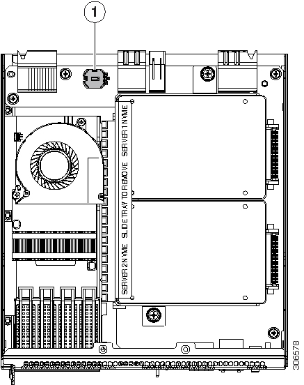
The real-time clock (RTC) battery retains settings when the SIOC is disconnected from power. The battery type in the SIOC is CR1632. Cisco supports the industry-standard CR1632 battery, which can be purchased from most electronic stores.
Note |
When the RTC battery is removed or it completely loses power, settings that were stored in the CMC of the SIOC are lost. You must reconfigure the CMC settings after installing a new battery. |
SUMMARY STEPS
- Power off the connected server nodes based on the scenario:
- Remove the SIOC from the system:
- Remove the SIOC cover as described in Removing the System I/O Controller (SIOC) Cover.
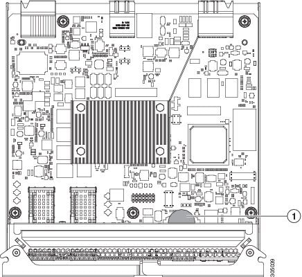
- Gently pry under the battery to lift it from its socket on the SIOC board.
- Insert the new battery into the socket and then press down until it sits flat.
- Replace the cover to the SIOC.
- Replace the SIOC to the system:
- Power on the server node that you powered off earlier.
- Reconfigure the settings of the CMC in this SIOC.
DETAILED STEPS
| Command or Action | Purpose | |||||||||
|---|---|---|---|---|---|---|---|---|---|---|
|
Step 1 |
Power off the connected server nodes based on the scenario: |
|
||||||||
|
Step 2 |
Remove the SIOC from the system: |
|
||||||||
|
Step 3 |
Remove the SIOC cover as described in Removing the System I/O Controller (SIOC) Cover. |
|||||||||
|
Step 4 |
Gently pry under the battery to lift it from its socket on the SIOC board. |
|
||||||||
|
Step 5 |
Insert the new battery into the socket and then press down until it sits flat. |
|||||||||
|
Step 6 |
Replace the cover to the SIOC. |
|||||||||
|
Step 7 |
Replace the SIOC to the system: |
|
||||||||
|
Step 8 |
Power on the server node that you powered off earlier. |
|||||||||
|
Step 9 |
Reconfigure the settings of the CMC in this SIOC. |
|
Replacing a PCIe Adapter Card Inside the S3260 SIOC (Version 03 SIOC Only)
The Version 03 SIOC uses a removable PCIe adapter card that plugs into a horizontal socket. (The version 02 SIOC uses an embedded chip and so does not have a removable adapter card.)
Cisco VIC Cards Supported in Version 03 SIOC (UCSC-S3260-PCISIOC)
At this time, the following Cisco Virtual Interface Cards (VICs) are supported in the Version 03 SIOC:
-
• Cisco UCS VIC 1455 (UCSC-PCIE-C25Q-04)
-
• Cisco UCS VIC 1495 (UCSC-PCIE-C100-04)
Note |
If your S3260 system has two Version 03 SIOCs, the adapter card in each must be identical. Do not mix adapter cards between Version 03 SIOCs. |
SUMMARY STEPS
- Power off the connected server nodes based on the scenario:
- Remove the SIOC from the system:
- Remove the SIOC cover as described in Removing the System I/O Controller (SIOC) Cover, page 3-13.
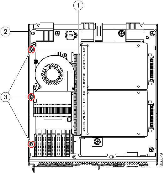
- Remove an existing adapter card:
- Install a new adapter card:
- Turn the SIOC over and reinstall the SIOC cover. Install the six screws that secure the cover.
- Replace the SIOC to the system:
- Power on the server node that you powered off earlier.
DETAILED STEPS
| Command or Action | Purpose | |||||||||
|---|---|---|---|---|---|---|---|---|---|---|
|
Step 1 |
Power off the connected server nodes based on the scenario: |
See Shutting Down an Individual Server Node, page 3-10. |
||||||||
|
Step 2 |
Remove the SIOC from the system: |
|
||||||||
|
Step 3 |
Remove the SIOC cover as described in Removing the System I/O Controller (SIOC) Cover, page 3-13. |
|||||||||
|
Step 4 |
Remove an existing adapter card: |
|
||||||||
|
Step 5 |
Install a new adapter card: |
|
||||||||
|
Step 6 |
Turn the SIOC over and reinstall the SIOC cover. Install the six screws that secure the cover. |
|||||||||
|
Step 7 |
Replace the SIOC to the system: |
|
||||||||
|
Step 8 |
Power on the server node that you powered off earlier. |
|
Replacing an NVMe SSD Inside the S3260 SIOC (Version 03 SIOC Only)
SIOC NVMe SSD Population Rules
The Version 03 SIOC can contain up to two 2.5-inch NVMe SSDs in a sled assembly. You must remove the sled when installing or replacing the SSDs.
Each NVMe SSD slot in a SIOC is numbered for the server that supports it (SERVER 1 NVME or SERVER 2 NVME).
-
Populate an NVMe SSD in SERVER 1 NVME only if you have a server node in upper server bay 1.
-
Populate an NVME SSD in SERVER 2 NVME only if you have a server node in lower server bay 2.
Note |
If your system configuration has an M5 server node in lower server bay 2 and an I/O expander in upper server bay 1, you cannot populate an NVMe SSD in the SERVER 1 NVME slot in either SIOC. See Figure 3-21and Figure 3-22 for illustrations of the system connectivity and labeling. |
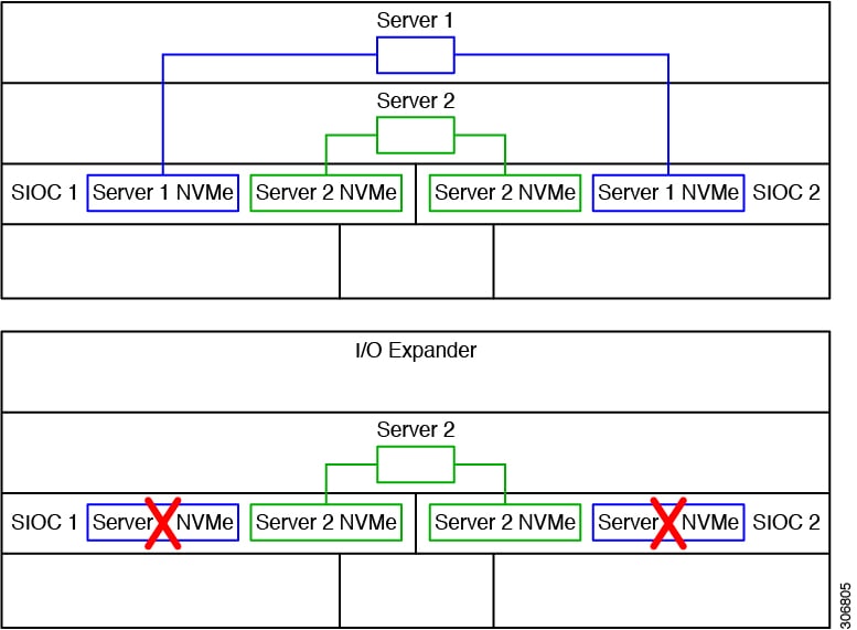
Procedure
SUMMARY STEPS
- Power off the connected server nodes based on the scenario:
- Remove the SIOC from the system:
- Remove the SIOC cover as described in Removing the System I/O Controller (SIOC) Cover.
- Remove the NVMe SSD sled assembly from the SIOC.
DETAILED STEPS
| Command or Action | Purpose | |||||||||
|---|---|---|---|---|---|---|---|---|---|---|
|
Step 1 |
Power off the connected server nodes based on the scenario: |
|
||||||||
|
Step 2 |
Remove the SIOC from the system: |
|
||||||||
|
Step 3 |
Remove the SIOC cover as described in Removing the System I/O Controller (SIOC) Cover. |
|
||||||||
|
Step 4 |
Remove the NVMe SSD sled assembly from the SIOC. |
Loosen the two captive thumbscrews that secure the sled to the SIOC floor and then pull the sled so that the connectors on any installed SSDs disengage from the two sockets on the SIOC board. 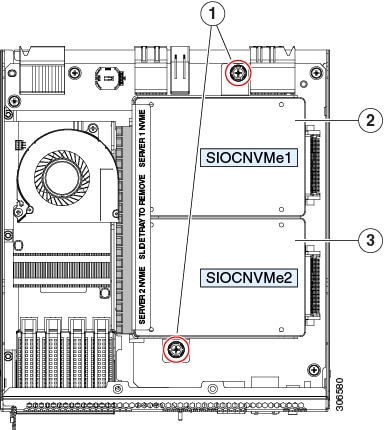
|
Replacing an S3260 Chassis
This procedure is for replacing an S3260 chassis and transferring all components to the new chassis.
SUMMARY STEPS
- Export the component configurations (CMC, BMC, VIC adapters) and save them to a local computer using the import-export command mode.
- Perform a graceful shutdown of all server nodes.
- Disconnect all power cables from all power supplies to fully remove power from the chassis.
- Remove each server node and install each to the same bay position in the new chassis.
- If the system has a disk expansion tray in place of a server node, remove it with its disks in place and install the tray with disks to the same bay position in the new chassis.
- Remove each SIOC and install each to the same bay position in the new chassis.
- Remove each rear-panel boot SSD and install each to the same bay position in the new chassis.
- Remove each power supply and install each to the same bay position in the new chassis.
- Open the main chassis top cover on the old and new chassis.
- Remove each top-loading hard drive and install each to the same bay position in the new chassis.
- Open the fan compartment cover on the old and new chassis.
- Remove each cooling fan and install each to the same bay position in the new chassis.
- If you have not done so already, remove the empty chassis from your rack.
- Close all covers on the new chassis.
- Install the new chassis to your rack.
- Power on, connect cables to the system, and log in to the Cisco IMC Configuration Utility as described in Connecting the System and Opening the Setup Utility.
- Configure the network settings for the system as described in Setting Up the System Using the Cisco IMC Configuration Utility.
- After the system has connection to the network, use the Host Upgrade Utility to update the system to your desired level and ensure that all components in the system are running compatible software levels.
- Import the component configurations that you exported in step 1.
- Verify that all configurations imported successfully.
- Verify that chassis health is optimal.
DETAILED STEPS
| Command or Action | Purpose | |||||
|---|---|---|---|---|---|---|
|
Step 1 |
Export the component configurations (CMC, BMC, VIC adapters) and save them to a local computer using the import-export command mode. |
Refer to the Cisco UCS Integrated Management Controller CLI Configuration Guide for S3260 Storage Servers. See the chapter, Server Utilities and the section, Exporting and Importing the Cisco IMC and BMC Configuration. |
||||
|
Step 2 |
Perform a graceful shutdown of all server nodes. |
See Shutting Down an Individual Server Node for more information. |
||||
|
Step 3 |
Disconnect all power cables from all power supplies to fully remove power from the chassis. |
|||||
|
Step 4 |
Remove each server node and install each to the same bay position in the new chassis. |
If a server node has an I/O expander attached, move the node and expander attached together. See the service note for your server node version for more information: Server Node Service Notes. |
||||
|
Step 5 |
If the system has a disk expansion tray in place of a server node, remove it with its disks in place and install the tray with disks to the same bay position in the new chassis. |
See Replacing a Disk Expansion Tray for more information. |
||||
|
Step 6 |
Remove each SIOC and install each to the same bay position in the new chassis. |
See Replacing a System I/O Controller (SIOC)for more information. |
||||
|
Step 7 |
Remove each rear-panel boot SSD and install each to the same bay position in the new chassis. |
See Replacing SAS/SATA Solid State Drives in the Rear Panel Bays for more information. |
||||
|
Step 8 |
Remove each power supply and install each to the same bay position in the new chassis. |
See Replacing a Power Supply for more information. |
||||
|
Step 9 |
Open the main chassis top cover on the old and new chassis. |
See Opening the Main Chassis Top Covers for more information. |
||||
|
Step 10 |
Remove each top-loading hard drive and install each to the same bay position in the new chassis. |
See Replacing HDDs or SSDs in the Internal Drive Compartment for more information. |
||||
|
Step 11 |
Open the fan compartment cover on the old and new chassis. |
|||||
|
Step 12 |
Remove each cooling fan and install each to the same bay position in the new chassis. |
See Replacing Fan Modules for more information. |
||||
|
Step 13 |
If you have not done so already, remove the empty chassis from your rack. |
|||||
|
Step 14 |
Close all covers on the new chassis. |
|||||
|
Step 15 |
Install the new chassis to your rack. |
See Installing the System in a Rack for instructions.
|
||||
|
Step 16 |
Power on, connect cables to the system, and log in to the Cisco IMC Configuration Utility as described in Connecting the System and Opening the Setup Utility. |
|||||
|
Step 17 |
Configure the network settings for the system as described in Setting Up the System Using the Cisco IMC Configuration Utility. |
|
||||
|
Step 18 |
After the system has connection to the network, use the Host Upgrade Utility to update the system to your desired level and ensure that all components in the system are running compatible software levels. |
See the Cisco Host Upgrade Utility User Guide For S3260 Storage Servers for instructions. |
||||
|
Step 19 |
Import the component configurations that you exported in step 1. |
Refer to the Cisco UCS Integrated Management Controller CLI Configuration Guide for S3260 Storage Servers. See the chapter Server Utilities and the section Exporting and Importing the Cisco IMC and BMC Configuration. |
||||
|
Step 20 |
Verify that all configurations imported successfully. |
|||||
|
Step 21 |
Verify that chassis health is optimal. |
 Feedback