Upgrading to Cisco UCS S3260 System With S3260 M5 Server Nodes

Differences Between Cisco UCS C3160 and S3260 Systems

Table E-1 lists the differences between Cisco UCS C3160 and Cisco UCS S3260 systems.

Table 1. Table E-1 Differences Between Cisco UCS C3160 and Cisco UCS S3260 Systems

System

Cisco IMC Min.

UCS Manager Min.

UCSM- Managed or Standalone

Supported SIOC

Number of Server Nodes Supported

Rear-Panel SSD Drives Supported

I/O Expander Module Support

Storage Controller Card Support

M3 server node

2.0(3)

NA

Standalone only

UCSC-C3160-SIOC Removable adapter card

One M3 server node

(Intel Xeon v2-based)

2

No

One in server node:

  • UCSC-C3X60-R1GB

  • UCSC-C3X60-R4GB

  • UCSC-C3X60-HBA

C3260 with M3 server nodes

2.0(7)

3.1(2)

Standalone or UCSM mode

UCSC-S3260-SIOC

Integrated VIC 1300 Series chip

One or two M3 server nodes

(Intel Xeon v2-based)

4

No

One in each server node:

  • UCSC-C3X60-R1GB

  • UCSC-C3X60-R4GB

  • UCSC-C3X60-HBA

S3260 with M4 server nodes

2.0(13)

3.1(2)

Standalone or UCSM mode

UCSC-S3260-SIOC

Integrated VIC 1300 Series chip

One or two M4 server nodes

(Intel Xeon v4-based)

4

Yes

Rules for server node and I/O expander:

  • UCS-C3K-M4RAID

  • UCS-S3260-DHBA

  • If server node has DHBA, then no controller in I/O.

  • If server node has M4RAID, then I/O can have M4RAID (not DHBA).

  • If server node has no controller, I/O can have DHBA or M4RAID.

S3260 with M5 server nodes

3.1(3)

3.2(3)

Standalone or UCSM mode

  • UCSC-S3260-SIOC Integrated VIC 1300 Series chip

  • UCS-S3260-PCISIOC Removable adapter card

Note


This SIOC requires Cisco IMC & UCS Manager 4.0(1n) or later.

One or two M5 server nodes

(Intel Xeon Scalable Processor Family v1-based)

4

Yes

One in server node only (not in I/O expander):

  • UCS-S3260-DHBA

  • UCS-S3260-DRAID

S3260 with M5 server nodes

3.1(3)

3.2(3)

Standalone or UCSM mode

  • UCSC-S3260-SIOC Integrated VIC 1300 Series chip

  • UCS-S3260-PCISIOC Removable adapter card

Note


This SIOC requires Cisco IMC & UCS Manager 4.0(1n) or later.

One or two M5 server nodes

(Intel Xeon Scalable Processor Family v1-based)

4

Yes

One in server node only (not in I/O expander):

  • UCS-S3260-DHBA

  • UCS-S3260-DRAID


Note


Migration of S3260 to C3160 is not supported. After you migrate a C3160 to a S3260, you cannot reverse the migration back to C3160.


Upgrading From S3260 With One M4 Server Node to S3260 With One M5 Server Node

This procedure upgrades a Cisco UCS S3260 system that is using one C3X60 M4 server node to a Cisco UCS S3260 system that uses one S3260 M5 server node.


Note


The OS and data on any NVMe SSDs in the M4 server node will be lost during the upgrade to M5 server node. The M4 and M5 server nodes have different form factor NVMe SSDs.


Items Required For This Upgrade

Hardware

  • A Cisco UCS S3260 system with one M4 server node and one SIOC. All chassis and server node components must be running Cisco IMC 3.0(3e) firmware before you begin the upgrade.


    Note


    Migration to S3260 with M5 server nodes is supported only with chassis part-number versions 68-5286-06 and later. The motherboard in these chassis versions supports all M5 system components.


  • New M5 server node running Cisco IMC 3.1(3x) or later firmware (the factory default).

Software

  • Up to five IP addresses, either configured in your DHCP server or manually entered for static IP addresses. See System IP Addresses for more information.

  • The latest Host Upgrade Utility package for Cisco IMC 3.0(3e) firmware. This is used to update the entire Cisco S3260 system with M4 node to the prerequisite firmware.

  • The Host Upgrade Utility package for Cisco IMC 3.1(3x) or later firmware. This is used to upgrade the system to M5 server node requirements.

    For instructions on downloading and using the utility, see the instructions in the guide for your release: HUU Guides.

Upgrade Considerations

Note the following considerations:

  • After the upgrade, you must manually define drive zoning to map the hard drives to the individual server node.

  • After the upgrade, your boot SSDs might lose their operating system. In this case, reinstall your operating system to the boot SSDs.

  • The OS and data on any NVMe SSDs in the M4 server node will be lost during the upgrade to M5 server node. The M4 and M5 server nodes have different form factor NVMe SSDs.

Upgrade Procedure

Procedure Summary

SUMMARY STEPS

    Procedure Summary
  1. Ensure that the entire S3260 system with M4 server node is running 3.0(3e).
  2. Disconnect all power cords to remove power from the system.
  3. Replace the M4 server node with an M5 server node.
  4. Reconnect cables and power cords.
  5. Upgrade the entire S3260 system with M5 server node to 3.1(3x).
  6. Boot the system and set CMC and BMC to factory defaults.
  7. Configure IP addresses and network settings.
  8. Perform drive zoning for hard drives.

DETAILED STEPS

Procedure Summary
  Command or Action Purpose

Step 1

Ensure that the entire S3260 system with M4 server node is running 3.0(3e).

Step 2

Disconnect all power cords to remove power from the system.

Step 3

Replace the M4 server node with an M5 server node.

Step 4

Reconnect cables and power cords.

Step 5

Upgrade the entire S3260 system with M5 server node to 3.1(3x).

Step 6

Boot the system and set CMC and BMC to factory defaults.

Step 7

Configure IP addresses and network settings.

Step 8

Perform drive zoning for hard drives.

Upgrading an S3260 System With M4 Server node to S3260 with M5 Server Node


Caution


You must upgrade your system firmware to the required minimum level before you upgrade to M5 server nodes. Older firmware versions cannot recognize the new CPUs and this results in a non-bootable server.


Note


Make sure that Server SIOC Connectivity is set to Single Server Single SIOC in the Cisco IMC before starting this procedure.


Procedure


Step 1

Ensure that the entire Cisco S3260 system with M4 server node is running Cisco IMC 3.0(3e) firmware before you begin the upgrade.

If the system is running an earlier version, download and run the S3260 Host Upgrade Utility (HUU) for release 3.0(3e): HUU Guides .

Step 2

Shut down and remove power from the entire system. You must disconnect all power cords to completely remove power.

Step 3

Remove the existing M4 server node and replace it with a new M5 server node in either server bay.

If your M5 server node has an I/O expander attached to its top, install it attached to the server node.

See Replacing a Server Node for instructions.

Step 4

If your system has only one SIOC, ensure that it is in the correct SIOC bay to communicate with the M5 server node that you just installed:

  • If your single server node is in upper server bay 1, a SIOC must be installed in SIOC bay 1.

  • If your single server node is in lower server bay 2, a SIOC must be installed in SIOC bay 2.

Step 5

If your system has rear panel SSDs, ensure that they are in the correct SSD bays to communicate with the M5 server node that you just installed:

  • If your single server node is in server bay 1, only Server 1 bays SSD1 and SSD2 can be used.

  • If your single server node is in server bay 2, only Server 2 bays SSD1 and SSD2 can be used.

Step 6

Reconnect power cables to the system. Wait for approximately five minutes to allow the system to boot up.

Step 7

Use the S3260 HUU for 3.1(3x) to upgrade the entire system to Cisco IMC release 3.1(3x).

Note


Use the from the S3260 downloads page, not the C3160 downloads page.

Step 8

Verify that all components were upgraded to Cisco IMC 3.1(3x).

Check the firmware versions for the CMC, BMC, BIOS, SAS expander, and SIOC adapter.

Step 9

Connect a KVM cable (Cisco PID N20-BKVM) to the KVM connector on the server node at the rear of the system. Connect a USB keyboard and a VGA monitor to the KVM cable.

Step 10

Open the Cisco IMC Configuration Utility:

  1. Press and hold the front panel power button for four seconds to boot the system. Watch the screen for the prompt to press F8.

  2. During bootup, press F8 when prompted to open the Cisco IMC Configuration Utility.

This utility has three windows that you can toggle between by pressing F1 or F2.

Step 11

The utility prompts you to change the default user password. Set a default user password before continuing. The following are the requirements for Strong Password:

  • The password can have minimum 8 characters; maximum 14 characters.

  • The password must not contain the user’s name.

  • The password must contain characters from three of the following four categories:

    • – English uppercase letters (A through Z).

    • – English lowercase letters (a through z).

    • – Base 10 digits (0 through 9).

    • – Non-alphabetic characters !, @, #, $, %, ^, &, *, -, _, =, “

Step 12

Set the CMCs in all SIOCs and the BMCs in all server nodes to the factory defaults.

The Factory Default check box has two options but you must perform two resets in this order:

  1. Select Chassis Controller Configuration and save your changes. Both CMCs in the SIOCs are set to the factory default state.

  2. Select Server Controller Configuration and save your changes. The server node is set back to its factory default state and the server/host reboots.

Note


The BMC reboots after resetting to defaults. Watch for the prompt to press F8 when the server reboots in the next step.

Step 13

When prompted, press F8 to enter the Cisco IMC Configuration Utility again.

Step 14

Configure the management, CMC, and BMC IP addresses for the system.

Note


If you use a DHCP server and you already have QSFP cables attached to the SIOC, the management IP address and network settings are already filled in. If you disable DHCP, you must set your own static management IP address and network settings.

Step 15

This step is only for setting static IPs (DHCP disabled)—Set the CMC and BMC internal IP addresses by using the Cisco IMC interface, as described in Setting Static CMC and BMC Internal IP Addresses.

Step 16

Use the Cisco IMC (GUI or CLI) to define hard drive zoning, which maps the hard drives to individual server nodes:

Using the Cisco IMC GUI:

  1. Use the IP address of the CMC in either SIOC to log in to the Cisco IMC management software.

  2. Navigate to the following tab:

    Chassis > Inventory > Dynamic Storage > Zoning

  3. Select the drives and then assign them to Server1 or Server2.

Using the Cisco IMC CLI, enter the following commands with your choices:

Server# scope chassis
Server /chassis# scope dynamic-storage
Server /chassis/dynamic-storage# assign-drive <server ID> <drive-slotid-list> 

For example:

Server# scope chassis
Server /chassis # scope dynamic-storage
svbu-huu-sanity-col2-1-vcmc /chassis/dynamic-storage # assign-drive server2 27 
Are you sure you want to assign drives 27 to server2
Enter 'yes' to confirm -> yes
assign-drive operation successful.

Step 17

If you want to add a second server node or SIOC to the system, continue with Installing a Second Server Node or SIOC to the S3260 System With M5 Server Node.


Upgrading a S3260 System With Two M4 Server Nodes to S3260 with Two M5 Server Nodes


Caution


You must upgrade your system firmware to the required minimum level before you upgrade to M5 server nodes. Older firmware versions cannot recognize the new CPUs and this results in a non-bootable server.


Procedure


Step 1

Ensure that the entire Cisco S3260 system with M4 server nodes is running Cisco IMC 3.0(3e) firmware before you begin the upgrade.

If the system is running an earlier version, download and run the S3260 Host Upgrade Utility (HUU) for release 3.0(3e): HUU Guides .

Step 2

Shut down and remove power from the entire system. You must disconnect all power cords to completely remove power.

Step 3

Remove the existing M4 server nodes and replace them with new M5 server nodes.

See Replacing a Server Node for instructions.

Step 4

Reconnect power cables to the system. Wait for approximately five minutes to let the server nodes boot to standby power during the first bootup.

Step 5

Use the S3260 HUU for 3.1(3x) to upgrade the entire system to Cisco IMC release 3.1(3x).

Boot HUU on server node 1 to upgrade the firmware for the SIOC 1 adapter; boot HUU on server node 2 to upgrade the firmware in SIOC 2.

Note


To upgrade firmware on a SIOC adapter, you must boot HUU on the server node that controls that SIOC. Boot HUU on server node 1 to upgrade the firmware for the SIOC 1 adapter; boot HUU on server node 2 to upgrade the firmware in SIOC 2..

Note


Use the HUU from the S3260 downloads page, not the C3160 downloads page.

Step 6

Verify that all components were upgraded to Cisco IMC 3.1(3x).

Check the firmware versions for the CMC, BMC, BIOS, SAS expander, and SIOC adapter.

Step 7

Connect a KVM cable (Cisco PID N20-BKVM) to the KVM connector on the server node at the rear of the system. Connect a USB keyboard and a VGA monitor to the KVM cable.

Step 8

Open the Cisco IMC Configuration Utility:

  1. Press and hold the front panel power button for four seconds to boot the system. Watch the screen for the prompt to press F8.

  2. During bootup, press F8 when prompted to open the Cisco IMC Configuration Utility.

This utility has three windows that you can toggle between by pressing F1 or F2.

Step 9

The utility prompts you to change the default user password. Set a default user password before continuing.

Step 10

Set the CMCs in all SIOCs and the BMCs in all server nodes to the factory defaults.

The Factory Default check box has two options but you must perform two resets in this order:

  1. Select Chassis Controller Configuration and save your changes. Both CMCs in the SIOCs are set to the factory default state.

  2. Select Server Controller Configuration and save your changes. The server node is set back to its factory default state and the server/host reboots.

Note


The BMC reboots after resetting to defaults. Watch for the prompt to press F8 when the server reboots in the next step.

Note


Set the BMC in the second server node to factory defaults also.

Step 11

When prompted, press F8 to enter the Cisco IMC Configuration Utility again.

Step 12

Set a new Cisco IMC password when prompted.

Step 13

Configure the management, CMC, and BMC IP addresses for the system.

Note


If you use a DHCP server and you already have QSFP cables attached to the SIOC, the management IP address and network settings are already filled in. If you disable DHCP, you must set your own static management IP address and network settings.

Step 14

This stepis only for setting static IPs (DHCP disabled)—Set the CMC and BMC internal IP addresses by using the Cisco IMC interface, as described in Setting Static CMC and BMC Internal IP Addresses.

Step 15

Use the Cisco IMC (GUI or CLI) to define hard drive zoning, which maps the hard drives to individual server nodes. Use either the Cisco IMC GUI or the Cisco IMC CLI:

Using the Cisco IMC GUI:

  1. Use the management IP address of the system to log in to the Cisco IMC management software.

  2. Navigate to the following tab:

    Chassis > Inventory > Dynamic Storage > Zoning

  3. Select the drives and then assign them to Server1 or Server2.

Using the Cisco IMC CLI, enter the following commands with your choices:

Server# scope chassis
Server /chassis# scope dynamic-storage
Server /chassis/dynamic-storage# assign-drive <server ID> <drive-slotid-list> 

For example:

Server# scope chassis
Server /chassis # scope dynamic-storage
svbu-huu-sanity-col2-1-vcmc /chassis/dynamic-storage # assign-drive server2 27 
Are you sure you want to assign drives 27 to server2
Enter 'yes' to confirm -> yes
assign-drive operation successful.

Items Required For This Upgrade

Hardware

  • A Cisco UCS S3260 system with two M4 server nodes. All chassis and server node components must be running Cisco IMC 3.0(3e) firmware before you begin the upgrade.


    Note


    Migration to S3260 with M5 server nodes is supported only with chassis part-number versions 68-5286-06 and later. The motherboard in these chassis versions supports all M5 system components.


  • New M5 server nodes running Cisco IMC 3.1(3x) or later firmware (the factory default).

Software

  • Up to five IP addresses, either configured in your DHCP server or manually entered for static IP addresses. See System IP Addresses for more information.

  • The latest Host Upgrade Utility package for Cisco IMC 3.0(3e) firmware. This is used to update the entire Cisco S3260 system with M4 nodes to the prerequisite firmware.

  • The Host Upgrade Utility package for Cisco IMC 3.1(3x) or later firmware. This is used to upgrade the system to M5 server node requirements.

    For instructions on downloading and using the utility, see the instructions in the guide for your release: HUU Guides.

Upgrade Considerations

Note the following considerations:

  • After the upgrade, you must manually define drive zoning to map the hard drives to individual server nodes.

  • After the upgrade, your boot SSDs might lose their operating system. In this case, reinstall your operating system to the boot SSDs.

  • The OS and data on any NVMe SSDs in the M4 server node will be lost during the upgrade to M5 server node. The M4 and M5 server nodes have different form factor NVMe SSDs.

Upgrade Procedure

Procedure

Procedure Summary

Procedure Summary
  Command or Action Purpose

Step 1

Ensure that the entire S3260 system with M4 server node is running 3.0(3e).

Step 2

Disconnect all power cords to remove power from the system.

Step 3

Replace the M4 server node with an M5 server node.

Step 4

Reconnect cables and power cords.

Step 5

Upgrade the entire S3260 system with M5 server node to 3.1(3x).

Step 6

Boot the system and set CMC and BMC to factory defaults.

Step 7

Configure IP addresses and network settings.

Step 8

Perform drive zoning for hard drives.

Upgrading a S3260 System With Two M4 Server Nodes to S3260 with Two M5 Server Nodes


Caution


You must upgrade your system firmware to the required minimum level before you upgrade to M5 server nodes. Older firmware versions cannot recognize the new CPUs and this results in a non-bootable server.


Procedure


Step 1

Ensure that the entire Cisco S3260 system with M4 server nodes is running Cisco IMC 3.0(3e) firmware before you begin the upgrade.

If the system is running an earlier version, download and run the S3260 Host Upgrade Utility (HUU) for release 3.0(3e): HUU Guides .

Step 2

Shut down and remove power from the entire system. You must disconnect all power cords to completely remove power.

Step 3

Remove the existing M4 server nodes and replace them with new M5 server nodes.

See Replacing a Server Node for instructions.

Step 4

Reconnect power cables to the system. Wait for approximately five minutes to let the server nodes boot to standby power during the first bootup.

Step 5

Use the S3260 HUU for 3.1(3x) to upgrade the entire system to Cisco IMC release 3.1(3x).

Boot HUU on server node 1 to upgrade the firmware for the SIOC 1 adapter; boot HUU on server node 2 to upgrade the firmware in SIOC 2.

Note


To upgrade firmware on a SIOC adapter, you must boot HUU on the server node that controls that SIOC. Boot HUU on server node 1 to upgrade the firmware for the SIOC 1 adapter; boot HUU on server node 2 to upgrade the firmware in SIOC 2..

Note


Use the HUU from the S3260 downloads page, not the C3160 downloads page.

Step 6

Verify that all components were upgraded to Cisco IMC 3.1(3x).

Check the firmware versions for the CMC, BMC, BIOS, SAS expander, and SIOC adapter.

Step 7

Connect a KVM cable (Cisco PID N20-BKVM) to the KVM connector on the server node at the rear of the system. Connect a USB keyboard and a VGA monitor to the KVM cable.

Step 8

Open the Cisco IMC Configuration Utility:

  1. Press and hold the front panel power button for four seconds to boot the system. Watch the screen for the prompt to press F8.

  2. During bootup, press F8 when prompted to open the Cisco IMC Configuration Utility.

This utility has three windows that you can toggle between by pressing F1 or F2.

Step 9

The utility prompts you to change the default user password. Set a default user password before continuing.

Step 10

Set the CMCs in all SIOCs and the BMCs in all server nodes to the factory defaults.

The Factory Default check box has two options but you must perform two resets in this order:

  1. Select Chassis Controller Configuration and save your changes. Both CMCs in the SIOCs are set to the factory default state.

  2. Select Server Controller Configuration and save your changes. The server node is set back to its factory default state and the server/host reboots.

Note


The BMC reboots after resetting to defaults. Watch for the prompt to press F8 when the server reboots in the next step.

Note


Set the BMC in the second server node to factory defaults also.

Step 11

When prompted, press F8 to enter the Cisco IMC Configuration Utility again.

Step 12

Set a new Cisco IMC password when prompted.

Step 13

Configure the management, CMC, and BMC IP addresses for the system.

Note


If you use a DHCP server and you already have QSFP cables attached to the SIOC, the management IP address and network settings are already filled in. If you disable DHCP, you must set your own static management IP address and network settings.

Step 14

This stepis only for setting static IPs (DHCP disabled)—Set the CMC and BMC internal IP addresses by using the Cisco IMC interface, as described in Setting Static CMC and BMC Internal IP Addresses.

Step 15

Use the Cisco IMC (GUI or CLI) to define hard drive zoning, which maps the hard drives to individual server nodes. Use either the Cisco IMC GUI or the Cisco IMC CLI:

Using the Cisco IMC GUI:

  1. Use the management IP address of the system to log in to the Cisco IMC management software.

  2. Navigate to the following tab:

    Chassis > Inventory > Dynamic Storage > Zoning

  3. Select the drives and then assign them to Server1 or Server2.

Using the Cisco IMC CLI, enter the following commands with your choices:

Server# scope chassis
Server /chassis# scope dynamic-storage
Server /chassis/dynamic-storage# assign-drive <server ID> <drive-slotid-list> 

For example:

Server# scope chassis
Server /chassis # scope dynamic-storage
svbu-huu-sanity-col2-1-vcmc /chassis/dynamic-storage # assign-drive server2 27 
Are you sure you want to assign drives 27 to server2
Enter 'yes' to confirm -> yes
assign-drive operation successful.

Installing a Second Server Node or SIOC to the S3260 System With M5 Server Node

Installing a Second SIOC

It is important that the CMC firmware in the new S3260 SIOC is the same version as the CMC firmware in the existing SIOC. If the CMC versions are different, you must upgrade them to match.


Note


When the second SIOC is inserted, its chassis management controller (CMC) becomes the standby CMC. If you move a S3260 SIOC from one chassis to another, the SIOC’s CMC configuration is treated as incompatible and is automatically deleted. The new SIOC CMC will sync with the active CMC in the existing SIOC.


SUMMARY STEPS

  1. A second S3260 SIOC can be installed without removing system power:
  2. Attach QSFP cabled to the QSFP ports on the second SIOC.
  3. Assign a CMC IP address to the new SIOC:
  4. Verify that the CMC and adapter firmware in the SIOC matches the firmware in the other SIOC. If they do not match, update the firmware in the SIOCs.

DETAILED STEPS

  Command or Action Purpose

Step 1

A second S3260 SIOC can be installed without removing system power:

Step 2

Attach QSFP cabled to the QSFP ports on the second SIOC.

Note


Note If you are using the Dedicated NIC mode, connect an RJ-45 Ethernet cable to the dedicated management port.

Step 3

Assign a CMC IP address to the new SIOC:

  • If the S3260 system has been configured to use your DHCP server, allow it to assign the CMC IP address to the new SIOC.

  • If you are not using a DHCP server, use the Cisco IMC interface (CLI or GUI) to manually assign a CMC IP address for the new SIOC, as described in Setting Up the System Using the Cisco IMC Configuration Utility.

Step 4

Verify that the CMC and adapter firmware in the SIOC matches the firmware in the other SIOC. If they do not match, update the firmware in the SIOCs.

Installing a Second M4 Server Node

Items Required For This Procedure

  • An M5 server node running Cisco IMC 3.1(3x) or later firmware.

Procedure

SUMMARY STEPS

  1. Verify that the target S3260 system is running Cisco IMC 3.1(3x) or later firmware.
  2. A second server node can be installed without removing system power:
  3. Verify that the server node is manageable from the S3260 Cisco IMC CLI or GUI. If the new server is not displayed in the CLI or GUI, then you must reset the server to factory defaults.
  4. Assign a BMC IP address to the new server node:

DETAILED STEPS

  Command or Action Purpose

Step 1

Verify that the target S3260 system is running Cisco IMC 3.1(3x) or later firmware.

Step 2

A second server node can be installed without removing system power:

  1. If you have a drive expander module or I/O expander in the system, remove it from the system.

    • To remove a drive expander module, see Replacing a Disk Expansion Tray, page 3-27.

    • To remove an I/O expander, you must remove the server node and then detach the I/O expander from it. See Replacing an I/O Expander (C3X60 M4 or S3260 M5 Server Nodes Only), page 3-37.

  2. With the two ejector levers open, align the new server node with the empty bay.

  3. Push the server node into the bay until it engages with the midplane connectors and is flush with the chassis surface.

  4. Rotate both ejector levers toward the center until they lay flat and their latches lock into the rear of the server node.

Step 3

Verify that the server node is manageable from the S3260 Cisco IMC CLI or GUI. If the new server is not displayed in the CLI or GUI, then you must reset the server to factory defaults.

For example using the CLI:

S3260-Server# scope chassis
S3260-Server /chassis# show server
<Server ID> <Power state> <Serial number> <Product name> <PID> <UUID> 
------------------------------------------------------
1 on FCH1848793G UCS S3260 UCSC-C3K-M4SRB 36399C1B-6E9A-4E95-BEAC-B9003DCA6C7F
2 on FCH18407MY2 UCS S3260 UCSC-C3K-M4SRB C00E5CEO-A596-45E0-82CD-0B2F0A395FAC
  • If the server is displayed in the CLI or GUI, go to the next step.

  • If the server is not displayed, set it to factory defaults as descried in the following steps:

    1. Use a KVM cable to attach a monitor and keyboard to the KVM connector on the rear of the server that you just inserted.

    2. Boot the server node and when prompted, press F8 to enter the Cisco IMC Configuration Utility.

    3. Press F1 to go to the second screen of the utility.

    4. Select the Factory Default option for Server Controller Configuration. The selected server node is set back to its factory default state and the selected server/host reboots.

    5. Press F10 to save changes to reboot the server’s BMC.

    6. Wait for the reboot to complete (approximately five minutes).

Step 4

Assign a BMC IP address to the new server node:

  • If the S3260 system has been configured to use your DHCP server, allow it to assign the BMC IP address to the new server node then go to the next step.

  • If you are not using a DHCP server, use the Cisco IMC interface (CLI or GUI) to manually assign a BMC IP address for the new server node.

    For example using the CLI:

    S3260-Server# scope network
    S3260-Server /cimc/network# set v4-addr-bmc<n> <v4 ip-address> 
    S3260-Server /cimc/network# set v6-addr-bmc<n> <v6 ip-address> 

    For more information see Cisco UCS C-Series Integrated Management Controller GUI Configuration Guide for S3260 Servers or the Cisco UCS C-Series Integrated Management Controller CLI Configuration Guide for S3260 Servers here: Configuration Guides.

    The second M5 server node is now ready for use in the S3260 system.

Migrating From Version 02 SIOC to Version 03 SIOC

This procedure describes how to migrate from SIOC Version 02 (UCS-S3260-SIOC) to SIOC Version 03 (UCS-S3260-PCISIOC).

  • The version 02 SIOC (UCSC-S3260-SIOC) uses an integrated Cisco UCS VIC 1300 Series chip on-board, so there is no removable adapter card. There are no storage drives in the SIOC.

  • The Version 03 SIOC (UCS-S3260-PCISIOC) uses a removable PCIe-style adapter card (half-height, half-length, Gen-3, x8 lane). It also supports up to two 2.5-inch NVMe SSDs and an RTC battery.


Note


The Version 03 SIOC is supported only with the S3260 M5 server node. It is not supported with earlier server nodes.


Note


The Version 03 SIOC is supported only with the S3260 M5 server node. It is not supported with earlier server nodes.


Note


VersioVersion 03 SIOCs require Cisco IMC 4.0(1n) or later and Cisco UCS Manager 4.0(1n) or later. The upgrade process is described in the following procedure.n 03 SIOCs require Cisco IMC 4.0(1n) or later and Cisco UCS Manager 4.0(1n) or later. The upgrade process is described in the following procedure.


  1. Ensure that the entire S3260 system with M4 server node is running 3.0(3e).

  2. Disconnect all power cords to remove power from the system.

  3. Replace the M4 server node with an M5 server node.

  4. Reconnect cables and power cords.

  5. Upgrade the entire S3260 system with M5 server node to 3.1(3x).

  6. Boot the system and set CMC and BMC to factory defaults.

  7. Configure IP addresses and network settings.

  8. Perform drive zoning for hard drives.

Procedure

Full Procedure
  Command or Action Purpose

Step 1

Ensure that the entire Cisco S3260 system with M5 server node is running Cisco IMC 3.1(3a) firmware before you begin the upgrade.

If the system is running an earlier version, download and run the S3260 Host Upgrade Utility (HUU) for release 3.1(3a): HUU Guides .

Step 2

Shut down and remove power from the entire system. You must disconnect all power cords to completely remove power.

Step 3

Remove the Version 02 SIOC(s) and install the Version 03 SIOC(s). See Replacing a System I/O Controller (SIOC).

If your system has only one server node, ensure that the SIOC is in the correct SIOC bay to communicate with the server node:

  • If your single server node is in upper server bay 1, a SIOC must be installed in SIOC bay 1.

  • If your single server node is in lower server bay 2, a SIOC must be installed in SIOC bay 2.

Step 4

Reconnect power cables to the system. Wait for approximately five minutes to allow the system to boot.

Step 5

Use the S3260 HUU for 4.0(1x) to upgrade the entire system to Cisco IMC release 4.0(1x).

Step 6

Verify that all components were upgraded to Cisco IMC 4.0(1x).

Check the firmware versions for the CMC, BMC, BIOS, SAS expander, and SIOC adapter.

Step 7

Connect a KVM cable (Cisco PID N20-BKVM) to the KVM connector on the server node at the rear of the system. Connect a USB keyboard and a VGA monitor to the KVM cable.

Step 8

Open the Cisco IMC Configuration Utility:

  1. a. Press and hold the front panel power button for four seconds to boot the system. Watch the screen for the prompt to press F8.

  2. b. During bootup, press F8 when prompted to open the Cisco IMC Configuration Utility. This utility has three windows that you can toggle between by pressing F1 or F2.

Step 9

The utility prompts you to change the default user password. Set a default user password before continuing.

The following are the requirements for Strong Password:

  • The password can have minimum 8 characters; maximum 14 characters.

  • The password must not contain the user’s name.

  • The password must contain characters from three of the following four categories:

    • – English uppercase letters (A through Z).

    • – English lowercase letters (a through z).

    • – Base 10 digits (0 through 9).

    • – Non-alphabetic characters !, @, #, $, %, ^, &, *, -, _, =, “

Step 10

Set the CMCs in all SIOCs and the BMCs in all server nodes to the factory defaults. Step 10 a. b. Note

The Factory Default check box has two options but you must perform two resets in this order:
  1. Select Chassis Controller Configuration and save your changes. Both CMCs in the SIOCs are set to the factory default state.

  2. Select Server Controller Configuration and save your changes. The server node is set back to its factory default state and the server/host reboots.

    Note


    The BMC reboots after resetting to defaults. Watch for the prompt to press F8 when the server reboots in the next step.

Step 11

When prompted, press F8 to enter the Cisco IMC Configuration Utility again.

Step 12

Configure the management, CMC, and BMC IP addresses for the system.

Note


If you use a DHCP server and you already have QSFP cables attached to the SIOC, the management IP address and network settings are already filled in. If you disable DHCP, you must set your own static management IP address and network settings.

Step 13

This step only for setting static IPs (DHCP disabled)—Set the CMC and BMC internal IP addresses by using the Cisco IMC interface, as described in Setting Static CMC and BMC Internal IP Addresses.

Step 14

Use the Cisco IMC (GUI or CLI) to define drive zoning, which maps the NVMe SSD drives in the Version 03 SIOC(s) to individual server nodes:

Note


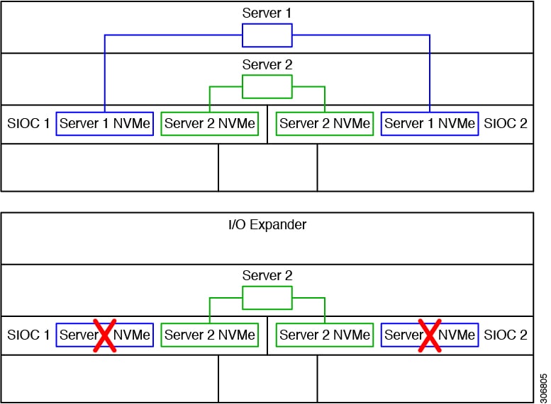
An NVMe SSD in the SIOC slot that is labeled SERVER 1 NVME is supported only by a server node in upper server bay 1. An NVMe SSD in the SIOC slot that is labeled SERVER 2 NVME is supported only by a server node in lower server bay 2. Figure E-1 shows examples of the connectivity. In the lower view, the system has an I/O expander populated in server bay 1 and so the SERVER 1 NVME slots cannot be used.

Figure 1. Figure E-1 NVMe SSD Connectivity in Version 03 SIOC (UCS-S3260-PCISIOC)
  • Using the Cisco IMC GUI:

    1. Use the IP address of the CMC in either SIOC to log in to the Cisco IMC management software.

    2. Navigate to the following tab:

      Chassis > Inventory > Dynamic Storage > Zoning

    3. Select the drives and then assign them to Server1 or Server2.

  • Using the Cisco IMC CLI, enter the following commands with your choices:

    Server# scope chassis
    Server /chassis# scope dynamic-storage
    Server /chassis/dynamic-storage# assign-drive <server ID> <drive-slotid-list>

For example:

Server# scope chassis
Server /chassis # scope dynamic-storage
svbu-huu-sanity-col2-1-vcmc /chassis/dynamic-storage # assign-drive server2 2 
Are you sure you want to assign drives 2 to server2
Enter 'yes' to confirm -> yes
assign-drive operation successful.

Older Migration and Upgrade Procedures

Upgrading From S3260 With One M3 Server Node to S3260 With One M4 Server Node

This procedure upgrades a Cisco UCS S3260 system that is using one C3X60 M3 server node to a Cisco UCS S3260 system that uses one C3X60 M4 server node.

Items Required For This Upgrade

Hardware
  • A Cisco UCS S3260 system with one M3 server node and one SIOC. All chassis and server node components must be running Cisco IMC 2.0(7) or 2.0(9) firmware before you begin the upgrade.


    Note


    Migration to S3260 with M4 server nodes is supported only with chassis part-number versions 68-5286-06 and later. The motherboard in these chassis versions supports all M4 system components.


  • New M4 server nodes running Cisco IMC 2.0(13) or later firmware (the factory default).

Software
  • Up to five IP addresses, either configured in your DHCP server or manually entered for static IP addresses. See System IP Addresses for more information.

  • The latest Host Upgrade Utility package for Cisco IMC 2.0(7) or 2.0(9) firmware. This is used to update the entire Cisco S3260 system with M3 nodes to the prerequisite firmware.

  • The Host Upgrade Utility package for Cisco IMC 2.0(13) or later firmware. This is used to upgrade the system to M4 server node requirements.

    For instructions on downloading and using the utility, see the instructions in the guide for your release: HUU Guides.

Upgrade Procedure

Procedure Summary

SUMMARY STEPS

    Procedure Summary
  1. Ensure that the entire S3260 system with M3 server node is running 2.0(7) or 2.0(9).
  2. Upgrade the entire S3260 system with M3 server node to 2.0(13).
  3. Disconnect all power cords to remove power from the system.
  4. Replace the M3 server node with an M4 server node.
  5. Reconnect cables and power cords.
  6. Boot the system and set CMC and BMC to factory defaults.
  7. Configure IP addresses and network settings.
  8. Perform drive zoning for hard drives.

DETAILED STEPS

Procedure Summary
  Command or Action Purpose

Step 1

Ensure that the entire S3260 system with M3 server node is running 2.0(7) or 2.0(9).

Step 2

Upgrade the entire S3260 system with M3 server node to 2.0(13).

Step 3

Disconnect all power cords to remove power from the system.

Step 4

Replace the M3 server node with an M4 server node.

Step 5

Reconnect cables and power cords.

Step 6

Boot the system and set CMC and BMC to factory defaults.

Step 7

Configure IP addresses and network settings.

Step 8

Perform drive zoning for hard drives.

Upgrading a S3260 System With M3 Server Node to S3260 with M4 Server Node


Caution


You must upgrade your system firmware to the required minimum level before you upgrade to M4 server nodes. Older firmware versions cannot recognize the new CPUs and this results in a non-bootable server.


SUMMARY STEPS

  1. Ensure that the entire Cisco S3260 system with M3 server node is running Cisco IMC 2.0(7) or 2.0(9) firmware before you begin the upgrade.
  2. Use the S3260 HUU for 2.0(13) to upgrade the entire system to Cisco IMC release 2.0(13).
  3. Verify that all components were upgraded to Cisco IMC 2.0(13).
  4. Shut down and remove power from the entire system. You must disconnect all power cords to completely remove power.
  5. Remove the existing M3 server node and replace it with a new M4 server node in either server bay.
  6. If your system has only one SIOC, ensure that it is in the correct SIOC bay to communicate with the M4 server node that you just installed:
  7. If your system has rear panel SSDs, ensure that they are in the correct SSD bays to communicate with the M4 server node that you just installed:
  8. Reconnect power cables to the system. Wait for approximately five minutes to allow the system to boot up.
  9. Connect a KVM cable (Cisco PID N20-BKVM) to the KVM connector on the server node at the rear of the system (See Figure E-3). Connect a USB keyboard and a VGA monitor to the KVM cable.
  10. Open the Cisco IMC Configuration Utility:
  11. The utility prompts you to change the default user password. Set a default user password before continuing.
  12. Set the CMCs in all SIOCs and the BMCs in all server nodes to the factory defaults.
  13. When prompted, press F8 to enter the Cisco IMC Configuration Utility again.
  14. Set a new Cisco IMC password when prompted.
  15. Configure the management, CMC, and BMC IP addresses for the system.
  16. This step is only for setting static IPs (DHCP disabled)—Set the CMC and BMC internal IP addresses by using the Cisco IMC interface, as described in Setting Static CMC and BMC Internal IP Addresses.
  17. Use the Cisco IMC (GUI or CLI) to define hard drive zoning, which maps the hard drives to individual server nodes:
  18. If you want to add a second server node or SIOC to the system, continue with Installing a Second Server Node or SIOC to the S3260 System With M4 Server Nodes.

DETAILED STEPS


Step 1

Ensure that the entire Cisco S3260 system with M3 server node is running Cisco IMC 2.0(7) or 2.0(9) firmware before you begin the upgrade.

If the system is running an earlier version, download and run the S3260 Host Upgrade Utility (HUU) for release 2.0(7) or 2.0(9). Use the Host Upgrade Utility User Guide for release 2.0(7) or 2.0(9) for instructions on downloading and using the utility: HUU Guides .

Step 2

Use the S3260 HUU for 2.0(13) to upgrade the entire system to Cisco IMC release 2.0(13).

Note


Use the 2.0(13) HUU from the S3260 downloads page, not the C3160 downloads page.

Step 3

Verify that all components were upgraded to Cisco IMC 2.0(13).

Check the firmware versions for the CMC, BMC, BIOS, SAS expander, and SIOC adapter.

Step 4

Shut down and remove power from the entire system. You must disconnect all power cords to completely remove power.

Step 5

Remove the existing M3 server node and replace it with a new M4 server node in either server bay.

If your M4 server node has an I/O expander attached to its top, install them together with the server node in server bay 2.

See Replacing a Server Node for instructions.

Step 6

If your system has only one SIOC, ensure that it is in the correct SIOC bay to communicate with the M4 server node that you just installed:

  • If your single server node is in server bay 1 see Figure E-2, a SIOC must be installed in SIOC bay 1.

  • If your single server node is in server bay 2, a SIOC must be installed in SIOC bay 2.

Step 7

If your system has rear panel SSDs, ensure that they are in the correct SSD bays to communicate with the M4 server node that you just installed:

  • If your single server node is in server bay 1 9See Figure E-20, only Server 1 bays SSD1 and SSD2 can be used.

  • If your single server node is in server bay 2, only Server 2 bays SSD1 and SSD2 can be used.

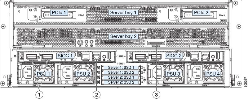
Figure 2. Figure E-2 Rear Panel Connectors for Setup

1

40-Gb QSFP ports (two on each SIOC)

3

KVM console connector on each server node

2

10/100/1000 dedicated management port

-

-

Step 8

Reconnect power cables to the system. Wait for approximately five minutes to allow the system to boot up.

Step 9

Connect a KVM cable (Cisco PID N20-BKVM) to the KVM connector on the server node at the rear of the system (See Figure E-3). Connect a USB keyboard and a VGA monitor to the KVM cable.

Step 10

Open the Cisco IMC Configuration Utility:

  1. Press and hold the front panel power button for four seconds to boot the system. Watch the screen for the prompt to press F8.

  2. During bootup, press F8 when prompted to open the Cisco IMC Configuration Utility.

This utility has three windows that you can toggle between by pressing F1 or F2.

Step 11

The utility prompts you to change the default user password. Set a default user password before continuing.

Step 12

Set the CMCs in all SIOCs and the BMCs in all server nodes to the factory defaults.

The Factory Default check box has two options but you must perform two resets in this order:

  1. Select Chassis Controller Configuration and save your changes. Both CMCs in the SIOCs are set to the factory default state.

  2. Select Server Controller Configuration and save your changes. The server node is set back to its factory default state and the server/host reboots.

Note


The BMC reboots after resetting to defaults. Watch for the prompt to press F8 when the server reboots in the next step.

Step 13

When prompted, press F8 to enter the Cisco IMC Configuration Utility again.

Step 14

Set a new Cisco IMC password when prompted.

Step 15

Configure the management, CMC, and BMC IP addresses for the system.

Note


If you use a DHCP server and you already have QSFP cables attached to the SIOC, the management IP address and network settings are already filled in. If you disable DHCP, you must set your own static management IP address and network settings.

Step 16

This step is only for setting static IPs (DHCP disabled)—Set the CMC and BMC internal IP addresses by using the Cisco IMC interface, as described in Setting Static CMC and BMC Internal IP Addresses.

Step 17

Use the Cisco IMC (GUI or CLI) to define hard drive zoning, which maps the hard drives to individual server nodes:

Using the Cisco IMC GUI:

  1. Use the IP address of the CMC in either SIOC to log in to the Cisco IMC management software.

  2. Navigate to the following tab:

    Chassis > Inventory > Dynamic Storage > Zoning

  3. Select the drives and then assign them to Server1 or Server2.

Using the Cisco IMC CLI, enter the following commands with your choices:

Server# scope chassis
Server /chassis# scope dynamic-storage
Server /chassis/dynamic-storage# assign-drive <server ID> <drive-slotid-list> 

For example:

Server# scope chassis
Server /chassis # scope dynamic-storage
svbu-huu-sanity-col2-1-vcmc /chassis/dynamic-storage # assign-drive server2 27 
Are you sure you want to assign drives 27 to server2
Enter 'yes' to confirm -> yes
assign-drive operation successful.

Step 18

If you want to add a second server node or SIOC to the system, continue with Installing a Second Server Node or SIOC to the S3260 System With M4 Server Nodes.


Upgrading From S3260 With Two M3 Server Nodes to S3260 With Two M4 Server Nodes

This procedure upgrades a Cisco UCS S3260 system that is using two C3X60 M3 server nodes to a Cisco UCS S3260 system that uses two C3X60 M4 server nodes.

Items Required For This Upgrade

Hardware
  • A Cisco UCS S3260 system with two M3 server nodes. All chassis and server node components must be running Cisco IMC 2.0(7) or 2.0(9) firmware before you begin the upgrade.


    Note


    Migration to S3260 with M4 server nodes is supported only with chassis part-number versions 68-5286-06 and later. The motherboard in these chassis versions supports all M4 system components.


  • New M4 server nodes running Cisco IMC 2.0(13) or later firmware (the factory default).

Software
  • Up to five IP addresses, either configured in your DHCP server or manually entered for static IP addresses. See System IP Addresses for more information.

  • The latest Host Upgrade Utility package for Cisco IMC 2.0(7) or 2.0(9) firmware. This is used to update the entire Cisco S3260 system with M3 nodes to the prerequisite firmware.

  • The Host Upgrade Utility package for Cisco IMC 2.0(13) or later firmware. This is used to upgrade the system to M4 server node requirements.

    For instructions on downloading and using the utility, see the instructions in the guide for your release: HUU Guides.

Upgrade Considerations

Note the following considerations:

  • After the upgrade, you must manually define drive zoning to map the hard drives to the individual server nodes.

  • After the upgrade, your boot SSDs might lose their operating system. In this case, reinstall your operating system to the boot SSDs.

Upgrade Procedure

Procedure Summary

SUMMARY STEPS

    Procedure Summary
  1. Ensure that the entire S3260 system with M3 server nodes is running 2.0(7) or 2.0(9).
  2. Upgrade the entire S3260 system with M3 server nodes to 2.0(13).
  3. Disconnect all power cords to remove power from the system.
  4. Replace the M3 server nodes with M4 server nodes.
  5. Reconnect cables and power cords.
  6. Boot the system and set CMC and BMC to factory defaults.
  7. Configure IP addresses and network settings.
  8. Perform drive zoning for hard drives.

DETAILED STEPS

Procedure Summary
  Command or Action Purpose

Step 1

Ensure that the entire S3260 system with M3 server nodes is running 2.0(7) or 2.0(9).

Step 2

Upgrade the entire S3260 system with M3 server nodes to 2.0(13).

Step 3

Disconnect all power cords to remove power from the system.

Step 4

Replace the M3 server nodes with M4 server nodes.

Step 5

Reconnect cables and power cords.

Step 6

Boot the system and set CMC and BMC to factory defaults.

Step 7

Configure IP addresses and network settings.

Step 8

Perform drive zoning for hard drives.

Upgrading a S3260 System With Two M3 Server Nodes to S3260 with Two M4 Server Nodes


Caution


You must upgrade your system firmware to the required minimum level before you upgrade to M4 server nodes. Older firmware versions cannot recognize the new CPUs and this results in a non-bootable server.


SUMMARY STEPS

  1. Ensure that the entire Cisco S3260 system with M3 server node is running Cisco IMC 2.0(7) or 2.0(9) firmware before you begin the upgrade.
  2. Use the S3260 HUU for 2.0(13) to upgrade the entire system to Cisco IMC release 2.0(13).
  3. Verify that all components were upgraded to Cisco IMC 2.0(13).
  4. Shut down and remove power from the entire system. You must disconnect all power cords to completely remove power.
  5. Remove the existing M3 server node and replace them with new M4 server nodes.
  6. Reconnect power cables to the system. Wait for approximately five minutes to allow the system to boot up.
  7. Connect a KVM cable (Cisco PID N20-BKVM) to the KVM connector on the server node at the rear of the system (See Figure E-3). Connect a USB keyboard and a VGA monitor to the KVM cable.
  8. Open the Cisco IMC Configuration Utility:
  9. The utility prompts you to change the default user password. Set a default user password before continuing.
  10. Set the CMCs in all SIOCs and the BMCs in all server nodes to the factory defaults.
  11. When prompted, press F8 to enter the Cisco IMC Configuration Utility again.
  12. Set a new Cisco IMC password when prompted.
  13. Configure the management, CMC, and BMC IP addresses for the system.
  14. This step is only for setting static IPs (DHCP disabled)—Set the CMC and BMC internal IP addresses by using the Cisco IMC interface, as described in Setting Static CMC and BMC Internal IP Addresses.
  15. Use the Cisco IMC (GUI or CLI) to define hard drive zoning, which maps the hard drives to individual server nodes. Use either the Cisco IMC GUI or the Cisco IMC CLI:

DETAILED STEPS


Step 1

Ensure that the entire Cisco S3260 system with M3 server node is running Cisco IMC 2.0(7) or 2.0(9) firmware before you begin the upgrade.

If the system is running an earlier version, download and run the S3260 Host Upgrade Utility (HUU) for release 2.0(7) or 2.0(9). Use the Host Upgrade Utility User Guide for release 2.0(7) or 2.0(9) for instructions on downloading and using the utility: HUU Guides .

Step 2

Use the S3260 HUU for 2.0(13) to upgrade the entire system to Cisco IMC release 2.0(13).

Boot HUU on server node 1 to upgrade the firmware for the SIOC 1 adapter; boot HUU on server node 2 to upgrade the firmware in SIOC 2.

Note


To upgrade firmware on a SIOC adapter, you must boot HUU on the server node that controls that SIOC. Boot HUU on server node 1 to upgrade the firmware for the SIOC 1 adapter; boot HUU on server node 2 to upgrade the firmware in SIOC 2..

Note


Use the 2.0(13) HUU from the S3260 downloads page, not the C3160 downloads page.

Step 3

Verify that all components were upgraded to Cisco IMC 2.0(13).

Check the firmware versions for the CMC, BMC, BIOS, SAS expander, and SIOC adapters.

Step 4

Shut down and remove power from the entire system. You must disconnect all power cords to completely remove power.

Step 5

Remove the existing M3 server node and replace them with new M4 server nodes.

See Replacing a Server Node for instructions.

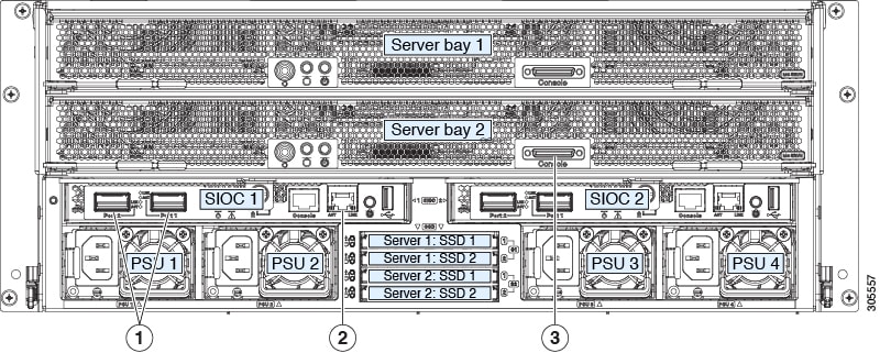
Figure 3. Figure E-3 Rear Panel Connectors for Setup

1

40-Gb QSFP ports (two on each SIOC)

3

KVM console connector on each server node

2

10/100/1000 dedicated management port

-

-

Step 6

Reconnect power cables to the system. Wait for approximately five minutes to allow the system to boot up.

Step 7

Connect a KVM cable (Cisco PID N20-BKVM) to the KVM connector on the server node at the rear of the system (See Figure E-3). Connect a USB keyboard and a VGA monitor to the KVM cable.

Step 8

Open the Cisco IMC Configuration Utility:

  1. Press and hold the front panel power button for four seconds to boot the system. Watch the screen for the prompt to press F8.

  2. During bootup, press F8 when prompted to open the Cisco IMC Configuration Utility.

This utility has three windows that you can toggle between by pressing F1 or F2.

Step 9

The utility prompts you to change the default user password. Set a default user password before continuing.

Step 10

Set the CMCs in all SIOCs and the BMCs in all server nodes to the factory defaults.

The Factory Default check box has two options but you must perform two resets in this order:

  1. Select Chassis Controller Configuration and save your changes. Both CMCs in the SIOCs are set to the factory default state.

  2. Select Server Controller Configuration and save your changes. The server node is set back to its factory default state and the server/host reboots.

Note


The BMC reboots after resetting to defaults. Watch for the prompt to press F8 when the server reboots in the next step.

Note


Set the BMC in the second server node to factory defaults also.

Step 11

When prompted, press F8 to enter the Cisco IMC Configuration Utility again.

Step 12

Set a new Cisco IMC password when prompted.

Step 13

Configure the management, CMC, and BMC IP addresses for the system.

Note


If you use a DHCP server and you already have QSFP cables attached to the SIOC, the management IP address and network settings are already filled in. If you disable DHCP, you must set your own static management IP address and network settings.

Step 14

This step is only for setting static IPs (DHCP disabled)—Set the CMC and BMC internal IP addresses by using the Cisco IMC interface, as described in Setting Static CMC and BMC Internal IP Addresses.

Step 15

Use the Cisco IMC (GUI or CLI) to define hard drive zoning, which maps the hard drives to individual server nodes. Use either the Cisco IMC GUI or the Cisco IMC CLI:

Using the Cisco IMC GUI:

  1. Use the management IP address of the CMC in either SIOC to log in to the Cisco IMC management software.

  2. Navigate to the following tab:

    Chassis > Inventory > Dynamic Storage > Zoning

  3. Select the drives and then assign them to Server1 or Server2.

Using the Cisco IMC CLI, enter the following commands with your choices:

Server# scope chassis
Server /chassis# scope dynamic-storage
Server /chassis/dynamic-storage# assign-drive <server ID> <
drive-slotid-list> 

For example:

Server# scope chassis
Server /chassis # scope dynamic-storage
svbu-huu-sanity-col2-1-vcmc /chassis/dynamic-storage # assign-drive server2 27 
Are you sure you want to assign drives 27 to server2
Enter 'yes' to confirm -> yes
assign-drive operation successful.

Migrating From C3160 With One M3 Server Node to S3260 With One M4 Server Node

This procedure upgrades a Cisco UCS C3160 system that is using one C3X60 M3 server node to a Cisco UCS S3260 system that uses one C3X60 M4 server node.

Items Required For This Migration

Hardware

  • A Cisco UCS C3160 system with one M3 server node in server bay 1 (the upper bay). The system must be running Cisco IMC 2.0(8) or 2.0(9) firmware (only) before you can begin the migration.


    Note


    Migration to S3260 with M4 server nodes is supported only with chassis part-number versions 68-5286-06 and later. The motherboard in these chassis versions supports all M4 system components.


  • A new system I/O controller (SIOC), UCSC-S3260-SIOC. This new SIOC must be running Cisco IMC 2.0.13 or later firmware (the factory-installed default)

  • A new C3X60 M4 server node.

Software

  • Up to five IP addresses, either configured in your DHCP server or manually entered for static IP addresses. See System IP Addresses for more information.

  • The latest Host Upgrade Utility package for Cisco IMC 2.0(8) or 2.0(9) firmware. This is used to update the entire Cisco S3160 system with M3 nodes to the prerequisite firmware.

  • The Host Upgrade Utility package for Cisco IMC 2.0(13) or later firmware. This is used to upgrade the system to Cisco S3260 with M4 server node requirements.

    For instructions on downloading and using the utility, see the instructions in the guide for your

    release: HUU Guides

Upgrade Considerations

Note the following considerations:

  • After the upgrade, you must manually define drive zoning to map the hard drives to individual server nodes.

  • After the upgrade, your boot SSDs might lose their operating system. In this case, reinstall your operating system to the boot SSDs.

Migration Procedure

Procedure Summary

SUMMARY STEPS

    Procedure Summary
  1. Ensure that the entire C3160 system is running Cisco IMC 2.0(8) or 2.0(9).
  2. Upgrade the entire C3160 system to 2.0(13).
  3. Disconnect all power cords to remove power from the system.
  4. Replace the C3160 SIOCs with S3260 SIOCs (UCSC-S3260-SIOC).
  5. Replace the M3 server node with an M4 server node.
  6. Reconnect network cables and power cords
  7. Boot the system and set CMC and BMC to factory defaults.
  8. Configure IP addresses and network settings.
  9. Perform drive zoning for hard drives.

DETAILED STEPS

Procedure Summary
  Command or Action Purpose

Step 1

Ensure that the entire C3160 system is running Cisco IMC 2.0(8) or 2.0(9).

Step 2

Upgrade the entire C3160 system to 2.0(13).

Step 3

Disconnect all power cords to remove power from the system.

Step 4

Replace the C3160 SIOCs with S3260 SIOCs (UCSC-S3260-SIOC).

Step 5

Replace the M3 server node with an M4 server node.

Step 6

Reconnect network cables and power cords

Step 7

Boot the system and set CMC and BMC to factory defaults.

Step 8

Configure IP addresses and network settings.

Step 9

Perform drive zoning for hard drives.

Migrating From C3160 With One M3 Server Node to S3260 With One M4 Server Node

Procedure

Step 1

The entire Cisco C3160 system must be running Cisco IMC 2.0(8) or 2.0(9) before you can begin the migration.

Note


This might require upgrading your system firmware if you are running a release earlier than 2.0(8).

If the system is running an earlier version, download and run the C3160 Host Upgrade Utility (HUU) for release 2.0(8) or 2.0(9). Use the Host Upgrade Utility User Guide for release 2.0(8) or 2.0(9) or later for instructions on downloading and using the utility: HUU Guides

Step 2

Use the C3160 HUU for 2.0(13) to upgrade the entire system to Cisco IMC release 2.0(13).

Step 3

Shut down and remove power from the entire system. You must disconnect all power cords to completely remove power.

Step 4

Remove all existing C3160 SIOCs from the system.

Step 5

Install one new S3260 SIOC (UCSC-S3260-SIOC=) into SIOC bay 1 (the left bay as you face the rear of the server, as shown in Figure E-4).

Step 6

Remove the existing M3 server node and replace it with a new M4 server node in either server bay.

If your M4 server node has an I/O expander attached to its top, install them together with the server node in server bay 2.

See Replacing a Server Node, for instructions.

Step 7

Attach your networking cables to the new SIOC ports as desired.

Step 8

Connect a keyboard and monitor to the system:

  1. Connect a KVM cable (Cisco PID N20-BKVM) to the external KVM connector on the server node at the rear of the system (see Figure E-4 for the connector location).

  2. Connect a VGA monitor and a USB keyboard to the connectors on the KVM cable.

Figure 4. Figure E-4 Rear Panel Connectors for Setup

1

40-Gb QSFP ports (two on each SIOC)

3

KVM console connector on each server node

2

10/100/1000 dedicated management port

-

-

Step 9

Connect power cords and then power on the system. Watch for the prompt to press F8.

Step 10

When prompted, press F8 to enter the Cisco IMC Configuration Utility.

This utility has three windows that you can toggle between by pressing F1 or F2.

Step 11

The utility prompts you to change the default user password. Set a default user password before continuing.

Step 12

Set the CMC in the SIOC and the BMC in the server node to the factory defaults.

The Factory Default check box has two options:

  • Chassis Controller Configuration: Both CMCs in the SIOCs are set to the factory default state.

  • Server Controller Configuration: the server node is set back to its factory default state and the server/host reboots.

Note


The BMC and the CMC reboot after resetting to defaults. Wait for the reboot to complete before continuing with the next step.

When the reboot finishes, the system is operating as a S3260 chassis.

Step 13

When prompted, press F8 to enter the Cisco IMC Configuration Utility.

Step 14

Configure the networking properties for your desired IP addresses, NIC mode, and NIC redundancy.

  1. Be aware of the S3260 system requirement to set as many as five IP addresses. See System IP Addresses, for more information.

    At this point in the procedure, the system requires three addresses:

    • One management IP address

    • One CMC address for the SIOC

    • One BMC address for the server node

    Note


    If you use a DHCP server, the addresses are defined by the DHCP server. If you disable DHCP, you must set your own static management IP addresses and network settings.

  2. Make networking settings using the Cisco IMC Configuration Utility, which you opened by pressing F8 during boot. See Setting Up the System Using the Cisco IMC Configuration Utility.

  3. If you want to set static IP addresses for the CMC and BMC controllers, you will be directed to use the Cisco IMC management interface as described in Setting Static CMC and BMC Internal IP Addresses.

Step 15

Optional—At this point, you can install a second server node and a second SIOC to the Cisco S3260 chassis. See Installing a Second Server Node or SIOC to the S3260 System With M4 Server Nodes.


Installing a Second Server Node or SIOC to the S3260 System With M4 Server Nodes

Installing a Second SIOC

It is important that the CMC firmware in the new S3260 SIOC is the same version as the CMC firmware in the existing SIOC. If the CMC versions are different, you must upgrade them to match.


Note


When the second SIOC is inserted, its chassis management controller (CMC) becomes the standby CMC. If you move a S3260 SIOC from one chassis to another, the SIOC’s CMC configuration is treated as incompatible and is automatically deleted. The new SIOC CMC will sync with the active CMC in the existing SIOC.


SUMMARY STEPS

  1. A second S3260 SIOC can be installed without removing system power:
  2. Attach QSFP cabled to the QSFP ports on the second SIOC.
  3. Assign a CMC IP address to the new SIOC:
  4. Verify that the CMC and adapter firmware in the SIOC matches the firmware in the other SIOC. If they do not match, update the firmware in the SIOCs.

DETAILED STEPS

  Command or Action Purpose

Step 1

A second S3260 SIOC can be installed without removing system power:

Step 2

Attach QSFP cabled to the QSFP ports on the second SIOC.

Note


Note If you are using the Dedicated NIC mode, connect an RJ-45 Ethernet cable to the dedicated management port.

Step 3

Assign a CMC IP address to the new SIOC:

  • If the S3260 system has been configured to use your DHCP server, allow it to assign the CMC IP address to the new SIOC.

  • If you are not using a DHCP server, use the Cisco IMC interface (CLI or GUI) to manually assign a CMC IP address for the new SIOC, as described in Setting Up the System Using the Cisco IMC Configuration Utility.

Step 4

Verify that the CMC and adapter firmware in the SIOC matches the firmware in the other SIOC. If they do not match, update the firmware in the SIOCs.

Installing a Second M4 Server Node

Items Required For This Procedure

  • An M5 server node running Cisco IMC 3.1(3x) or later firmware.

Procedure

SUMMARY STEPS

  1. Verify that the target S3260 system is running Cisco IMC 3.1(3x) or later firmware.
  2. A second server node can be installed without removing system power:
  3. Verify that the server node is manageable from the S3260 Cisco IMC CLI or GUI. If the new server is not displayed in the CLI or GUI, then you must reset the server to factory defaults.
  4. Assign a BMC IP address to the new server node:

DETAILED STEPS

  Command or Action Purpose

Step 1

Verify that the target S3260 system is running Cisco IMC 3.1(3x) or later firmware.

Step 2

A second server node can be installed without removing system power:

  1. If you have a drive expander module or I/O expander in the system, remove it from the system.

    • To remove a drive expander module, see Replacing a Disk Expansion Tray, page 3-27.

    • To remove an I/O expander, you must remove the server node and then detach the I/O expander from it. See Replacing an I/O Expander (C3X60 M4 or S3260 M5 Server Nodes Only), page 3-37.

  2. With the two ejector levers open, align the new server node with the empty bay.

  3. Push the server node into the bay until it engages with the midplane connectors and is flush with the chassis surface.

  4. Rotate both ejector levers toward the center until they lay flat and their latches lock into the rear of the server node.

Step 3

Verify that the server node is manageable from the S3260 Cisco IMC CLI or GUI. If the new server is not displayed in the CLI or GUI, then you must reset the server to factory defaults.

For example using the CLI:

S3260-Server# scope chassis
S3260-Server /chassis# show server
<Server ID> <Power state> <Serial number> <Product name> <PID> <UUID> 
------------------------------------------------------
1 on FCH1848793G UCS S3260 UCSC-C3K-M4SRB 36399C1B-6E9A-4E95-BEAC-B9003DCA6C7F
2 on FCH18407MY2 UCS S3260 UCSC-C3K-M4SRB C00E5CEO-A596-45E0-82CD-0B2F0A395FAC
  • If the server is displayed in the CLI or GUI, go to the next step.

  • If the server is not displayed, set it to factory defaults as descried in the following steps:

    1. Use a KVM cable to attach a monitor and keyboard to the KVM connector on the rear of the server that you just inserted.

    2. Boot the server node and when prompted, press F8 to enter the Cisco IMC Configuration Utility.

    3. Press F1 to go to the second screen of the utility.

    4. Select the Factory Default option for Server Controller Configuration. The selected server node is set back to its factory default state and the selected server/host reboots.

    5. Press F10 to save changes to reboot the server’s BMC.

    6. Wait for the reboot to complete (approximately five minutes).

Step 4

Assign a BMC IP address to the new server node:

  • If the S3260 system has been configured to use your DHCP server, allow it to assign the BMC IP address to the new server node then go to the next step.

  • If you are not using a DHCP server, use the Cisco IMC interface (CLI or GUI) to manually assign a BMC IP address for the new server node.

    For example using the CLI:

    S3260-Server# scope network
    S3260-Server /cimc/network# set v4-addr-bmc<n> <v4 ip-address> 
    S3260-Server /cimc/network# set v6-addr-bmc<n> <v6 ip-address> 

    For more information see Cisco UCS C-Series Integrated Management Controller GUI Configuration Guide for S3260 Servers or the Cisco UCS C-Series Integrated Management Controller CLI Configuration Guide for S3260 Servers here: Configuration Guides.

    The second M5 server node is now ready for use in the S3260 system.