Overview

This chapter contains the following topics:

Overview

The Cisco UCS C245 M8 (UCSC-C245-M8) server is a two rack unit (2RU) rack server featuring 4th Gen AMD EPYC™ CPUs and 5th Gen AMD EPYC CPUs. A maximum of 160 cores per CPU is supported for a total of up to 320 cores per dual-CPU server.

Figure 1. Cisco UCS C245 M8 Server (With Locking Front Bezel)
Figure 2. Cisco UCS C245 M8 Server (Without Locking Front Bezel)

Each server supports the following:

  • Memory: Up to twenty four 256GB DDR5 DIMMs. Twelve DIMMs are supported per CPU socket for a total server capacity of 6TB of 256 GB DIMMs with 4th Gen AMD EPYC™ Processors (up to 4800MT/s DDR5 memory) or up to twenty four 256GB DDR5 DIMMs (up to 6000MT/s DDR5 memory) with 5th Gen AMD EPYC™ .

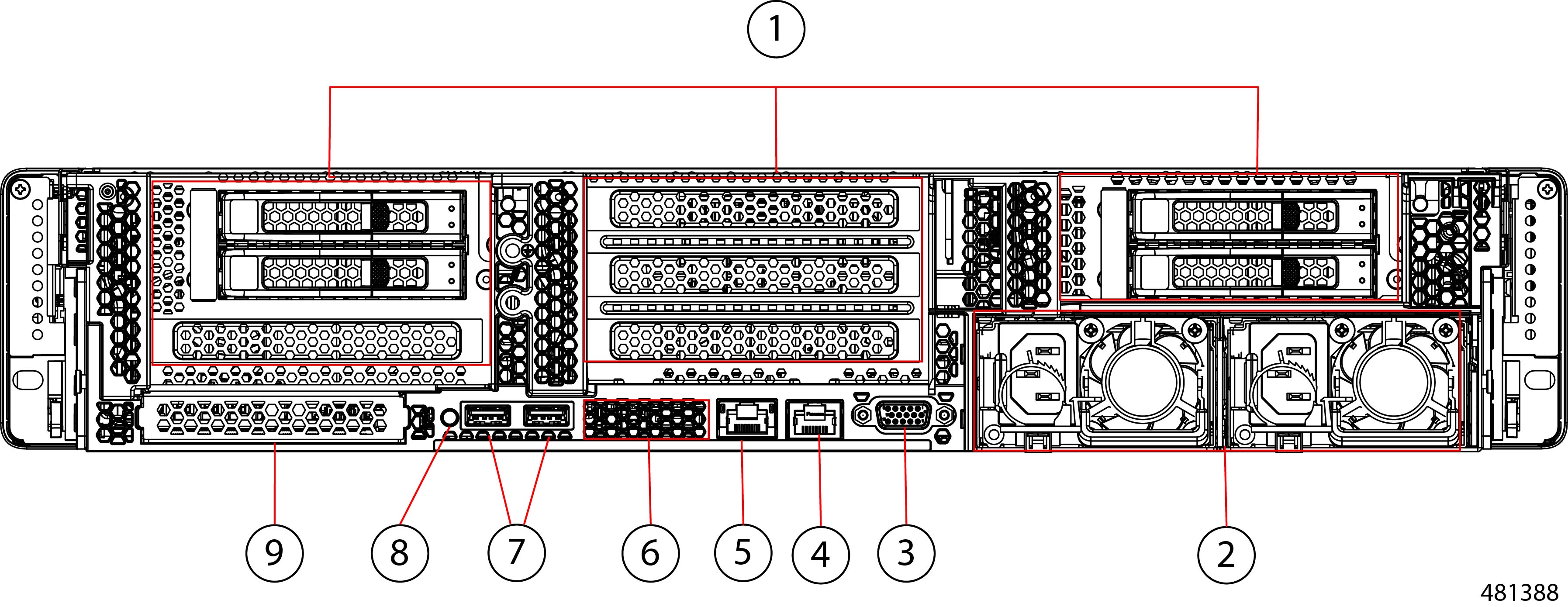
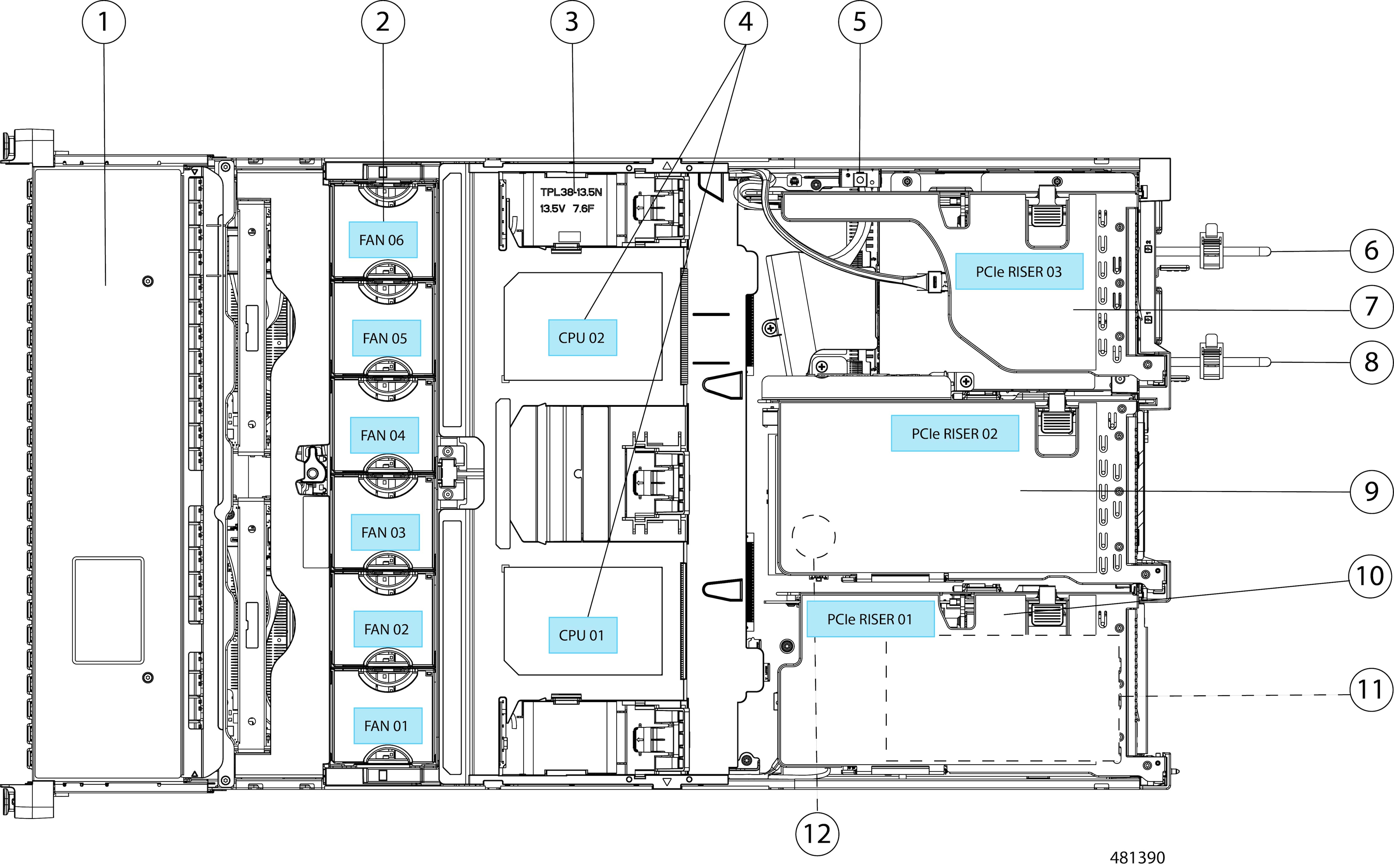
  • PCIe support: Up to eight PCIe Gen 4.0 slots or up to four PCIe Gen 5.0 slots , plus a hybrid modular LAN on motherboard (mLOM) /OCP 3.0 slot and 1 dedicated 24-Gbps RAID controller slot.

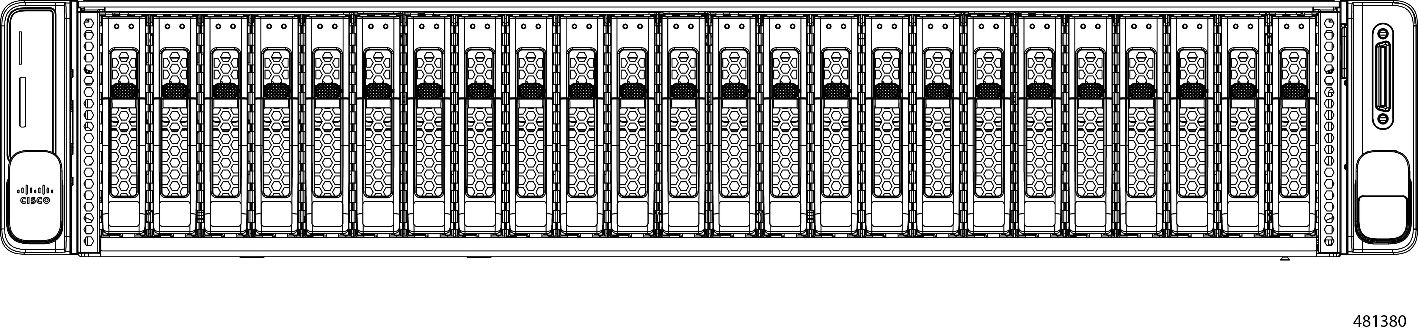
  • Drive Support: Up to 28 hot-swappable small-form-factor (SFF) SAS/SATA or NVMe drives (with up to 8 direct-attach NVMe drives)

    • Front-loading drive bays 1—24 support 2.5-inch SAS/SATA or U.3 NVMe drives.

    • Optionally, front-loading drive bays 1 to 4 support direct-attached 2.5-inch NVMe SSDs (with optional front NVMe cables).

    • Optionally, Risers 1B and 3D support up to four Gen4 NVMe SSDs or four Gen4 SAS/SATA SSDs (2 drives per riser).

  • Storage Controllers, RAID and HBA:

    • The Cisco 24G Tri-mode RAID controller:

      • RAID support (RAID 0, 1, 5, 6, 10, 50, 60, RAID0, and RAID00)

      • UCSC-RAID-MP1L32 supports 32 drives

      • UCSC-RAID-M1L16 - support 16 drives (14 drives with one controller and 28 drives with 2 controllers).

      • UCSC-HBA-M1L16 - supports 16 drives (14 drives with one controller and 28 drives with 2 controllers).

      • UCSC-RAID-HP - supports 16 drives (14 drives with one controller and 28 drives with 2 controllers).

    • Cisco 12G 9500-8e 12G SAS HBA for external JBOD attach

  • M.2 boot optimized drives:

    • Up to two 960GB SATA M.2 drives with hardware RAID support

    • Up to two 960GB NVMe M.2 drives with NVMe hardware RAID

  • Support for up to eight GPUs

  • Network connectivity: Modular LOM or OCP 3.0 card

    • One dedicated PCIe Gen4x16 slot that can be used to add an mLOM or OCP 3.0 card for additional rear-panel connectivity

    • mLOM slot that can be used to install a Cisco UCS Virtual Interface Card (VIC) without consuming a PCIe slot, supporting quad-port 10/25/50 Gbps or dual-port 40/100/200 Gbps network connectivity

    • OCP 3.0 slot that features full out-of-band management for a set of supported adapters

  • Up to three rear PCIe Riser combinations support a wide variety of GPU and HDD options. See Riser Options.

  • Network connectivity through either a dedicated modular LAN over motherboard card (mLOM) that accepts a series 15xxx Cisco virtual interface card (VIC) or a third-party NIC.

    • Or, one mLOM/VIC card that provides 10/25/40/50/100 Gbps. The following mLOMs are supported:

      • Cisco UCS VIC 15427 Quad Port CNA MLOM (UCSC-M-V5Q50GV2) supports:

        • a x16 PCIe Gen4 Host Interface to the rack server

        • four 10G/25G/50G SFP+/SFP28/SFP56 ports

        • 4GB DDR4 Memory, 3200 MHz

        • Integrated blower for optimal ventilation

        • Secure boot support

      • Cisco UCS VIC 15425 Quad Port 10G/25G/50G SFP56 CNA PCIe (UCSC-P-V5Q50G)

        • a x16 PCIe Gen4 Host Interface to the rack server

        • Four 10G/25G/50G SFP+/SFP28/SFP56 ports

        • 4GB DDR4 Memory, 3200MHz

        • Integrated blower for optimal ventilation

        • Secure boot support

      • Cisco UCS VIC 15237 Dual Port 40G/100G/200G QSFP56 mLOM (UCSC-M-V5D200GV2) supports:

        • a x16 PCIe Gen4 Host Interface to the rack server

        • two 40G/100G/200G QSFP/QSFP28/QSFP56 ports

        • 4GB DDR4 Memory, 3200 MHz

        • Integrated blower for optimal ventilation

        • Secure boot support

      • Cisco UCS VIC 15235 Dual Port 40G/100G/200G QSFP56 CNA PCIe (UCSC-P-V5D200G)

        • a x16 PCIe Gen4 Host Interface to the rack server

        • two 40G/100G/200G QSFP/QSFP28/QSFP56 ports

        • 4GB DDR4 Memory, 3200MHz

        • Integrated blower for optimal ventilation

        • Secure boot support

  • Server configuration and management is supported through Cisco UCS Manager (UCSM), version 4.3(2) or later.

The Cisco UCS C245 M8 (UCSC-C245-M8SX) server is also available as GPU Ready Configuration unit. The server is configured to accept GPU, but GPUs are not installed while placing the order.

GPU Ready Configuration units are shipped with low profile heatsink: UCSC-HSLP-C245M8 and UCSC-GPUAD-245M8 (GPU air duct).


Note


GPU Ready Configuration should follow the same temperature limit as GPU configured unit.

You should select the GPU air duct PID to enable GPU Ready Configuration. Follow Cisco Commerce Workspace (CCW) rules for more details.


External Features

This topic shows the external features of the server.

Cisco UCS C245 M8 (SFF Drives, 24-Drive) Front Panel Features

The following figure shows the front panel features of the server:

Figure 3. Cisco UCS C245 M8 (SFF Drives, 24-Drive) Front Panel

The Cisco UCS C245 M8 server features drive bays 1 to 24, which support SAS/SATA drives. Drive bays are numbered 1 through 24 from left to right. Optionally, front-loading drive bays 1 to 4 support 2.5-inch NVMe SSDs (with optional front NVMe cables). Other features are:

1

SAS/SATA drive fault LED

2

SAS/SATA drive activity LED

3

Power button/power status LED

4

Unit identification button/LED

5

System Status LED

6

Fan status LED

7

Temperature status LED

8

Power supply status LED

9

Network link activity LED

Cisco UCS C245 M8 Rear Panel Features

The following configuration of the server has no additional storage installed, with possible combinations explained in table.

Figure 4. Cisco UCS C245 M8 Rear Panel

1

The Cisco UCS C245 M8 server supports three risers numbered 1 to 3 from left to right.

Riser 1—Supports Riser 1A, 1B, and 1C. PCIe slots 1, 2, and 3 are numbered bottom to top.

Riser 2—Supports Riser 2A and 2C. PCIe slots 4, 5, and 6 are numbered bottom to top.

Riser 3—Supports Riser 3A, 3B, 3C, and 3D. PCIe slots 7 and 8 are numbered bottom to top.

For more information, see Riser Options.

2

Power supplies (two, redundant as 1+1)

See Power Specifications for specifications and supported options.

3

VGA video port (DB-15 connector)

4

Serial port (RJ-45 connector) COM 1, BMC or Host Serial access

5

RJ45 BMC Dedicated Management Port

6

USB 3.0 ports, 2

7

Rear unit identification button/LED

8

Modular LAN-on-motherboard (mLOM) card slot (x16)

Riser Options

The server supports the following rear riser options.

  • Riser 1—Supports Riser 1A, 1B, and 1C. PCIe slots 1, 2, and 3 are numbered bottom to top with the following options:

    • Riser 1A (UCSC-RIS1A-240M6)—Slot 1 PCIe supports full height, ¾ length PCIe Gen4 add-in-card; Slot 2 PCIe supports full height, full length PCIe Gen4 Add-in-card. This slot can accept a double-wide GPU; Slot 3 PCIe supports full height, full length PCIe Add-in-card.

    • Riser 1B, Storage Option (UCSC-RIS1B-245M8)—Slot 1 PCIe is not present; Slot 2 (enumerated as slot 101) supports 2.5-inch Universal HDDs; Slot 3 (enumerated as slot 102) supports 2.5-inch Universal HDD. Both slots support a maximum of ither two Controller attached SAS/SATA/U.3 drives or CPU Direct Attached PCIe Gen4 x4 U.3/U.2 drives.

    • Riser 1C (UCSC-RIS1C-245M8)—Slot 1 PCIe supports full height, ¾ length PCIe Gen5 add-in-card; Slot 2 PCIe supports full height, full length PCIe Gen5 add-in-card. This slot can accept a double-wide GPU

  • Riser 2—Supports Riser 2A and 2C. PCIe slots 4, 5, and 6 are numbered bottom to top with the following options:

    • Riser 2A (UCSC-RIS2A-240M6)—Slot 4: PCIe support full height, ¾ length PCIe Gen4 add-in-card; Slot 5 and Slot 6: PCIe support full height, full length PCIe Gen4 add-in-card. Slot 5 can support a double-wide GPU up to 300W.

    • Riser 2C (UCSC-RIS2C-245M8)—Slot 4: PCIe support full height, ¾ length PCIe Gen5 add-in-card; Slot 5 PCIe support full height, full length PCIe Gen5 add-in-card. Slot 5 can support a double-wide GPU up to 300W.

  • Riser 3—Supports Riser 3A, 3B, 3C, and 3D. PCIe slots 7 and 8 are numbered bottom to top with the following options:

    • Riser 3A (UCSC-RIS3A-240M8)—Slot 7 PCIe supports full height, full length PCIe Gen4 add-in-card; Slot 8 PCIe supports full height, full length PCIe Gen4 add-in-card. Slots 7 and 8 are electrically x8 and x8 lanes.

    • Riser 3B (UCSC-RIS3B-240M8), Storage Option—Slot 7 (enumerated as slot 103) supports 2.5-inch Universal HDD; Slot 8 (enumerated as slot 104) supports 2.5-inch Universal HDD. Both slots support a maximum of either 2 SAS/SATA PCIe SAS4 or 2 NVMe PCIe Gen 4 x4 drives.

    • Riser 3C (UCSC-RIS3C-240M8)—Slot 7 PCIe supports full height, full length PCIe Gen4 add-in-card, which can accept a double-wide GPU; Slot 8 PCIe is not present. Slot 7 can support a double-wide GPU up to 300W.

    • Riser 3D, Storage Option (UCSC-RIS3D-240M8)—Slot 7 (enumerated as slot 103) supports 2.5-inch Universal HDD; Slot 8 (enumerated as slot 104) supports 2.5-inch Universal HDD. Both slots support a maximum of either two Controller attached SAS/SATA/U.3 drives or CPU Direct Attached PCIe Gen4 x4 U.3/U.2 drives.

Component Locations

This topic shows the locations of the field-replaceable components and service-related items. The view in the following figure shows the server with the top cover removed.

Figure 5. Cisco UCS C245 M8 Serviceable Component Locations

1

Front-loading drive bays.

2

Cooling fan modules (six, hot-swappable)

3

DIMM sockets on motherboard (12 per CPU)

See DIMM Population Rules and Memory Performance Guidelines for DIMM slot numbering.

Note


An air baffle rests on top of the DIMM and CPUs when the server is operating. The air baffle is not displayed in this illustration.

4

CPU sockets, 2

CPU sockets are arranged side by side and labeled CPU1 and CPU2 next to the CPU socket.

5

Chassis Intrusion Switch

6

Power Supply Unit (PSU) 1

Power supplies (hot-swappable when redundant as 1+1)

7

Riser 3—Supports Riser 3A, 3B, 3C, and 3D. PCIe slots 7 and 8 are contained in these risers. PCIe slots 7 and 8 are numbered bottom to top.

For information about risers, see Riser Options.

8

Power Supply Unit (PSU) 2

Power supplies (hot-swappable when redundant as 1+1)

9

Riser 2—Supports Riser 2A and 2C. PCIe slots 4, 5, and 6 are contained in these risers. PCIe slots 4, 5, and 6 are numbered bottom to top.

For information about risers, see Riser Options.

10

Riser 1—Supports Riser 1A, 1B, and 1C. PCIe slots 1, 2, and 3 are contained in these risers. PCIe slots 1, 2, and 3 are numbered bottom to top.

For information about risers, see Riser Options.

11

Optional mLOM/VIC/OCP 3.0 slot below Riser 1.

12

RTC Battery below Riser 2.

Summary of Server Features

The following table lists a summary of server features.

Table 1. Feature Summary

Feature

Description

Chassis

Two rack-unit (2RU) chassis

Processor

AMD 4th Gen EPYC Dual Socket (9004, 9004 with 3D V-cache® technology, and 97x4)

AMD 5th Gen EPYC Dual Socket (9005 with 3D V-cache® technology, and 97x4

Memory

5600MT/s DIMMs operating at 4800MT/s for AMD 4th Gen EPYC and 6400MT/s DIMMs operating at 6000MT/s for AMD 5th Gen EPYC sockets on the motherboard (Total 24 DIMMs with each CPU having 12 channels, 12 DIMMs)

Baseboard management

BMC, running Cisco Integrated Management Controller (Cisco IMC) firmware.

10/100/1000base-T interface connect to RJ45 connector as CIMC management port.

Network and management I/O

Rear panel:

  • 1-Gb Ethernet dedicated management port, 1

  • One RS-232 serial port (RJ-45 connector)

  • One VGA video connector port (DB-15 connector)

  • Two USB 3.0 ports

Front panel:

  • One front-panel keyboard/video/mouse (KVM) connector that is used with the KVM cable, which provides two USB 2.0, one VGA, and one DB-9 serial connector.

Modular LOM

x16 PCI Express Gen 4 connection, a SMBus (I2C), a 100M-Base-T link (MDI) interface and an RMII based NC-SI interface that support one wire Ethernetconnection to the host.

The panel interfaces support up to four 10/25/40/50/100Gb ports with RJ45 connectors or SFP+ interfaces

Power

Two power supplies, configurable either as redundant (as 1+1) or non-redundant (2+0)

  • 1050W DC PSU

  • 1200W AC PSU

  • 1600W AC PSU

  • 2300W AC PSU

Cooling

Six hot-swappable fan modules for front-to-rear cooling.

PCIe I/O

Eight horizontal PCIe expansion slots on 3 PCIe riser assemblies.

Two Storage PCIe slots for Cisco Storage Card.

One mLOM PCIe slot for Cisco Network Interface Card and OCP adapter

See PCIe Slot Specifications, on page 84 for specifications of the slots.

Storage, front-panel

Server is orderable in one Small form-factor (SFF) drives version, with 24-drive back-plane front panel configuration:

  • Front-loading drive bays 1—24 support 2.5-inch SAS/SATA or U.3 NVMe drives.

  • Optionally, front-loading drive bays 1 to 4 support direct-attached 2.5-inch NVMe SSDs (with optional front NVMe cables).

SAS/SATA drives are hot-swappable. NVMe SSDs are hot-pluggable, meaning that they must be shut down in the operating system before hot-removal.

Storage, rear-panel

Riser 1B—Slot 1 PCIe is disabled; Slot 2 supports 2.5-inch U.3 NVMe SSD; Slot 3 supports 2.5-inch SAS/SATA/NVMe SSD.

Riser 3D —Slot 7 supports 2.5-inch SAS/SATA/NVMe SSD; Slot 8 supports 2.5-inch SAS/SATA/NVMe SSD.

Storage, internal

  • Mini-storage module socket, optionally with either:

    • Dual M.2 2280 NVMe drives through the Cisco M.2 NVMe BOOT RAID Controller (UCS-M2-NVRAID). This component is plugged into a standard PCIe slot

    • Dual M.2 2280 SATA drive with hardware RAID through the Cisco Boot optimized M.2 RAID Controller (UCS-M2-HWRAID)

Storage Controllers, internal and external

RAID: Cisco 24G Tri-mode RAID controller supports up to 14 internal SAS/SATA/U.3 NVMe drives. This internal storage controller has Supercap backup and 4GB of flash-back write cache (FBWC). RAID levels 0, 1, 5, 6, 10, 50, 60, RAID0, and RAID00 are supported. JBOD, mixed JBOD, and mixed RAID modes are also supported.

JBOD: 9500 Series PCIe Gen 4.0 Tri-Mode Storage HBA 12Gb/s SAS/SATA/PCIe (NVMe). This HBA controller controls external storage devices and plugs into one of the server's PCIe slots.

RAID backup

The server has mounting brackets on the removable air baffle for two SuperCap units that are used with the two Cisco modular RAID controller cards.

GPU Support

Riser 1A—Slot 1 PCIe supports full height, ¾ length PCIe Gen4 add-in-card; Slot 2 PCIe supports full height, full length PCIe Gen4 add-in-card. This slot can support a double-wide GPU; Slot 3 PCIe supports full height, full length PCIe Gen4 add-in-card.

Riser 1C—Slot 1 PCIe supports full height, ¾ length PCIe Gen5 add-in-card; Slot 2 PCIe supports full height, full length PCIe Gen 5 add-in-card. This slot can support a double-wide GPU.

Riser 2A—Slot 4: PCIe support full height, ¾ length PCIe Gen4 add-in-card; Slot 5 and Slot 6: PCIe support full height, full length PCIe Gen4 add-in-card. Slot 5 can support a double-wide GPU.

Riser 2C—Slot 4: PCIe support full height, ¾ length PCIe Gen4 add-in-card; Slot 5 and Slot 6: PCIe support full height, full length PCIe Gen4 add-in-card. Slot 5 can support a double-wide GPU.

Riser 3A—Slot 7 PCIe supports full height, full length PCIe Gen4 add-in-card. This slot can support some double-wide GPUs. Slot 8 PCIe supports full height, full length PCIe Add-in-card.

Riser 3C—Slot 7 PCIe supports full height, full length PCIe Gen4 add-in-card.

Integrated video

Integrated VGA video.