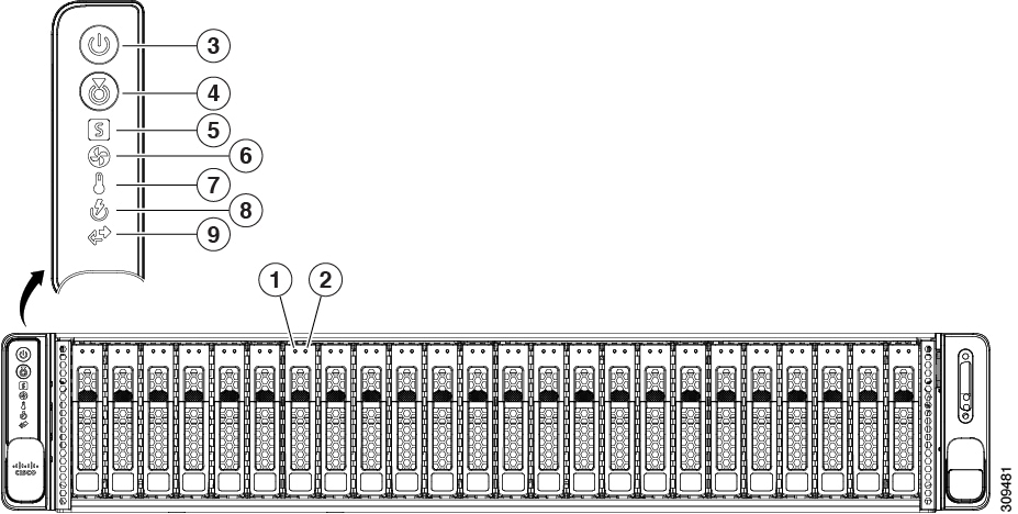
Maintaining the Server

This chapter contains the following topics:

Status LEDs and Buttons

Front-Panel LEDs

Figure 1. Front Panel LEDs
Table 1. Front Panel LEDs, Definition of States

LED Name

States

1

SAS

SAS/SATA drive fault

Note

 
NVMe solid state drive (SSD) drive tray LEDs have different behavior than SAS/SATA drive trays.
  • Off—The hard drive is operating properly.

  • Amber—Drive fault detected.

  • Amber, blinking—The device is rebuilding.

  • Amber, blinking with one-second interval—Drive locate function activated in the software.

2

SAS

SAS/SATA drive activity LED

  • Off—There is no hard drive in the hard drive tray (no access, no fault).

  • Green—The hard drive is ready.

  • Green, blinking—The hard drive is reading or writing data.

1

NVMe

NVMe SSD drive fault

Note

 
NVMe solid state drive (SSD) drive tray LEDs have different behavior than SAS/SATA drive trays.
  • Off—The drive is not in use and can be safely removed.

  • Green—The drive is in use and functioning properly.

  • Green, blinking—the driver is initializing following insertion or the driver is unloading following an eject command.

  • Amber—The drive has failed.

  • Amber, blinking—A drive Locate command has been issued in the software.

2

NVMe

NVMe SSD activity

  • Off—No drive activity.

  • Green, blinking—There is drive activity.

3

Power button/LED

  • Off—There is no AC power to the server.

  • Amber—The server is in standby power mode. Power is supplied only to the Cisco IMC and some motherboard functions.

  • Green—The server is in main power mode. Power is supplied to all server components.

4

Unit identification

  • Off—The unit identification function is not in use.

  • Blue, blinking—The unit identification function is activated.

5

System health

  • Green—The server is running in normal operating condition.

  • Green, blinking—The server is performing system initialization and memory check.

  • Amber, steady—The server is in a degraded operational state (minor fault). For example:

    • Power supply redundancy is lost.

    • CPUs are mismatched.

    • At least one CPU is faulty.

    • At least one DIMM is faulty.

    • At least one drive in a RAID configuration failed.

  • Amber, 2 blinks—There is a major fault with the system board.

  • Amber, 3 blinks—There is a major fault with the memory DIMMs.

  • Amber, 4 blinks—There is a major fault with the CPUs.

6

Fan status

  • Green—All fan modules are operating properly.

  • Amber, blinking—One or more fan modules breached the non-recoverable threshold.

7

Temperature status

  • Green—The server is operating at normal temperature.

  • Amber, steady—One or more temperature sensors breached the critical threshold.

  • Amber, blinking—One or more temperature sensors breached the non-recoverable threshold.

8

Power supply status

  • Green—All power supplies are operating normally.

  • Amber, steady—One or more power supplies are in a degraded operational state.

  • Amber, blinking—One or more power supplies are in a critical fault state.

9

Network link activity

  • Off—Cisco MLOM/VIC and BMC port link is idle.

  • Green—One or more Cisco MLOM/VIC and BMC port link are active, but there is no activity.

  • Green, blinking—One or more Cisco MLOM/VIC and BMC port link are active, with activity.

Rear-Panel LEDs

Figure 2. Rear Panel LEDs
Table 2. Rear Panel LEDs, Definition of States

LED Name

States

1

Unit Identification LED

  • Off—The unit identification function is not in use.

  • Blue, blinking—The unit identification function is activated.

2

1-Gb Ethernet dedicated management link speed

  • Off—Link speed is 10 Mbps.

  • Amber—Link speed is 100 Mbps.

  • Green—Link speed is 1 Gbps.

3

1-Gb Ethernet dedicated management link status

  • Off—No link is present.

  • Green—Link is active.

  • Green, blinking—Traffic is present on the active link.

4

Power supply status (one LED each power supply unit)

AC power supplies:

  • Off—No AC input (12 V main power off, 12 V standby power off).

  • Green, blinking—12 V main power off; 12 V standby power on.

  • Green, solid—12 V main power on; 12 V standby power on.

  • Amber, blinking—Warning threshold detected but 12 V main power on.

  • Amber, solid—Critical error detected; 12 V main power off (for example, over-current, over-voltage, or over-temperature failure).

Internal Diagnostic LEDs

The server has internal fault LEDs for CPUs, DIMMs, and fan modules.

Figure 3. Internal Diagnostic LED Locations

1

Fan module fault LEDs (one on the top of each fan module)

  • Amber—Fan has a fault or is not fully seated.

  • Green—Fan is OK.

2

DIMM fault LEDs (one behind each DIMM socket on the motherboard)

These LEDs operate only when the server is in standby power mode.

  • Amber—DIMM has a fault.

  • Off—DIMM is OK.

3

CPU fault LEDs

These LEDs operate only when the server is in standby power mode.

  • Amber—CPU has a fault.

  • Off—CPU is OK.

-

Preparing For Component Installation

Required Equipment For Service Procedures

The following tools and equipment are used to perform the procedures in this chapter:

  • T-20 Torx driver (supplied with replacement CPUs for heatsink removal)

  • #1 Phillips-head screwdriver for M.2 SSD replacement.

  • #2 Phillips-head screwdriver for PCIe riser/PCIe card replacement.

  • ¼-inch (or equivalent) flat-head screwdriver (for TPM installation)

  • Electrostatic discharge (ESD) strap or other grounding equipment such as a grounded mat

Shutting Down and Removing Power From the Server

The server can run in either of two power modes:

  • Main power mode—Power is supplied to all server components and any operating system on your drives can run.

  • Standby power mode—Power is supplied only to the service processor and certain components. It is safe for the operating system and data to remove power cords from the server in this mode.


Caution


After a server is shut down to standby power, electric current is still present in the server. To completely remove power, you must disconnect all power cords from the power supplies in the server, as directed in the service procedures.

You can shut down the server by using the front-panel power button or the software management interfaces.


Shutting Down Using the Power Button

Procedure


Step 1

Check the color of the Power button/LED:

  • Amber—The server is already in standby mode and you can safely remove power.

  • Green—The server is in main power mode and must be shut down before you can safely remove power.

Step 2

Invoke either a graceful shutdown or a hard shutdown:

Caution

 
To avoid data loss or damage to your operating system, you should always invoke a graceful shutdown of the operating system.
  • Graceful shutdown—Press and release the Power button. The operating system performs a graceful shutdown and the server goes to standby mode, which is indicated by an amber Power button/LED.

  • Emergency shutdown—Press and hold the Power button for 4 seconds to force the main power off and immediately enter standby mode.

Step 3

If a service procedure instructs you to completely remove power from the server, disconnect all power cords from the power supplies in the server.


Shutting Down Using The Cisco IMC GUI

You must log in with user or admin privileges to perform this task.

Procedure


Step 1

In the Navigation pane, click the Server tab.

Step 2

On the Server tab, click Summary.

Step 3

In the Actions area, click Power Off Server.

Step 4

Click OK.

The operating system performs a graceful shutdown and the server goes to standby mode, which is indicated by an amber Power button/LED.

Step 5

If a service procedure instructs you to completely remove power from the server, disconnect all power cords from the power supplies in the server.


Shutting Down Using The Cisco IMC CLI

You must log in with user or admin privileges to perform this task.

Procedure


Step 1

At the server prompt, enter:

Example:

server# scope chassis

Step 2

At the chassis prompt, enter:

Example:

server/chassis# power shutdown

The operating system performs a graceful shutdown and the server goes to standby mode, which is indicated by an amber Power button/LED.

Step 3

If a service procedure instructs you to completely remove power from the server, disconnect all power cords from the power supplies in the server.


Removing the Server Top Cover

Procedure


Step 1

Remove the top cover:

  1. If the cover latch is locked, slide the lock sideways to unlock it.

    When the latch is unlocked, the handle pops up so that you can grasp it.

  2. Lift on the end of the latch so that it pivots vertically to 90 degrees.

  3. Simultaneously, slide the cover back and lift the top cover straight up from the server and set it aside.

Step 2

Replace the top cover:

  1. With the latch in the fully open position, place the cover on top of the server about one-half inch (1.27 cm) behind the lip of the front cover panel.

  2. Slide the cover forward until the latch makes contact.

  3. Press the latch down to the closed position. The cover is pushed forward to the closed position as you push down the latch.

  4. Lock the latch by sliding the lock button to sideways to the left.

    Locking the latch ensures that the server latch handle does not protrude when you install the blade.

Figure 4. Removing the Top Cover

1

Cover lock

2

Cover latch handle


Hot Swap vs Hot Plug

Some components can be removed and replaced without shutting down and removing power from the server. This type of replacement has two varieties: hot-swap and hot-plug.

  • Hot-swap replacement—You do not have to shut down the component in the software or operating system. This applies to the following components:

    • SAS/SATA hard drives

    • SAS/SATA solid state drives

    • Cooling fan modules

    • Power supplies (when redundant as 1+1)

  • Hot-plug replacement—You must take the component offline before removing it for the following component:

    • NVMe PCIe solid state drives

Removing and Replacing Components


Warning


Blank faceplates and cover panels serve three important functions: they prevent exposure to hazardous voltages and currents inside the chassis; they contain electromagnetic interference (EMI) that might disrupt other equipment; and they direct the flow of cooling air through the chassis. Do not operate the system unless all cards, faceplates, front covers, and rear covers are in place.

Statement 1029


Caution


When handling server components, handle them only by carrier edges and use an electrostatic discharge (ESD) wrist-strap or other grounding device to avoid damage.


Tip


You can press the unit identification button on the front panel or rear panel to turn on a flashing, blue unit identification LED on both the front and rear panels of the server. This button allows you to locate the specific server that you are servicing when you go to the opposite side of the rack. You can also activate these LEDs remotely by using the Cisco IMC interface.


Component Locations

This topic shows the locations of the field-replaceable components and service-related items. The view in the following figure shows the server with the top cover removed.

Figure 5. Cisco UCS C245 M8 Serviceable Component Locations

1

Front-loading drive bays.

2

Cooling fan modules (six, hot-swappable)

3

DIMM sockets on motherboard (12 per CPU)

See DIMM Population Rules and Memory Performance Guidelines for DIMM slot numbering.

Note


An air baffle rests on top of the DIMM and CPUs when the server is operating. The air baffle is not displayed in this illustration.

4

CPU sockets, 2

CPU sockets are arranged side by side and labeled CPU1 and CPU2 next to the CPU socket.

5

Chassis Intrusion Switch

6

Power Supply Unit (PSU) 1

Power supplies (hot-swappable when redundant as 1+1)

7

Riser 3—Supports Riser 3A, 3B, 3C, and 3D. PCIe slots 7 and 8 are contained in these risers. PCIe slots 7 and 8 are numbered bottom to top.

For information about risers, see Riser Options.

8

Power Supply Unit (PSU) 2

Power supplies (hot-swappable when redundant as 1+1)

9

Riser 2—Supports Riser 2A and 2C. PCIe slots 4, 5, and 6 are contained in these risers. PCIe slots 4, 5, and 6 are numbered bottom to top.

For information about risers, see Riser Options.

10

Riser 1—Supports Riser 1A, 1B, and 1C. PCIe slots 1, 2, and 3 are contained in these risers. PCIe slots 1, 2, and 3 are numbered bottom to top.

For information about risers, see Riser Options.

11

Optional mLOM/VIC/OCP 3.0 slot below Riser 1.

12

RTC Battery below Riser 2.

Replacing Front-Loading SAS/SATA Drives


Note


You do not have to shut down the server or drive to replace SAS/SATA hard drives or SSDs because they are hot-swappable.

Front-Loading SAS/SATA Drive Population Guidelines

The Cisco UCS C245 M8 Server (UCSC-C245-M8SX) is orderable in one Small form-factor (SFF) drives version, with 24-drive back-plane front panel configuration:

  • Front-loading drive bays 1—24 support 2.5-inch SAS/SATA drives.


Note


Front-loading drive bays 1 to 4 (shown below) are hybrid. Bays 1 to 4 support 2.5-inch NVMe SSDs (with optional front NVMe cables) as well as SAS/SATA drives.


Drive bay numbering is shown in the following figures.

Figure 6. Small Form-Factor Drive Bay Numbering

Observe these drive population guidelines for optimum performance:

  • When populating drives, add drives to the lowest-numbered bays first.

  • Keep an empty drive blanking tray in any unused bays to ensure proper airflow.

  • You can mix SAS/SATA hard drives and SAS/SATA SSDs in the same server. However, you cannot configure a logical volume (virtual drive) that contains a mix of hard drives and SSDs. That is, when you create a logical volume, it must contain all SAS/SATA hard drives or all SAS/SATA SSDs.

4K Sector Format SAS/SATA Drives Considerations

  • You must boot 4K sector format drives in UEFI mode, not legacy mode. See the procedures in this section.

  • Do not configure 4K sector format and 512-byte sector format drives as part of the same RAID volume.

  • For operating system support on 4K sector drives, see the interoperability matrix tool for your server: Hardware and Software Interoperability Matrix Tools

Setting Up UEFI Mode Booting in the Cisco IMC GUI

Procedure

Step 1

Use a web browser and the IP address of the server to log into the Cisco IMC GUI management interface.

Step 2

Navigate to Server > BIOS.

Step 3

Under Actions, click Configure BIOS.

Step 4

In the Configure BIOS Parameters dialog, select the Advanced tab.

Step 5

Go to the LOM and PCIe Slot Configuration section.

Step 6

Set the PCIe Slot: HBA Option ROM to UEFI Only.

Step 7

Click Save Changes. The dialog closes.

Step 8

Under BIOS Properties, set Configured Boot Order to UEFI.

Step 9

Under Actions, click Configure Boot Order.

Step 10

In the Configure Boot Order dialog, click Add Local HDD.

Step 11

In the Add Local HDD dialog, enter the information for the 4K sector format drive and make it first in the boot order.

Step 12

Save changes and reboot the server. The changes you made will be visible after the system reboots.


Replacing a Front-Loading SAS/SATA Drive


Note


You do not have to shut down the server or drive to replace SAS/SATA hard drives or SSDs because they are hot-swappable.

Follow this procedure to remove a SAS/SATA drive from a vertical drive bay.

Procedure

Step 1

Remove the drive that you are replacing or remove a blank drive tray from the front of the server:

  1. Press the release button on the face of the drive tray.

  2. Grasp and open the ejector lever and then pull the drive tray out of the slot.

  3. If you are replacing an existing drive, remove the four drive-tray screws that secure the drive to the tray and then lift the drive out of the tray.

Step 2

Install a new drive:

  1. Place a new drive in the empty drive tray and install the four drive-tray screws.

  2. With the ejector lever on the drive tray open, insert the drive tray into the empty drive bay.

  3. Push the tray into the slot until it touches the backplane, and then close the ejector lever to lock the drive in place.

Figure 7. Replacing a Drive in a Drive Tray

1

Ejector lever

3

Drive tray screws (two on each side)

2

Release button

4

Drive removed from drive tray


Basic Troubleshooting: Reseating a SAS/SATA Drive

Sometimes it is possible for a false positive UBAD error to occur on SAS/SATA HDDs installed in the server.

  • Only drives that are managed by the UCS MegaRAID controller are affected.

  • Drives can be affected regardless where they are installed in the server (front-loaded, rear-loaded, and so on).

  • Both SFF and LFF form factor drives can be affected.

  • Drives installed in all Cisco UCS C-Series servers with M3 processors and later can be affected.

  • Drives can be affected regardless of whether they are configured for hotplug or not.

  • The UBAD error is not always terminal, so the drive is not always defective or in need of repair or replacement. However, it is also possible that the error is terminal, and the drive will need replacement.

Before submitting the drive to the RMA process, it is a best practice to reseat the drive. If the false UBAD error exists, reseating the drive can clear it. If successful, reseating the drive reduces inconvenience, cost, and service interruption, and optimizes your server uptime.


Note


Reseat the drive only if a UBAD error occurs. Other errors are transient, and you should not attempt diagnostics and troubleshooting without the assistance of Cisco personnel. Contact Cisco TAC for assistance with other drive errors.


To reseat the drive, see Reseating a SAS/SATA Drive.

Reseating a SAS/SATA Drive

Sometimes, SAS/SATA drives can throw a false UBAD error, and reseating the drive can clear the error.

Use the following procedure to reseat the drive.


Caution


This procedure might require powering down the server. Powering down the server will cause a service interruption.


Before you begin

Before attempting this procedure, be aware of the following:

  • Before reseating the drive, it is a best practice to back up any data on it.

  • When reseating the drive, make sure to reuse the same drive bay.

    • Do not move the drive to a different slot.

    • Do not move the drive to a different server.

    • If you do not reuse the same slot, the Cisco management software (for example, Cisco IMM) might require a rescan/rediscovery of the server.

  • When reseating the drive, allow 20 seconds between removal and reinsertion.

Procedure

Step 1

Attempt a hot reseat of the affected drive(s). Choose the appropriate option:

  1. For a front-loading drive, see Replacing a Front-Loading SAS/SATA Drive.

Step 2

During boot up, watch the drive's LEDs to verify correct operation.

See Front-Panel LEDs and Rear-Panel LEDs.

Step 3

If the error persists, cold reseat the drive, which requires a server power down. Choose the appropriate option:

  1. Use your server management software to gracefully power down the server.

    See the appropriate Cisco management software documentation.

  2. If server power down through software is not available, you can power down the server by pressing the power button.

    See Front-Panel LEDs and Rear-Panel LEDs.

  3. Reseat the drive as documented in Step 1.

  4. When the drive is correctly reseated, restart the server, and check the drive LEDs for correct operation as documented in Step 2.

Step 4

If hot and cold reseating the drive (if necessary) does not clear the UBAD error, choose the appropriate option:

  1. Contact Cisco Systems for assistance with troubleshooting.

  2. Begin an RMA of the errored drive.


Replacing Front-Loading NVMe SSDs

This section is for replacing 2.5-inch form-factor NVMe solid-state drives (SSDs) in front-panel drive bays.

Front-Loading NVMe SSD Population Guidelines

The Cisco UCS C245 M8 Server (UCSC-C245-M8SX) supports 2.5 inch NVMe SSDs in the following front slots:

  • Front-loading drive bays 1 to 4 support 2.5-inch NVMe SSDs (with optional front NVMe cables).

Front-Loading NVME SSD Requirements and Restrictions

Observe these requirements:

  • The server must have two CPUs. PCIe riser 2 and 3 are not available in a single-CPU system.

  • PCIe cable (CBL-FNVME-C245M8). This is the cable that carries the PCIe signal from the front-panel drive backplane to PCIe riser 1B, 3B, or 3D.

  • Hot-plug support must be enabled in the system BIOS. If you ordered the system with NVMe drives, hot-plug support is enabled at the factory.

Observe these restrictions:

  • NVMe 2.5 SSDs support booting only in UEFI mode. Legacy boot is not supported. For instructions on setting up UEFI boot, see Setting Up UEFI Mode Booting in the Cisco IMC GUI.

  • You cannot control U.2 NVMe PCIe SSDs with a SAS RAID controller because NVMe SSDs interface with the server via the PCIe bus.

  • You can combine NVMe SSDs in the same system, but the same partner brand must be used. For example, two Intel NVMe SFF 2.5-inch SSDs and two HGST SSDs is an invalid configuration.

  • UEFI boot is supported in all supported operating systems.

Enabling Hot-Plug Support in the System BIOS

Hot-plug (OS-informed hot-insertion and hot-removal) is disabled in the system BIOS by default.

  • If the system was ordered with NVMe PCIe SSDs, the setting was enabled at the factory. No action is required.

  • If you are adding NVMe PCIe SSDs after-factory, you must enable hot-plug support in the BIOS. See the following procedures.

Enabling Hot-Plug Support Using the BIOS Setup Utility
Procedure

Step 1

Enter the BIOS setup utility by pressing the F2 key when prompted during bootup.

Step 2

Navigate to Advanced > PCI Subsystem Settings > NVMe SSD Hot-Plug Support.

Step 3

Set the value to Enabled.

Step 4

Save your changes and exit the utility.


Enabling Hot-Plug Support Using the Cisco IMC GUI
Procedure

Step 1

Use a browser to log in to the Cisco IMC GUI for the server.

Step 2

Navigate to Compute > BIOS > Advanced > PCI Configuration.

Step 3

Set NVME SSD Hot-Plug Support to Enabled.

Step 4

Save your changes.


Replacing a Front-Loading NVMe SSD

This topic describes how to replace 2.5- or form-factor NVMe SSDs in the front-panel drive bays.


Note


OS-surprise removal is not supported. OS-informed hot-insertion and hot-removal are supported on all supported operating systems.


Note


OS-informed hot-insertion and hot-removal must be enabled in the system BIOS. See Enabling Hot-Plug Support in the System BIOS.


Procedure

Step 1

Remove an existing front-loading NVMe SSD:

  1. Shut down the NVMe SSD to initiate an OS-informed removal. Use your operating system interface to shut down the drive, and then observe the drive-tray LED:

    • Green—The drive is in use and functioning properly. Do not remove.

    • Green, blinking—the driver is unloading following a shutdown command. Do not remove.

    • Off—The drive is not in use and can be safely removed.

  2. Press the release button on the face of the drive tray.

  3. Grasp and open the ejector lever and then pull the drive tray out of the slot.

  4. Remove the four drive tray screws that secure the SSD to the tray and then lift the SSD out of the tray.

Step 2

Install a new front-loading NVMe SSD:

  1. Place a new SSD in the empty drive tray and install the four drive-tray screws.

  2. With the ejector lever on the drive tray open, insert the drive tray into the empty drive bay.

  3. Push the tray into the slot until it touches the backplane, and then close the ejector lever to lock the drive in place.

Step 3

Observe the drive-tray LED and wait until it returns to solid green before accessing the drive:

  • Off—The drive is not in use.

  • Green, blinking—the driver is initializing following hot-plug insertion.

  • Green—The drive is in use and functioning properly.

Figure 8. Replacing a Drive in a Drive Tray

1

Ejector lever

3

Drive tray screws (two on each side)

2

Release button

4

Drive removed from drive tray


Replacing Rear-Loading NVMe SSDs

This section is for replacing 2.5-inch form-factor NVMe solid-state drives (SSDs) in rear-panel PCIe riser slots.

Rear-Loading NVMe SSD Population Guidelines

The Cisco UCS C245 M8 Server (UCSC-C245-M8SX) server supports NVMe SSDs in the following rear slots:

  • Riser 1—Supports PCIe slots 1, 2, and 3 which are numbered bottom to top with the following options:

    • Riser 1B (Storage Option)—Slot 1 PCIe is a standard PCIe slot and not intended for drives; Slot 2 supports 2.5-inch NVMe SSD; Slot 3 supports 2.5-inch NVMe SSD.

  • Riser 3—Supports Riser 3A, 3B or 3D. PCIe slots 7 and 8 numbered bottom to top with the following options:

    • Riser 3B and 3D—Slot 7 supports 2.5-inch NVMe SSD; Slot 8 supports 2.5-inch NVMe SSD.

Rear-Loading NVME SSD Requirements and Restrictions

Observe these requirements:

  • The server must have two CPUs to support all four NVMe SSDs.

  • PCIe riser 1B or 3D have connectors for the cable that connect to the front-panel drive controller.

  • Hot-plug support must be enabled in the system BIOS. If you ordered the system with NVMe drives, hot-plug support is enabled at the factory.

Observe these restrictions:

  • NVMe SSDs support booting only in UEFI mode. Legacy boot is not supported. For instructions on setting up UEFI boot, see Setting Up UEFI Mode Booting in the Cisco IMC GUI.

  • For U.2 NVMe, you cannot control U.2 NVMe PCIe SSDs with a SAS RAID controller because NVMe SSDs interface with the server through the PCIe bus.

  • You can combine NVMe 2.5-inch SSDs and HHHL form-factor SSDs in the same system, but the same partner brand must be used. For example, two Intel NVMe SFF 2.5-inch SSDs and two HGST HHHL form-factor SSDs is an invalid configuration. A valid configuration is two HGST NVMe SFF 2.5-inch SSDs and two HGST HHHL form-factor SSDs.

  • UEFI boot is supported in all supported operating systems.

Replacing a Rear-Loading NVMe SSD

This topic describes how to replace 2.5-inch form-factor NVMe SSDs in the rear-panel drive bays.


Note


OS-surprise removal is not supported. OS-informed hot-insertion and hot-removal are supported on all supported operating systems except VMware ESXi.


Note


OS-informed hot-insertion and hot-removal must be enabled in the system BIOS. See Enabling Hot-Plug Support in the System BIOS.


Procedure

Step 1

Remove an existing rear-loading NVMe SSD:

  1. Shut down the NVMe SSD to initiate an OS-informed removal. Use your operating system interface to shut down the drive, and then observe the drive-tray LED:

    • Green—The drive is in use and functioning properly. Do not remove.

    • Green, blinking—the driver is unloading following a shutdown command. Do not remove.

    • Off—The drive is not in use and can be safely removed.

  2. Press the release button on the face of the drive tray.

  3. Grasp and open the ejector lever and then pull the drive tray out of the slot.

  4. Remove the four drive tray screws that secure the SSD to the tray and then lift the SSD out of the tray.

Note


If this is the first time that rear-loading NVMe SSDs are being installed in the server.

Step 2

Install a new front-loading NVMe SSD:

  1. Place a new SSD in the empty drive tray and install the four drive-tray screws.

  2. With the ejector lever on the drive tray open, insert the drive tray into the empty drive bay.

  3. Push the tray into the slot until it touches the backplane, and then close the ejector lever to lock the drive in place.

Step 3

Observe the drive-tray LED and wait until it returns to solid green before accessing the drive:

  • Off—The drive is not in use.

  • Green, blinking—the driver is initializing following hot-plug insertion.

  • Green—The drive is in use and functioning properly.

Figure 9. Replacing a Drive in a Drive Tray

1

Ejector lever

3

Drive tray screws (two on each side)

2

Release button

4

Drive removed from drive tray


Replacing Fan Modules

The six fan modules in the server are numbered as shown in Component Locations.


Tip


There is a fault LED on the top of each fan module. This LED lights green when the fan is correctly seated and is operating OK. The LED lights amber when the fan has a fault or is not correctly seated.

Caution


You do not have to shut down or remove power from the server to replace fan modules because they are hot- swappable. However, to maintain proper cooling, do not operate the server for more than one minute with any fan module removed.

Procedure


Step 1

Remove an existing fan module:

  1. Slide the server out the front of the rack far enough so that you can remove the top cover. You might have to detach cables from the rear panel to provide clearance.

    Caution

     
    If you cannot safely view and access the component, remove the server from the rack.
  2. Remove the top cover from the server as described in Removing the Server Top Cover.

  3. Grasp and squeeze the fan module release latches on its top. Lift straight up to disengage its connector from the motherboard.

Step 2

Install a new fan module:

  1. Set the new fan module in place. The arrow printed on the top of the fan module should point toward the rear of the server.

  2. Press down gently on the fan module to fully engage it with the connector on the motherboard.

  3. Replace the top cover to the server.

  4. Replace the server in the rack, replace cables, and then fully power on the server by pressing the Power button.

Figure 10. Top View of Fan Module

1

Fan module release latches

2

Fan module fault LED


Replacing CPUs and Heatsinks

CPU Configuration Rules

This server has two CPU sockets on the motherboard. Each CPU supports 12 DIMM channels (12 DIMM slots for each CPU). See DIMM Population Rules and Memory Performance Guidelines.

  • The server can operate with one CPU or two identical CPUs installed.

  • The minimum configuration is that the server must have at least CPU 1 installed. Install CPU 1 first, and then CPU 2.

  • The following restrictions apply when using a single-CPU configuration:

    • Any unused CPU socket must have the socket dust cover from the factory in place.

    • The maximum number of DIMMs is 24 (only CPU 1 channels A through H).

Tools Required For CPU Replacement

You need the following tools and equipment for this procedure:

  • T-20 Torx driver (for heatsink and CPU socket screws).

  • Heatsink cleaning kit—Supplied with replacement CPU. Orderable separately as Cisco PID UCSX-HSCK=

    One cleaning kit can clean up to four CPUs.

  • Thermal interface material (TIM)—Syringe supplied with replacement CPU. Use only if you are reusing your existing heatsink (new heatsinks have a pre-applied pad of TIM). Orderable separately as Cisco PID UCS-CPU-TIM=

    One TIM kit covers one CPU.

See also Additional CPU-Related Parts to Order with RMA Replacement CPUs or RMA Nodes.

Replacing a CPU and Heatsink


Caution


CPUs and their sockets are fragile and must be handled with extreme care to avoid damaging pins. The CPUs must be installed with heatsinks and thermal interface material to ensure cooling. Failure to install a CPU correctly might result in damage to the server.


Caution


When handling the CPU, always use the handling tab. Do not hold the CPU by its edges, and do not touch the CPU top, bottom, or pins.


Caution


Always shut down the server before removing it from the chassis, as described in the procedures. Failure to shut down the server before removal results in the corresponding RAID Supercap cache being discarded and other data might be lost.


Procedure


Step 1

Shut down the server by using the software interface or by pressing the server power button, as described in Shutting Down and Removing Power From the Server.

Step 2

Disconnect any cables from ports on the server or installed cards.

Step 3

Remove the heatsink from the CPU that you are replacing:

Caution


Before handling the heatsink, refer to the label for additional instructions.

  1. Use a T-20 Torx driver to loosen the four captive screws that secure the heatsink.

    Note


    Alternate loosening the heatsink screws evenly so that the heatsink remains level as it is raised. Make sure to loosen all screws in a star pattern, or loosen a screw then loosen the screw diagonally opposite of it.

    Figure 11. Removing the Heatsink
  2. Lift straight up on the heatsink and set it down on an antistatic surface. Use caution to avoid damaging the heatsink-to-CPU surface.

Step 4

Remove the CPU from the socket:

Caution


Before handling the CPU, refer to the heatsink label for additional instructions.

  1. Use the T-20 Torx driver to loosen the captive socket-frame screw.

    Figure 12. Loosening the Socket Frame Screw
  2. Pivot the hinged socket frame to the upright position.

    Figure 13. Opening the Socket Frame
  3. Pivot the rail frame to the upright position.

    Figure 14. Opening the Rail Frame
  4. Grasp the CPU only by the handling tab that is on its carrier frame and pull straight up to remove the CPU from the rail frame.

Figure 15. Removing the CPU From the Socket

1

Rail frame in open position

3

CPU in carrier frame

2

Socket frame in open position

4

Handling tab on CPU carrier frame

Step 5

Choose the appropriate option:

  • If you are installing a new CPU, proceed to Step 8.

  • If you are not installing a new CPU, install the dust cover and socket cap.

Step 6

If you are not installing a new CPU, close the rail frame and use the screwdriver to tighten the screw.

Step 7

Close the socket frame.

Step 8

Install the new CPU:

Caution


The CPU contacts and pins are extremely fragile. In this step, use extreme care to avoid touching or damaging the CPU contacts or the CPU socket pins.

Note


Ensure that you are following the Front-Loading SAS/SATA Drive Population Guidelines.

  1. If the CPU socket is not already empty, open the socket frame, open the rail frame, and tilt the CPU up. See steps 4a through 4c.

  2. If the CPU socket has the dust cap and socket cap in place, remove them now.

  3. Grasping the CPU only by the handling tab on its carrier frame, carefully slide it down into the open rail frame.

Figure 16. Inserting the CPU into Carrier Frame

Step 9

Secure the CPU into the socket.

  1. Gently close the rail frame down to the flat, closed position.

    Figure 17. Closing the Rail Frame
  2. Gently close the socket frame down to the flat, closed position.

    Figure 18. Closing the Socket Frame
  3. Tighten the screws on the socket frame.

    Figure 19. Closing the Socket Frame

Step 10

Apply new TIM to the heatsink:

Note

 
The heatsink must have new TIM on the heatsink-to-CPU surface to ensure proper cooling and performance.
  • If you are installing a new heatsink, it is shipped with a pre-applied pad of TIM. Go to step 7.

  • If you are reusing a heatsink, you must remove the old TIM from the heatsink and then apply new TIM to the CPU surface from the supplied syringe. Continue with step a below.

  1. Apply the cleaning solution that is included with the heatsink cleaning kit (UCSX-HSCK=) to the old TIM on the heatsink and let it soak for a least 15 seconds.

  2. Wipe all of the TIM off the heatsink using the soft cloth that is included with the heatsink cleaning kit. Be careful to avoid scratching the heatsink surface.

  3. Using the syringe of TIM provided with the new CPU (UCS-CPU-TIM=), apply 1.5 cubic centimeters (1.5ml) of thermal interface material to the top of the CPU. Use the pattern shown below to ensure even coverage.

    Figure 20. Thermal Interface Material Application Pattern

Step 11

Install the heatsink to the CPU:

  1. Align the heatsink over the CPU socket, and make sure to align the screws with their corresponding screw holes.

  2. Use a T-20 Torx driver to tighten the four captive screws that secure the heatsink.

    Caution

     
    Alternate tightening the heatsink screws evenly so that the heatsink remains level while it is lowered. Tighten the heatsink screws in the order shown on the heatsink label.

Step 12

Reconnect any cables that you removed.

Step 13

Power on the server.


Additional CPU-Related Parts to Order with RMA Replacement CPUs or RMA Nodes

When a return material authorization (RMA) of the CPU is done on a node, additional parts might not be included with the CPU spare. The TAC engineer might need to add the additional parts to the RMA to help ensure a successful replacement.

  • Scenario 1—You are reusing the existing heatsinks or moving CPUs and heatsinks to a new node:

    • Heatsink cleaning kit (UCSX-HSCK=)

      One cleaning kit can clean up to four CPUs.

    • Thermal interface material (TIM) kit (UCS-CPU-TIM=)

      One TIM kit covers one CPU.

  • Scenario 2—You are replacing the existing heatsinks:

    • Two versions of heatsink are supported:

      • High profile, for servers with no GPUs: UCSC-HSHP-C245M8=

      • Low profile, for servers with GPUs: UCSC-HSLP-C245M8=

      New heatsinks have a pre-applied pad of TIM.

    • Heatsink cleaning kit (UCSX-HSCK=)

      One cleaning kit can clean up to four CPUs.

A CPU heatsink cleaning kit is good for up to four CPU and heatsink cleanings. The cleaning kit contains two bottles of solution, one to clean the CPU and heatsink of old TIM and the other to prepare the surface of the heatsink.

New heatsink spares come with a pre-applied pad of TIM. It is important to clean any old TIM off of the CPU surface prior to installing the heatsinks. Therefore, even when you are ordering new heatsinks, you must order the heatsink cleaning kit.

Replacing Memory DIMMs


Caution


DIMMs and their sockets are fragile and must be handled with care to avoid damage during installation.


Caution


Cisco does not support third-party DIMMs. Using non-Cisco DIMMs in the server might result in system problems or damage to the motherboard.


Note


To ensure the best server performance, it is important that you are familiar with memory performance guidelines and population rules before you install or replace DIMMs.


DIMM Population Rules and Memory Performance Guidelines

This topic describes the rules and guidelines for maximum memory performance.

DIMM Slot Numbering

The following figure shows the numbering of the DIMM slots on the motherboard.

Figure 21. DIMM Slot Numbering
DIMM Population Rules

Observe the following guidelines when installing or replacing DIMMs for maximum performance:

  • For a single-CPU server:

    • The minimum number of supported DIMMs is 1 and the maximum is 12.

    • Using 1, 2, 4, 6, 8, 10, or 12 DIMMs is supported. Using 3, 5, 7, 9, or 11 DIMMs is not supported.

  • For a dual-CPU server:

    • The minimum number of supported DIMMs is 2 and the maximum is 24.

    • Using 2, 4, 8, 12, 16, 20, or 24 DIMMs is supported. Using 6, 10, 14, 18, or 22 DIMMs is not supported.

  • Each CPU supports twelve memory channels, A through L.

    • CPU 1 supports channels P1_A1, P1_B1, P1_C1, P1_D1, P1_E1, P1_F1, P1_G1, P1_H1, P1_I1, P1_J1, P1_K1, and P1_L1.

    • CPU 2 supports channels P2_A1, P2_B1, P2_C1, P2_D1, P2_E1, P2_F1, P2_G1, P2_H1, P2_I1, P2_J1, P2_K1, and P2_L1.

  • When both CPUs are installed, populate the DIMM slots of each CPU identically.

  • In a single-CPU configuration, populate the channels for CPU1 only (P1_A1 through P1_L1).

Memory Population Order

For optimal performance, populate DIMMs in the order shown in the following table, depending on the number of CPUs and the number of DIMMs per CPU. If your server has two CPUs, balance DIMMs evenly across the two CPUs as shown in the table.

The following tables show the memory population order for each memory option.

Table 3. DIMMs Population Order for 2 CPU Configuration

Number of DDR5 DIMMs per CPU (Recommended Configurations)

Populate CPU 1 Slot

Populate CPU2 Slots

2

P1_A1

P2_A1

4

P1_A1

P1_G1

P2_A1

P2_G1

8

P1_A1

P1_C1

P1_G1

P1_I1

P2_A1

P2_C1

P2_G1

P2_I1

12

P1_A1

P1_B1

P1_C1

P1_G1

P1_H1

P1_I1

P2_A1

P2_B1

P2_C1

P2_G1

P2_H1

P2_I1

16

P1_A1

P1_B1

P1_C1

P1_E1

P1_G1

P1_H1

P1_I1

P1_K1

P2_A1

P2_B1

P2_C1

P2_E1

P2_G1

P2_H1

P2_I1

P2_K1

20

P1_A1

P1_B1

P1_C1

P1_D1

P1_E1

P1_G1

P1_H1

P1_I1

P1_J1

P1_K1

P1_A1

P1_B1

P1_C1

P1_D1

P1_E1

P1_G1

P1_H1

P1_I1

P1_J1

P1_K1

24

All (P1_A1 through P1_L1

All (P1_A1 through P1_L1

Table 4. DIMMs Population Order for 1 CPU Configuration

Number of DDR5 DIMMs per CPU (Recommended Configurations)

Populate CPU 1 Slot

1

P1_A1

2

P1_A1

P1_G1

4

P1_A1

P1_C1

P1_G1

P1_I1

6

P1_A1

P1_B1

P1_C1

P1_G1

P1_H1

P1_I1

8

P1_A1

P1_B1

P1_C1

P1_E1

P1_G1

P1_H1

P1_I1

P1_K1

10

P1_A1

P1_B1

P1_C1

P1_D1

P1_E1

P1_G1

P1_H1

P1_I1

P1_J1

P1_K1

12

All populated (P1_A1) through (P1_K1)

  • The maximum combined memory allowed per CPU is 3TB (12 DIMM slots x 256 GB). For a dual-CPU configuration, the allowed system memory is 6TB

  • Memory mirroring reduces the amount of memory available by 50 percent because only one of the two populated channels provides data. When memory mirroring is enabled, you must install DIMMs in even numbers of channels.

DIMM Mixing

Observe the DIMM mixing rules shown in the following table.

  • For this server, Genoa CPUs support only DDR5-5600 DIMMs, but they can run at 4800 speed. Turin CPUs support DDR5-6400 DIMMs, but they run at 6000 speed.

  • Some restrictions exist with 256GB DIMMs. You will be notified of the restrictions when attempting to configure and order your server.

Table 5. DIMM Mixing Rules

DIMM Parameter

DIMMs in the Same Bank

DIMM Capacity

For example, 16GB, 32GB, 64GB, 128GB, and 256GB

You cannot mix DIMMs with different capacities and Revisions in the same bank (for example A1, B1). The Revision value depends on the manufactures. Two DIMMs with the same PID can have different Revisions.

DIMM speed

For example, 5600 GHz

You cannot mix DIMMs with different speeds and Revisions in the same bank (for example A1, B1). The Revision value depends on the manufacturets. Two DIMMs with the same PID can have different Revisions.

Memory Mirroring

The CPUs in the server support memory mirroring only when an even number of channels are populated with DIMMs. If one or three channels are populated with DIMMs, memory mirroring is automatically disabled.

Memory mirroring reduces the amount of memory available by 50 percent because only one of the two populated channels provides data. The second, duplicate channel provides redundancy.

Replacing DIMMs

Identifying a Faulty DIMM

Each DIMM socket has a corresponding DIMM fault LED, directly in front of the DIMM socket. See Internal Diagnostic LEDs for the locations of these LEDs. When the server is in standby power mode, these LEDs light amber to indicate a faulty DIMM.

Procedure

Step 1

Remove an existing DIMM:

  1. Shut down and remove power from the server as described in Shutting Down and Removing Power From the Server.

  2. Slide the server out the front of the rack far enough so that you can remove the top cover. You might have to detach cables from the rear panel to provide clearance.

    Caution

     
    If you cannot safely view and access the component, remove the server from the rack.
  3. Remove the top cover from the server as described in Removing the Server Top Cover.

  4. Remove the air baffle that covers the front ends of the DIMM slots to provide clearance.

  5. Locate the DIMM that you are removing, and then open the ejector levers at each end of its DIMM slot.

Step 2

Install a new DIMM:

Note


Before installing DIMMs, see the memory population rules for this server: DIMM Population Rules and Memory Performance Guidelines.

  1. Align the new DIMM with the empty slot on the motherboard. Use the alignment feature in the DIMM slot to correctly orient the DIMM.

  2. Push down evenly on the top corners of the DIMM until it is fully seated and the ejector levers on both ends lock into place.

  3. Replace the top cover to the server.

  4. Replace the server in the rack, replace cables, and then fully power on the server by pressing the Power button.


Replacing a Mini-Storage Module

The mini-storage module plugs into a motherboard socket to provide additional internal storage.

  • M.2 SSD Carrier—provides two M.2 form-factor SSD sockets.


Note


The Cisco IMC firmware does not include an out-of-band management interface for the M.2 drives installed in the M.2 version of this mini-storage module (UCS-MSTOR-M2). The M.2 drives are not listed in Cisco IMC inventory, nor can they be managed by Cisco IMC. This is expected behavior.


Replacing a Mini-Storage Module Carrier

This topic describes how to remove and replace a mini-storage module carrier. The carrier has one media socket on its top and one socket on its underside. Use the following procedure for any type of mini-storage module carrier (M.2 SSD).

Procedure

Step 1

Shut down and remove power from the server as described in Shutting Down and Removing Power From the Server.

Step 2

Slide the server out the front of the rack far enough so that you can remove the top cover. You might have to detach cables from the rear panel to provide clearance.

Caution

 
If you cannot safely view and access the component, remove the server from the rack.

Step 3

Remove the top cover from the server as described in Removing the Server Top Cover.

Step 4

Remove Riser3 cage.

Step 5

Remove a carrier from its socket:

  1. Locate the mini-storage module carrier in its socket between Riser 2 and Riser 3.

    Figure 22. Mini-Storage Module Carrier Socket
  2. Using a #2 Phillips screwdriver, loosen the captive screws.

  3. Lift both ends of the carrier to disengage it from the socket on the motherboard.

  4. At each end of the controller board, push outward on the clip that secures the carrier.

  5. Lift both ends of the controller to disengage it from the carrier.

  6. Set the carrier on an anti-static surface.

  7. If you need to replace the individual M.2 drives, go to Replacing an M.2 SSD in a Mini-Storage Carrier For M.2.

Step 6

Install a carrier to its socket:

  1. Position carrier over socket, with the carrier's connector facing down. Two alignment pegs must match with two holes on the carrier.

  2. Gently push down the socket end of the carrier so that the two pegs go through the two holes on the carrier.

  3. Push down on the carrier so that the securing clips click over it at both ends.

  4. Using a #2 Phillips screwdriver, tighten each securing screw equally.

Step 7

Keep back Riser3 cage.

Step 8

Replace the top cover to the server.

Step 9

Replace the server in the rack, replace cables, and then fully power on the server by pressing the Power button.


Replacing an M.2 SSD in a Mini-Storage Carrier For M.2

This server supports Cisco Boot optimized M.2 RAID controller (holds 2 M.2 SATA SSDs). The UCS-M2-HWRAID controller is available only with 240 GB (UCS-M2-240GB=) and 960 GB (UCS-M2-960GB=) M.2 SSDs. This topic describes how to remove and replace an M.2 SATA SSD in a mini-storage carrier for M.2 (UCS-M2-HWRAID). The carrier has one M.2 SSD socket on its top and one socket on its underside.


Note


Cisco recommends that you use M.2 SATA SSDs as boot-only devices.


Population Rules For Mini-Storage M.2 SSDs

  • Both M.2 SSDs must be of same capacity; do not mix different capacity SSDs.

  • You can use one or two M.2 SSDs in the carrier.

  • M.2 socket 1 is on the top side of the carrier; M.2 socket 2 is on the underside of the carrier (the same side as the carrier's motherboard connector).

  • Dual SATA M.2 SSDs can be configured in a RAID 1 array through the BIOS Setup Utility's embedded SATA RAID interface.


    Note


    You cannot control the M.2 SATA SSDs in the server with a HW RAID controller.


Procedure

Step 1

Power off the server and then remove the mini-storage module carrier from the server as described in Replacing a Mini-Storage Module Carrier.

Step 2

Remove an M.2 SSD:

  1. Use a #1 Phillips-head screwdriver to remove the single screw that secures the M.2 SSD to the carrier.

  2. Remove the M.2 SSD from its socket on the carrier.

Step 3

Install a new M.2 SSD:

  1. Insert the new M.2 SSD connector-end into the socket on the carrier with its label side facing up.

  2. Press the M.2 SSD flat against the carrier.

  3. Install the single screw that secures the end of the M.2 SSD to the carrier.

Step 4

Install the mini-storage module carrier back into the server and then power it on as described in Replacing a Mini-Storage Module Carrier.


Replacing the RTC Battery


Warning


There is danger of explosion if the battery is replaced incorrectly. Replace the battery only with the same or equivalent type recommended by the manufacturer. Dispose of used batteries according to the manufacturer’s instructions.

[Statement 1015]


Warning


Recyclers: Do not shred the battery! Make sure you dispose of the battery according to appropriate regulations for your country or locale.


The real-time clock (RTC) battery retains system settings when the server is disconnected from power. The battery type is CR2032. Cisco supports the industry-standard CR2032 battery, which can be purchased from most electronic stores.

Procedure


Step 1

Remove the RTC battery:

  1. Shut down and remove power from the server as described in Shutting Down and Removing Power From the Server.

  2. Slide the server out the front of the rack far enough so that you can remove the top cover. You might have to detach cables from the rear panel to provide clearance.

    Caution

     
    If you cannot safely view and access the component, remove the server from the rack.
  3. Remove the top cover from the server as described in Removing the Server Top Cover.

  4. Remove PCIe riser 1 from the server to provide clearance to the RTC battery socket that is on the motherboard. See Replacing a PCIe Riser.

  5. Locate the horizontal RTC battery socket.

  6. Remove the battery from the socket on the motherboard. Gently pry the securing clip to the side to provide clearance, then lift up on the battery.

Step 2

Install a new RTC battery:

  1. Insert the battery into its socket and press down until it clicks in place under the clip.

    Note


    The positive side of the battery marked “3V+” should face up.

  2. Replace PCIe riser 1 to the server. See Replacing a PCIe Riser.

  3. Replace the top cover to the server.

  4. Replace the server in the rack, replace cables, and then fully power on the server by pressing the Power button.

Figure 23. RTC Battery Location on Motherboard (Under Riser 2)

1

RTC battery in horizontal socket on motherboard

-


Replacing Power Supplies

When two power supplies are installed, they are redundant as 1+1 by default.

This section includes procedures for replacing AC and DC power supply units.

Replacing AC Power Supplies


Note


If you have ordered a server with power supply redundancy (two power supplies), you do not have to power off the server to replace a power supply because they are redundant as 1+1.

Note


Do not mix power supply types or wattages in the server. Both power supplies must be identical.
Procedure

Step 1

Remove the power supply that you are replacing or a blank panel from an empty bay:

  1. Perform one of the following actions:

  2. Remove the power cord from the power supply that you are replacing.

  3. Grasp the power supply handle while pinching the release lever toward the handle.

  4. Pull the power supply out of the bay.

Step 2

Install a new power supply:

  1. Grasp the power supply handle and insert the new power supply into the empty bay.

  2. Push the power supply into the bay until the release lever locks.

  3. Connect the power cord to the new power supply.

  4. Only if you shut down the server, press the Power button to boot the server to main power mode.

Figure 24. Replacing AC Power Supplies

1

Power supply release levers, one per PSU

2

Power supply handles, one per PSU


Installing DC Power Supplies (First Time Installation)

Note


This procedure is for installing DC power supplies to the server for the first time. If you are replacing DC power supplies in a server that already has DC power supplies installed, see Replacing DC Power Supplies.


Warning


A readily accessible two-poled disconnect device must be incorporated in the fixed wiring.

Statement 1022


Warning


This product requires short-circuit (overcurrent) protection, to be provided as part of the building installation. Install only in accordance with national and local wiring regulations.

Statement 1045


Warning


Installation of the equipment must comply with local and national electrical codes.

Statement 1074


Note


Do not mix power supply types or wattages in the server. Both power supplies must be identical.

Caution


As instructed in the first step of this wiring procedure, turn off the DC power source from your facility’s circuit breaker to avoid electric shock hazard.
Procedure

Step 1

Turn off the DC power source from your facility’s circuit breaker to avoid electric shock hazard.

Note


The required DC input cable is Cisco part CAB-48DC-40A-8AWG. This 3-meter cable has a 3-pin connector on one end that is keyed to the DC input socket on the power supply. The other end of the cable has no connector so that you can wire it to your facility’s DC power.

Step 2

Wire the non-terminated end of the cable to your facility’s DC power input source.

Step 3

Connect the terminated end of the cable to the socket on the power supply. The connector is keyed so that the wires align for correct polarity and ground.

Step 4

Return DC power from your facility’s circuit breaker.

Step 5

Press the Power button to boot the server to main power mode.

Figure 25. Replacing DC Power Supplies

1

Keyed cable connector (CAB-48DC-40A-8AWG)

3

PSU status LED

2

Keyed DC input socket

-

Step 6

See Grounding for DC Power Supplies for information about additional chassis grounding.


Replacing DC Power Supplies


Note


This procedure is for replacing DC power supplies in a server that already has DC power supplies installed. If you are installing DC power supplies to the server for the first time, see Installing DC Power Supplies (First Time Installation).


Warning


A readily accessible two-poled disconnect device must be incorporated in the fixed wiring.

Statement 1022


Warning


This product requires short-circuit (overcurrent) protection, to be provided as part of the building installation. Install only in accordance with national and local wiring regulations.

Statement 1045


Warning


Installation of the equipment must comply with local and national electrical codes.

Statement 1074


Note


If you are replacing DC power supplies in a server with power supply redundancy (two power supplies), you do not have to power off the server to replace a power supply because they are redundant as 1+1.

Note


Do not mix power supply types or wattages in the server. Both power supplies must be identical.
Procedure

Step 1

Remove the DC power supply that you are replacing or a blank panel from an empty bay:

  1. Perform one of the following actions:

    • If you are replacing a power supply in a server that has only one DC power supply, shut down and remove power from the server as described in Shutting Down and Removing Power From the Server.

    • If you are replacing a power supply in a server that has two DC power supplies, you do not have to shut down the server.

  2. Remove the power cord from the power supply that you are replacing. Lift the connector securing clip slightly and then pull the connector from the socket on the power supply.

  3. Grasp the power supply handle while pinching the release lever toward the handle.

  4. Pull the power supply out of the bay.

Step 2

Install a new DC power supply:

  1. Grasp the power supply handle and insert the new power supply into the empty bay.

  2. Push the power supply into the bay until the release lever locks.

  3. Connect the power cord to the new power supply. Press the connector into the socket until the securing clip clicks into place.

  4. Only if you shut down the server, press the Power button to boot the server to main power mode.

Figure 26. Replacing DC Power Supplies

1

Keyed cable connector (CAB-48DC-40A-8AWG)

3

PSU status LED

2

Keyed DC input socket

-


Installing DC Power Supplies (First Time Installation)


Note


This procedure is for installing DC power supplies to the server for the first time. If you are replacing DC power supplies in a server that already has DC power supplies installed, see Replacing DC Power Supplies.


Warning


A readily accessible two-poled disconnect device must be incorporated in the fixed wiring.

Statement 1022


Warning


This product requires short-circuit (overcurrent) protection, to be provided as part of the building installation. Install only in accordance with national and local wiring regulations.

Statement 1045


Warning


Installation of the equipment must comply with local and national electrical codes.

Statement 1074


Note


Do not mix power supply types or wattages in the server. Both power supplies must be identical.

Caution


As instructed in the first step of this wiring procedure, turn off the DC power source from your facility’s circuit breaker to avoid electric shock hazard.
Procedure

Step 1

Turn off the DC power source from your facility’s circuit breaker to avoid electric shock hazard.

Note


The required DC input cable is Cisco part CAB-48DC-40A-8AWG. This 3-meter cable has a 3-pin connector on one end that is keyed to the DC input socket on the power supply. The other end of the cable has no connector so that you can wire it to your facility’s DC power.

Step 2

Wire the non-terminated end of the cable to your facility’s DC power input source.

Step 3

Connect the terminated end of the cable to the socket on the power supply. The connector is keyed so that the wires align for correct polarity and ground.

Step 4

Return DC power from your facility’s circuit breaker.

Step 5

Press the Power button to boot the server to main power mode.

Figure 27. Replacing DC Power Supplies

1

Keyed cable connector (CAB-48DC-40A-8AWG)

3

PSU status LED

2

Keyed DC input socket

-

Step 6

See Grounding for DC Power Supplies for information about additional chassis grounding.


Grounding for DC Power Supplies

AC power supplies have internal grounding and so no additional grounding is required when the supported AC power cords are used.

When using a DC power supply, additional grounding of the server chassis to the earth ground of the rack is available. Two screw holes for use with your dual-hole grounding lug and grounding wire are supplied on the chassis rear panel.


Note


The grounding points on the chassis are sized for M5 screws. You must provide your own screws, grounding lug, and grounding wire. The grounding lug must be dual-hole lug that fits M5 screws. The grounding cable that you provide must be 10 AWG (5 mm), minimum 60° C wire, or as permitted by the local code.

Replacing a PCIe Riser

This server has two toolless PCIe risers for horizontal installation of PCIe cards. Each riser is available in multiple versions. See PCIe Slot Specifications for detailed descriptions of the slots and features in each riser version.

Procedure


Step 1

Shut down and remove power from the server as described in Shutting Down and Removing Power From the Server.

Step 2

Slide the server out the front of the rack far enough so that you can remove the top cover. You might have to detach cables from the rear panel to provide clearance.

Caution

 
If you cannot safely view and access the component, remove the server from the rack.

Step 3

Remove the top cover from the server as described in Removing the Server Top Cover.

Step 4

Remove the PCIe riser that you are replacing:

  1. Grasp the flip-up handle on the riser and the blue forward edge, and then lift up evenly to disengage its circuit board from the socket on the motherboard. Set the riser on an antistatic surface.

  2. If the riser has a card installed, remove the card from the riser. See Replacing a PCIe Card.

Step 5

Install a new PCIe riser:

Note


The PCIe risers are not interchangeable. If you plug a PCIe riser into the wrong socket, the server will not boot. Riser 1 must plug into the motherboard socket labeled “RISER1.” Riser 2 must plug into the motherboard socket labeled “RISER2.”

  1. If you removed a card from the old PCIe riser, install the card to the new riser. See Replacing a PCIe Card.

  2. Position the PCIe riser over its socket on the motherboard and over its alignment slots in the chassis.

  3. Carefully push down on both ends of the PCIe riser to fully engage its circuit board connector with the socket on the motherboard.

Step 6

Replace the top cover to the server.

Step 7

Replace the server in the rack, replace cables, and then fully power on the server by pressing the Power button.

Figure 28. PCIe Riser Alignment Features

1

Riser handling points (flip-up handle and blue forward edge)

3

Riser 2 alignment features in chassis

2

Riser 3 alignment features in chassis


Replacing NVMe Cable

When you order front-facing NVMe drives with or without a RAID controller, an NVMe cable (CBL-SDFNVME-245M8) is included along with the drives.

When you order front-facing NVMe drives with dual SAS HBAs (CBL-SAS-240M7), an NVMe cable (CBL-FNVME-C245M8) is included along with the drives.

If you decide to add front-facing NVMe drives later, you may need to order the drives as spares and also an NVMe cable (CBL-SDFNVME-245M8= or CBL-FNVME-C245M8=). Spare NVMe cables supports depends on the drive controller installing/installed in the system.

Procedure


Step 1

Prepare the server for component installation:

  1. Shut down and remove power from the server as described in Shutting Down and Removing Power From the Server.

  2. Slide the server out the front of the rack far enough so that you can remove the top cover. You might have to detach cables from the rear panel to provide clearance.

    Caution

     
    If you cannot safely view and access the component, remove the server from the rack.
  3. Remove the top cover from the server as described in Removing the Server Top Cover.

  4. Remove Riser 2 and Riser 3 as described in Replacing a PCIe Riser.

  5. Remove the air baffle to provide clearance.

  6. Remove the PSU air baffle.

  7. Remove the complete fan module as described in Replacing Fan Modules

Step 2

Locate the NVMe cable, which is attached by two connectors on the HDD backplane and one connector at the rear of the server near riser 3.

1

NVMe connectors on HDD backplane

2

NVMe cable

3

NVMe rear connector

Step 3

Replace the NVMe cable (which is a Y cable) by lowering the cable into the server and connecting it to the HDD backplane and the rear connector.

  • Required Cable PID: CBL-FNVME-C245M8=

  • This cable plugs into NVMe-C on MB CPU2 to NVMe-C and D on SFF BP and connects to drives HDD 1 through 2 and HDD 3 through 4.

    Figure 29. NVMe-C on MB CPU2 to NVMe-C and D on SFF BP

Replacing a PCIe Card

PCIe Slot Specifications


Note


Cisco supports all PCIe cards qualified and sold by Cisco. PCIe cards not qualified or sold by Cisco are the responsibility of the customer. Although Cisco will always stand behind and support the C-Series rack-mount servers, customers using standard, off-the-shelf, third-party cards must go to the third-party card vendor for support if any issue with that particular card occurs.


The server contains three toolless PCIe risers for horizontal installation of PCIe cards. Each riser is orderable in multiple versions. For more information, see Riser Options.

The following tables describe the specifications for the slots.

Table 6. PCIe Riser 1A (UCSC-RIS1A-240M6) PCIe Expansion Slots

Slot Number

Electrical Lane Width

Connector Length

Maximum Card Length

Card Height (Rear Panel Opening)

NCSI Support

Double-Wide GPU Card Support

1

Gen-4 x8

x24 connector

¾ length

Full height

Yes 1

No. Only Single wide.

2

Gen-4 x16

x24 connector

Full length

Full height

Yes

Yes. Both Single and Double wide.

3 2

Gen-4 x16

x24 connector

Full length

Full height

No

No. Only Single wide.

1 NCSI is supported in only one slot at a time. If a GPU card is present in slot 2, NCSI support automatically moves to slot 1.
2 Slot 3 is not available in a single-CPU system.
Table 7. PCIe Riser 1B (UCSC-RIS1B-245M8) PCIe Expansion Slots (Storage)

Slot Number

Electrical Lane Width

Maximum Card Length

1

Disabled

2

Gen4 x4

2.5” SFF Universal HDD drive bay 101

3

Gen4 x4

2.5” SFF Universal HDD drive bay 102

Table 8. PCIe Riser 1C (UCSC-RIS1C-245M8) PCIe Expansion Slots

Slot Number

Electrical Lane Width

Connector Length

Maximum Card Length

Card Height (Rear Panel Opening)

NCSI Support

Double-Wide GPU Card Support

1

Gen-5 x16

x24 connector

¾ length

Full height

Yes 3

No. Only Single wide.

2

Gen-5 x16

x16 connector

Full length

Full height

Yes

Yes. Both Single and Double Wide

3 NCSI is supported in only one slot at a time. If a GPU card is present in slot 2, NCSI support automatically moves to slot 1.

Note


Riser 2 is not available in a single-CPU system.


Table 9. PCIe Riser 2A (UCSC-RIS2A-240M6) PCIe Expansion Slots

Slot Number

Electrical Lane Width

Connector Length

Maximum Card Length

Card Height (Rear Panel Opening)

NCSI Support

Double-Wide GPU Card Support

4

Gen-4 x8

x24 connector

¾ length

Full height

Yes 4

No

5

Gen-4 x16

x24 connector

Full length

Full height

Yes

Yes. Both Singel and Double wide

6

Gen-4 x8

x16

Full length

Full height

No

No. Single wide only.

4 NCSI is supported in only one slot at a time. If a GPU card is present in slot 2, NCSI support automatically moves to slot 1.
Table 10. PCIe Riser 2C (UCSC-RIS2C-245M8) PCIe Expansion Slots

Slot Number

Electrical Lane Width

Connector Length

Maximum Card Length

Card Height (Rear Panel Opening)

NCSI Support

Double-Wide GPU Card Support

4

Gen-5 x16

x24 connector

¾ length

Full height

Yes 5

No. Single wide only.

5

Gen-5 x16

x16 connector

Full length

Full height

No

Yes. Both Single and Double wide.

5 NCSI is supported in only one slot at a time. If a GPU card is present in slot 2, NCSI support automatically moves to slot 1.
Table 11. PCIe Riser 3A (UCSC-RIS3A-240M8) PCIe Expansion Slots

Slot Number

Electrical Lane Width

Connector Length

Maximum Card Length

Card Height (Rear Panel Opening)

NCSI Support

Double-Wide GPU Card Support

7

Gen-4 x8

x24 connector

Full length

Full height

No

No

8

Gen-4 x8

x24 connector

Full length

Full height

No

No

Table 12. PCIe Riser 3B (UCSC-RIS3B-240M8) PCIe Expansion Slots (Storage)

Slot Number

Electrical Lane Width

Maximum Card Length

7

Gen-4 x4

2.5” SFF Universal HDD drive bay 103

8

Gen-4 x4

2.5” SFF Universal HDD drive bay 104

Table 13. PCIe Riser 3C (UCSC-RIS3C-240M8) PCIe Expansion Slots

Slot Number

Electrical Lane Width

Connector Length

Maximum Card Length

Card Height (Rear Panel Opening)

NCSI Support

Double-Wide GPU Card Support

7

Gen-4 x16

x24 connector

Full length

Full height

Yes

Yes. Both Single and Double wide.

8

Blocked by Double-Wide GPU Card

Table 14. PCIe Riser 3D (UCSC-RIS3D-240M8) PCIe Expansion Slots (Storage)

Slot Number

Electrical Lane Width

Maximum Card Length

7

Gen-4 x4

2.5” SFF Universal HDD drive bay 103

8

Gen-4 x4

2.5” SFF Universal HDD drive bay 104

Replacing a PCIe Card


Note


If you are installing a Cisco UCS Virtual Interface Card, there are prerequisite considerations. See Cisco Virtual Interface Card (VIC) Considerations.


Note


RAID controller cards install into a dedicated motherboard socket. See Replacing Front-Loading SAS/SATA Drives.


Note


For instructions on installing or replacing double-wide GPU cards, see GPU Installation.


Procedure


Step 1

Shut down and remove power from the server as described in Shutting Down and Removing Power From the Server.

Step 2

Slide the server out the front of the rack far enough so that you can remove the top cover. You might have to detach cables from the rear panel to provide clearance.

Caution

 
If you cannot safely view and access the component, remove the server from the rack.

Step 3

Remove the top cover from the server as described in Removing the Server Top Cover.

Step 4

Remove the PCIe card that you are replacing:

  1. Remove any cables from the ports of the PCIe card that you are replacing.

  2. Use two hands to flip up and grasp the blue riser handle and the blue finger grip area on the front edge of the riser, and then lift straight up.

  3. On the bottom of the riser, push the release latch that holds the securing plate, and then swing the hinged securing plate open.

  4. Open the hinged card-tab retainer that secures the rear-panel tab of the card.

  5. Pull evenly on both ends of the PCIe card to remove it from the socket on the PCIe riser.

    If the riser has no card, remove the blanking panel from the rear opening of the riser.

Step 5

Install a new PCIe card:

  1. With the hinged card-tab retainer open, align the new PCIe card with the empty socket on the PCIe riser.

  2. Push down evenly on both ends of the card until it is fully seated in the socket.

  3. Ensure that the card’s rear panel tab sits flat against the riser rear-panel opening and then close the hinged card-tab retainer over the card’s rear-panel tab.

  4. Swing the hinged securing plate closed on the bottom of the riser. Ensure that the clip on the plate clicks into the locked position.

  5. Position the PCIe riser over its socket on the motherboard and over the chassis alignment channels.

  6. Carefully push down on both ends of the PCIe riser to fully engage its connector with the sockets on the motherboard.

Step 6

Replace the top cover to the server.

Step 7

Replace the server in the rack, replace cables, and then fully power on the server by pressing the Power button.

Figure 30. PCIe Riser Card Securing Mechanisms

1

Release latch on hinged securing plate

3

Hinged card-tab retainer

2

Hinged securing plate

-


Cisco Virtual Interface Card (VIC) Considerations

This section describes VIC card support and special considerations for this server.


Note


If you use the Cisco Card NIC mode, you must also make a VIC Slot setting that matches where your VIC is installed. The options are Riser1, Riser2, and mLOM. See NIC Mode and NIC Redundancy Settings for more information about NIC modes.
Table 15. VIC Support and Considerations in This Server

VIC

How Many Supported in Server

Slots That Support VICs

Primary Slot For Cisco Card NIC Mode

Minimum Cisco IMC Firmware

Cisco UCS VIC 15428 Quad Port CNA MLOM

UCSC-M-V5Q50G

1 mLOM

mLOM

mLOM

4.2(1)

Cisco UCS VIC 15427 Quad Port CNA MLOM

UCSC-M-V5Q50GV2

1 mLOM

1 mLOM

1 mLOM

4.2(1)

Cisco UCS VIC 15238 Dual Port 40/100G QSFP28 mLOM

UCSC-M-V5D200G

1 mLOM

1 mLOM

1 mLOM

4.2(1)

Cisco UCS VIC 15237 Dual Port 40G/100G/200G QSFP56 mLOM

UCSC-M-V5D200GV2

1 mLOM

1 mLOM

1 mLOM

4.2(1)

Cisco UCS VIC 15425 Quad Port 10G/25G/50G SFP56 CNA PCIe

UCSC-P-V5Q50G

2 PCIe

Riser 1 PCIe slot 1 and 2

Riser 2 PCIe slot 4 and 5

Riser 1 PCIe slot 2

Riser 2 PCIe slot 5

Note


Cisco PCIe VICs can be installed in slots 1 and 4 if GPUs are installed in slots 2 and 5.

4.2(1)

Cisco UCS VIC 15235 Dual Port 40G/100G/200G QSFP56 CNA PCIe

UCSC-P-V5D200G

2 PCIe

Riser 1 PCIe slot 1 and 2

Riser 2 PCIe slot 4 and 5

Riser 1 PCIe slot 2

Riser 2 PCIe slot 5

Note


Cisco PCIe VICs can be installed in slots 1 and 4 if GPUs are installed in slots 2 and 5.

4.2(1)

  • If the server does not have any VIC card, the default NIC mode is set to Dedicated mode and NIC redundancy is set to None. If the server has a VIC card, the NIC mode is set to Cisco Card mode and the NIC redundancy is set to Active-Active.

    VIC precedence first goes to MLOM, then Riser 1 and then Riser 2.

  • A total of 3 VICs are supported in the server: Two PCIe slots and one mLOM slot.


    Note


    Single wire management is supported on only one VIC at a time. If multiple VICs are installed on a server, only one slot has NCSI enabled at a time. For single wire management, priority goes to the MLOM slot, then slot 2, then slot 5 for NCSI management traffic. When multiple cards are installed, connect the single-wire management cables in the priority order mentioned above.


  • The primary slot for a VIC card in PCIe riser 1 is slot 2. The secondary slot for a VIC card in PCIe riser 1 is slot 1.


    Note


    The NCSI protocol is supported in only one slot at a time in each riser. If a GPU card is present in slot 2, NCSI automatically shifts from slot 2 to slot 1.


  • The primary slot for a VIC card in PCIe Riser 2 is slot 5. The secondary slot for a VIC card in PCIe riser 2 is slot 4.


    Note


    The NCSI protocol is supported in only one slot at a time in each riser. If a GPU card is present in slot 5, NCSI automatically shifts from slot 5 to slot 4.


    Note


    PCIe riser 2 is not available in a single-CPU system.


  • In a single CPU configuration, only a single plug-in PCIe VIC card may be installed in slots 1, 2, or 3 of riser 1.

Replacing an mLOM Card

The server supports a modular LOM (mLOM) card to provide additional rear-panel connectivity. The mLOM socket is on the motherboard, under PCIe Riser 1.

The mLOM socket provides a Gen-3 and Gen-4 x16 PCIe lane. The socket remains powered when the server is in 12 V standby power mode and it supports the network communications services interface (NCSI) protocol.


Note


If your mLOM card is a Cisco UCS Virtual Interface Card (VIC), see Cisco Virtual Interface Card (VIC) Considerations for more information and support details.

Procedure


Step 1

Remove any existing mLOM card (or a blanking panel):

  1. Shut down and remove power from the server as described in Shutting Down and Removing Power From the Server.

  2. Slide the server out the front of the rack far enough so that you can remove the top cover. You might have to detach cables from the rear panel to provide clearance.

    Caution

     
    If you cannot safely view and access the component, remove the server from the rack.
  3. Remove the top cover from the server as described in Removing the Server Top Cover.

  4. Remove PCIe Riser 1 to provide clearance to the mLOM socket on the motherboard. See Replacing a PCIe Riser.

  5. Loosen the single captive thumbscrew that secures the mLOM card to the threaded standoff on the chassis floor.

  6. Slide the mLOM card horizontally to free it from the socket, then lift it out of the server.

Step 2

Install a new mLOM card:

  1. Set the mLOM card on the chassis floor so that its connector is aligned with the motherboard socket.

  2. Push the card horizontally to fully engage the card's edge connector with the socket.

  3. Tighten the captive thumbscrew to secure the card to the chassis floor.

  4. Return the storage controller card to the server. See Replacing a SAS Storage Controller Card (RAID or HBA).

  5. Replace the top cover to the server.

  6. Replace the server in the rack, replace cables, and then fully power on the server by pressing the Power button.


Cabling For Storage Controllers

The server has a variety of storage controllers for front and rear drive support. The following topics show cabling diagrams for supported storage configurations.

Dual Controller with Four Front NVMe Drives

The following diagram shows cabling pertinent to a dual controller configuration with 20 front-loading SAS drives, four front-loading x4 NVMe drives.

Cable

Color

PID

Notes

MCIO cable

(Y cable x16 to x8 + x8)

Blue

CBL-NVME-C245M8

The single-connector end of the cable connects to the P-2 motherboard connector near rear riser 3. The dual-connector end of the cable connects to the NVME-B and NVME-D connectors on the HDD backplane.

MCIO cable

(Y cable x16 to x8 + x8)

Orange

CBL-SASR3-C245M8

The single-connector end of the cable connects to the P2 connector on the motherboard near the rear riser. The dual-connector end of the cable connects to RAID controller2/HBA2.

HDD backplane CFG cable

Yellow

Connects motherboard to HDD backplane

HDD Backplane Power cable, 2

Red

SuperCap cable, 2

Light Green

CBL-SCAP-C245-M8

Connects SuperCap Module 1 to Storage Controller 1, and SuperCap Module 2 to storage controller 2.

HDD Backplane Power Cable

Purple

Connects motherboard to HDD backplane.

MCIO Cable

(Y cable x16 to x8 + x8)

Brown

CBL-FNVME-C245M8

The single-connector end of the cable connects to motherboard under riser 3. The dual-connector end of the cable connects to the NVME-B and NVME-D connectors on the HDD backplane.

Dual Controller with Four Rear Drives and Four Front NVMe Drives

The following diagram shows cabling pertinent to a dual controller configuration with 20 front-loading SAS drives, four front-loading x2 NVMe drives, and four rear SAS drives.

Cable

Color

PID

Notes

MCIO cable

(Y cable x16 to x8 + x8)

Blue

CBL-SASR3-C245M8

The single-connector end of the cable connects to the P2 connector on the motherboard near the rear riser. The dual-connector end of the cable connects to RAID controller2/HBA2.

MCIO cable

(Y cable x16 to x8 + x8)

Orange

CBL-SASR1-C245M8

The single-connector end of the cable connects to the P1 connector on the motherboard. The dual-connector end of the cable connects to controller2/HBA2

HDD backplane CFG cable

Yellow

Connects motherboard to HDD backplane

HDD Backplane Power cable, 2

Red

SuperCap cable, 2

Light Green

CBL-SCAP-C245-M8

Connects SuperCap Module 1 to Storage Controller 1, and SuperCap Module 2 to storage controller 2.

HDD Backplane Power Cable

Purple

Connects motherboard to HDD backplane.

MCIO Cable

(Y cable x8 to x8 + x8)

Dark Green

CBL-R3D-C245M8

The Y cable supports rear drives. The single-connector end of the cable connects to rear riser 3. The dual-connector end of the cable connects to the NVME-B and NVME-D connectors on HDD backplane.

Rear HDD cable (x4 to x4)

Pink

CBL-SASR1B-C245M8

CBL-SASR3B-C245M8

Each cable connects to the HDD backplane and either rear riser 1B or 3B.

Dual Controller with Two Rear Drives and Four Front NVMe

The following diagram shows cabling pertinent to a dual controller configuration with 20 front-loading SAS drives, four front-loading x4 NVMe drives, and two rear SAS drives.

Cable

Color

PID

Notes

MCIO cable

(Y cable x16 to x8 + x8)

Blue

CBL-NVME-C245M8

The single-connector end of the cable connects to the P-2 motherboard connector near rear riser 3. The dual-connector end of the cable connects to the NVME-B and NVME-D connectors on the HDD backplane.

MCIO cable

(Y cable x16 to x8 + x8)

Orange

CBL-SASR1-C245M8

The single-connector end of the cable connects to the motherboard. The dual-connector end of the cable connects to Storage controller 2.

HDD backplane CFG cable

Yellow

Connects motherboard to HDD backplane

HDD Backplane Power cable, 2

Red

SuperCap cable, 2

Light Green

CBL-SCAP-C245-M8

Connects each SuperCap Module 1 to Storage Controller 1, and SuperCap Module 2 to storage controller 2.

HDD Backplane Power Cable

Purple

Connects the motherboard to the drive backplane.

MCIO Cable

(Y cable x16 to x8 + x8)

Brown

CBL-R3D-C245M8

The Y cable support read drives. The single-connector end of the cable connects to rear riser 3. The dual-connector end of the cable connects to storage controller 1.

Rear HDD cable (x4 to x4)

Pink

CBL-SASR1B-C245M8

Connects to storage controller 2 and riser 1B.

Dual Controller with No NVMe

The following diagram shows cabling pertinent to a dual controller configuration with 24 front-loading SAS drives, no front-loading NVMe drives, and no rear drives.

Cable

Color

PID

Notes

MCIO cable

(Y cable x16 to x8 + x8)

Blue

CBL-SASR1-C245M8

The single-connector end of the cable connects to the motherboard. The dual-connector end of the cable connects to Storage controller 1.

MCIO cable

(Y cable x16 to x8 + x8)

Orange

CBL-SASR3-C245M8

The single-connector end of the cable connects to the P2 connector on the motherboard near the rear riser. The dual-connector end of the cable connects to RAID controller2/HBA2.

HDD backplane CFG cable

Yellow

Connects motherboard to HDD backplane

HDD Backplane Power cable, 2

Red

SuperCap cable, 2

Light Green

CBL-SCAP-C245-M8

Connects each SuperCap Module 1 to Storage Controller 1, and SuperCap Module 2 to storage controller 2.

HDD Backplane Power Cable

Purple

Connects the motherboard to the HDD backplane.

Dual Controller with Single CPU and No Front NVMe

The following diagram shows cabling pertinent to a dual controller configuration with a single CPU installed that supports 24 front-loading SAS drives and no front-loading NVMe drives and no rear drives.

Cable

Color

PID

Notes

MCIO cable

(Y cable x16 to x8 + x8)

Orange

CBL-HBAR1-C245M8

The single-connector end of the cable connects to the P1 connector on the motherboard. The dual-connector end of the cable connects to the HBAs on Storage controller 1 and Storage controller 2.

HDD backplane CFG cable

Yellow

Connects motherboard to HDD backplane

HDD Backplane Power cable, 2

Red

HDD Backplane Power Cable

Purple

Connects the motherboard to the HDD backplane.

Dual Controller with Single CPU and Two Rear Drives and No Front NVMe

The following diagram shows cabling pertinent to a dual controller configuration with a single CPU installed that supports 24 front-loading SAS drives and no front-loading NVMe drives and no rear drives.

Cable

Color

PID

Notes

MCIO cable

(Y cable x16 to x8 + x8)

Orange

CBL-HBAR1-C245M8

The single-connector end of the cable connects to the motherboard connector for CPU 1. The dual-connector end of the cable connects to Storage controller 1 and Storage controller 2.

HDD backplane CFG cable

Yellow

Connects motherboard to HDD backplane

HDD Backplane Power cable, 2

Red

HDD Backplane Power Cable

Purple

Connects the motherboard tot the HDD backplane.

Rear HDD cable (x4 to x4)

Cyan

CBL-SASR1B-C245M

Connects Storage Controller 2 to rear riser 1B

Single Controller with Four Front NVMe Drives

The following diagram shows cabling pertinent to a single-controller configuration with 20 front-loading SAS drives and four x4 front-loading NVMe drives and no rear drives.

Cable

Color

PID

Notes

MCIO cable

(Y cable x16 to x8 + x8)

Blue

CBL-NVME-C245M8

The single-connector end of the cable connects to the P-2 motherboard connector near rear riser 3. The dual-connector end of the cable connects to the NVME-B and NVME-D connectors on the HDD backplane.

MCIO cable

(Y cable x16 to x8 + x8)

Orange

CBL-SASR1-C245M8

The single-connector end of the cable connects to the motherboard. The dual-connector end of the cable connects to Storage Controller.

HDD backplane CFG cable

Yellow

Connects motherboard to HDD backplane

HDD Backplane Power cable, 2

Red

Connects the motherboard to the HDD backplane

HDD Backplane Power Cable

Purple

Connects the motherboard to the HDD backplane.

SuperCap cable

Light Green

Connects the SuperCap module to the Storage Controller.

Single Controller with Four Rear Drives and Four Front NVMe Drives

The following diagram shows cabling pertinent to a single-controller configuration with 20 front-loading SAS drives, four x2 front-loading NVMe drives, and four rear SAS drives.

Cable

Color

PID

Notes

MCIO cable

(Y cable x16 to x8 + x8)

Blue

CBL-NVME-C245M8

The single-connector end of the cable connects to the motherboard. The dual-connector end of the cable connects to the HDD backplane

MCIO cable

(Y cable x16 to x8 + x8)

Orange

CBL-SASR1-C245M8

The single-connector end of the cable connects to the motherboard. The dual-connector end of the cable connects to Storage Controller.

HDD backplane CFG cable

Yellow

Connects motherboard to HDD backplane

HDD Backplane Power cable, 2

Red

Connects the motherboard to the HDD backplane

HDD Backplane Power Cable

Purple

Connects the motherboard to HDD backplane.

SuperCap cable

Light Green

Connects the SuperCap module to the Storage Controller.

Rear HDD cable (x4 to x4), 2

Pink

CBL-SASR1B-C245M8

CBL-SASR3B-C245M8

Each cable connects to the storage controller and either riser 1B or 3B.

Dual RAID Controller module with Four Front and Four Rear NVMe Drives

The following diagram shows cabling pertinent to a Dual RAID controller configuration with front-loading SAS drives, four front-loading x4 NVMe drives.

Figure 31. Dual RAID Controller module - Cabling Diagram

Cable

Color

Cisco Part Number

Notes

MCIO cable

(Y cable x16 to x8 + x8)

Green

The single-connector end of the cable connects to the P-2 motherboard connector near rear riser 3. The dual-connector end of the cable connects to the NVME-B and NVME-D connectors on the HDD backplane.

MCIO cable

(Y cable x16 to x8 + x8)

Brown

The single-connector end of the cable connects to the P2 connector on the motherboard near the rear riser. The dual-connector end of the cable connects to RAID controller2/HBA2.

HDD backplane CFG cable

Light Blue

Connects motherboard to HDD backplane

HDD Backplane Power cable

Turquoise

Replacing a SAS Storage Controller Card (RAID or HBA)

For hardware-based storage control, the server can use a Cisco modular SAS RAID controller or SAS HBA that plugs into a dedicated, vertical socket on the motherboard.

Storage Controller Card Firmware Compatibility

Firmware on the storage controller (RAID or HBA) must be verified for compatibility with the current Cisco IMC and BIOS versions that are installed on the server. If not compatible, upgrade or downgrade the storage controller firmware using the Host Upgrade Utility (HUU) for your firmware release to bring it to a compatible level.


Note


For servers running in standalone mode only: After you replace controller hardware (UCSC-RAID-M8HD and UCSC-SAS-M8HD), you must run the Cisco UCS Host Upgrade Utility (HUU) to update the controller firmware, even if the firmware Current Version is the same as the Update Version. This is necessary to program the controller's suboem-id to the correct value for the server SKU. If you do not do this, drive enumeration might not display correctly in the software.


See the HUU guide for your Cisco IMC release for instructions on downloading and using the utility to bring server components to compatible levels: HUU Guides.

Replacing a SAS Storage Controller Card (RAID or HBA)

The chassis includes a plastic mounting bracket that the card must be attached to before installation.

Procedure

Step 1

Prepare the server for component installation:

  1. Shut down and remove power from the server as described in Shutting Down and Removing Power From the Server.

  2. Slide the server out the front of the rack far enough so that you can remove the top cover. You might have to detach cables from the rear panel to provide clearance.

    Caution

     
    If you cannot safely view and access the component, remove the server from the rack.
  3. Remove the top cover from the server as described in Removing the Server Top Cover.

Step 2

Remove any existing storage controller card from the server:

Note


The chassis includes a plastic mounting bracket that the card must be attached to before installation. During replacement, you must remove the old card from the bracket and then install the new card to the bracket before installing this assembly to the server.

  1. Disconnect SAS/SATA cables and any Supercap cable from the existing card.

  2. Lift up on the card's blue ejector lever to unseat it from the motherboard socket.

  3. Lift straight up on the card's carrier frame to disengage the card from the motherboard socket and to disengage the frame from two pegs on the chassis wall.

  4. Remove the existing card from its plastic carrier bracket. Carefully push the retainer tabs aside and then lift the card from the bracket.

Step 3

Install a new storage controller card:

  1. Install the new card to the plastic carrier bracket. Make sure that the retainer tabs close over the edges of the card.

  2. Position the assembly over the chassis and align the card edge with the motherboard socket. At the same time, align the two slots on the back of the carrier bracket with the pegs on the chassis inner wall.

  3. Push on both corners of the card to seat its connector in the riser socket. At the same time, ensure that the slots on the carrier frame engage with the pegs on the inner chassis wall.

  4. Fully close the blue ejector lever on the card to lock the card into the socket.

  5. Connect SAS/SATA cables and any Supercap cable to the new card.

Step 4

Replace the top cover to the server.

Step 5

Replace the server in the rack, replace cables, and then fully power on the server by pressing the Power button.

Step 6

If your server is running in standalone mode, use the Cisco UCS Host Upgrade Utility to update the controller firmware and program the correct suboem-id for the controller.

Note


For servers running in standalone mode only: After you replace controller hardware (UCSC-RAID-M8HD and UCSC-SAS-M8HD), you must run the Cisco UCS Host Upgrade Utility (HUU) to update the controller firmware, even if the firmware Current Version is the same as the Update Version. This is necessary to program the controller's suboem-id to the correct value for the server SKU. If you do not do this, drive enumeration might not display correctly in the software. This issue does not affect servers controlled in UCSM mode.

See the HUU guide for your Cisco IMC release for instructions on downloading and using the utility to bring server components to compatible levels: HUU Guides.

Figure 32. Replacing a Storage Controller Card

1

Blue ejector lever on card top edge

2

Pegs on inner chassis wall (two)


Replacing the Supercap (RAID Backup)

This server supports installation of one Supercap unit. The unit mounts to a bracket on the removable air baffle.

The Supercap provides approximately three years of backup for the disk write-back cache DRAM in the case of a sudden power loss by offloading the cache to the NAND flash.

Procedure

Step 1

Prepare the server for component installation:

  1. Shut down and remove power from the server as described in Shutting Down and Removing Power From the Server.

  2. Slide the server out the front of the rack far enough so that you can remove the top cover. You might have to detach cables from the rear panel to provide clearance.

    Caution

     
    If you cannot safely view and access the component, remove the server from the rack.
  3. Remove the top cover from the server as described in Removing the Server Top Cover.

Step 2

Remove an existing Supercap:

  1. Disconnect the Supercap cable from the existing Supercap.

  2. Push aside the securing tab that holds the Supercap to its bracket on the air baffle.

  3. Lift the Supercap free of the bracket and set it aside.

Step 3

Install a new Supercap:

  1. Set the new Supercap into the mounting bracket.

  2. Push aside the black plastic tab on the air baffle and set the Supercap into the bracket. Relax the tab so that it closes over the top edge of the Supercap.

  3. Connect the Supercap cable from the RAID controller card to the connector on the Supercap cable.

Step 4

Replace the top cover to the server.

Step 5

Replace the server in the rack, replace cables, and then fully power on the server by pressing the Power button.

Figure 33. Supercap Bracket on Air Baffle

1

Supercap bracket on removable air baffle

2

Securing tab


Replacing a Boot-Optimized M.2 RAID Controller Module

The Cisco Boot-Optimized M.2 RAID Controller module connects to the mini-storage module socket on the motherboard. It includes slots for two SATA M.2 drives that can control the SATA M.2 drives in a RAID 1 array and JBOD mode.

Cisco Boot-Optimized M.2 RAID Controller Considerations

Review the following considerations:


Note


The Cisco Boot-Optimized M.2 RAID Controller is not supported when the server is used as a compute-only node in Cisco HyperFlex configurations.


  • The minimum version of Cisco IMC \that support this controller is 4.1(1) and later.

  • This controller supports RAID 1 (single volume) and JBOD mode.


    Note


    Do not use the server's embedded SW MegaRAID controller to configure RAID settings when using this controller module. Instead, you can use the following interfaces:

    • Cisco IMC 4.1(1) and later

    • BIOS HII utility, BIOS 4.1(1) and later


  • A SATA M.2 drive in slot 1 (the top) is the first SATA device; a SATA M.2 drive in slot 2 (the underside) is the second SATA device.

    • The name of the controller in the software is UCS-M2-HWRAID.

    • A drive in Slot 1 is mapped as drive 253; a drive in slot 2 is mapped as drive 254.

  • When using RAID, we recommend that both SATA M.2 drives are the same capacity. If different capacities are used, the smaller capacity of the two drives is used to create a volume and the rest of the drive space is unusable.

  • Hot-plug replacement is not supported. The server must be powered off.

  • Monitoring of the controller and installed SATA M.2 drives can be done using Cisco IMC. They can also be monitored using other utilities such as UEFI HII, PMCLI, XMLAPI, and Redfish.

  • Updating firmware of the controller and the individual drives:

    • For standalone servers, use the Cisco Host Upgrade Utility (HUU). Refer to the HUU Documentation.

  • The SATA M.2 drives can boot in UEFI mode only. Legacy boot mode is not supported.

  • If you replace a single SATA M.2 drive that was part of a RAID volume, rebuild of the volume is auto-initiated after the user accepts the prompt to import the configuration. If you replace both drives of a volume, you must create a RAID volume and manually reinstall any OS.

  • We recommend that you erase drive contents before creating volumes on used drives from another server. The configuration utility in the server BIOS includes a SATA secure-erase function.

  • The server BIOS includes a configuration utility specific to this controller that you can use to create and delete RAID volumes, view controller properties, and erase the physical drive contents. Access the utility by pressing F2 when prompted during server boot. Then navigate to Advanced > Cisco Boot Optimized M.2 RAID Controller.

Replacing a Cisco Boot-Optimized M.2 RAID Controller

This topic describes how to remove and replace a Cisco Boot-Optimized M.2 RAID Controller. The controller board has one M.2 socket on its top (Slot 1) and one M.2 socket on its underside (Slot 2).

Procedure

Step 1

Shut down and remove power from the server as described in Shutting Down and Removing Power From the Server.

Step 2

Slide the server out the front of the rack far enough so that you can remove the top cover. You might have to detach cables from the rear panel to provide clearance.

Caution

 
If you cannot safely view and access the component, remove the server from the rack.

Step 3

Remove the top cover from the server as described in Removing the Server Top Cover.

Step 4

Remove a controller from its motherboard socket:

  1. Locate the controller in its socket between PCIe Riser 2 and 3.

  2. Using a #2 Phillips screwdriver, loosen the captive screws and remove the M.2 module.

  3. At each end of the controller board, push outward on the clip that secures the carrier.

  4. Lift both ends of the controller to disengage it from the carrier.

  5. Set the carrier on an anti-static surface.

Step 5

If you are transferring SATA M.2 drives from the old controller to the replacement controller, do that before installing the replacement controller:

Note


Any previously configured volume and data on the drives are preserved when the M.2 drives are transferred to the new controller. The system will boot the existing OS that is installed on the drives.

  1. Use a #1 Phillips-head screwdriver to remove the single screw that secures the M.2 drive to the carrier.

  2. Lift the M.2 drive from its socket on the carrier.

  3. Position the replacement M.2 drive over the socket on the controller board.

  4. Angle the M.2 drive downward and insert the connector-end into the socket on the carrier. The M.2 drive's label must face up.

  5. Press the M.2 drive flat against the carrier.

  6. Install the single screw that secures the end of the M.2 SSD to the carrier.

  7. Turn the controller over and install the second M.2 drive.

Figure 34. Cisco Boot-Optimized M.2 RAID Controller, Showing M.2 Drive Installation

Step 6

Install the controller to its socket on the motherboard:

  1. Position the controller over the socket, with the controller's connector facing down and at the same end as the motherboard socket. Two alignment pegs must match with two holes on the controller.

  2. Gently push down the socket end of the controller so that the two pegs go through the two holes on the controller.

  3. Push down on the controller so that the securing clips click over it at both ends.

Step 7

Replace the top cover to the server.

Step 8

Replace the server in the rack, replace cables, and then fully power on the server by pressing the Power button.


Replacing a Chassis Intrusion Switch

The chassis intrusion switch in an optional security feature that logs an event in the system event log (SEL) whenever the cover is removed from the chassis.

Procedure


Step 1

Prepare the server for component installation:

  1. Shut down and remove power from the server as described in Shutting Down and Removing Power From the Server.

  2. Slide the server out the front of the rack far enough so that you can remove the top cover. You might have to detach cables from the rear panel to provide clearance.

    Caution

     
    If you cannot safely view and access the component, remove the server from the rack.
  3. Remove the top cover from the server as described in Removing the Server Top Cover.

Step 2

Remove an existing intrusion switch:

  1. Remove the Riser3 cage.

  2. Disconnect the intrusion switch cable from the socket on the motherboard.

  3. Use a #1 Phillips-head screwdriver to loosen and remove the single screw that holds the switch mechanism to the chassis wall.

  4. Slide the switch mechanism straight up to disengage it from the clips on the chassis.

Step 3

Install a new intrusion switch:

  1. Slide the switch mechanism down into the clips on the chassis wall so that the screw holes line up.

  2. Use a #1 Phillips-head screwdriver to install the single screw that secures the switch mechanism to the chassis wall.

  3. Connect the switch cable to the socket on the motherboard.

Step 4

Replace the cover to the server.

Step 5

Keep back the Riser3 cage.

Step 6

Replace the server in the rack, replace cables, and then fully power on the server by pressing the Power button.

Figure 35. Replacing a Chassis Intrusion Switch

1

Intrusion switch location

-


Installing a Trusted Platform Module (TPM)

The trusted platform module (TPM) is a small circuit board that plugs into a motherboard socket and is then permanently secured with a one-way screw. The socket location is on the motherboard below PCIe riser 2.

TPM Considerations

  • This server supports either TPM version 1.2 or TPM version 2.0.

  • Field replacement of a TPM is not supported; you can install a TPM after-factory only if the server does not already have a TPM installed.

  • If there is an existing TPM 1.2 installed in the server, you cannot upgrade to TPM 2.0. If there is no existing TPM in the server, you can install TPM 2.0.

  • If the TPM 2.0 becomes unresponsive, reboot the server.

Installing TPM Hardware


Note


For security purposes, the TPM is installed with a one-way screw. It cannot be removed with a standard screwdriver.
Procedure

Step 1

Prepare the server for component installation:

  1. Shut down and remove power from the server as described in Shutting Down and Removing Power From the Server.

  2. Slide the server out the front of the rack far enough so that you can remove the top cover. You might have to detach cables from the rear panel to provide clearance.

    Caution

     
    If you cannot safely view and access the component, remove the server from the rack.
  3. Remove the top cover from the server as described in Removing the Server Top Cover.

Step 2

Remove PCIe riser 2 from the server to provide clearance to the TPM socket on the motherboard.

Step 3

Install a TPM:

  1. Locate the TPM socket on the motherboard.

  2. Align the connector that is on the bottom of the TPM circuit board with the motherboard TPM socket. Align the screw hole on the TPM board with the screw hole that is adjacent to the TPM socket.

  3. Push down evenly on the TPM to seat it in the motherboard socket.

  4. Install the single one-way screw that secures the TPM to the motherboard.

Step 4

Replace PCIe riser 2 to the server. See Replacing a PCIe Riser.

Step 5

Replace the cover to the server.

Step 6

Replace the server in the rack, replace cables, and then fully power on the server by pressing the Power button.

Step 7

Continue with Enabling the TPM in the BIOS.

Figure 36. Location of the TPM Socket

1

TPM socket location on motherboard, below PCIe riser 2

-


Installing and Enabling a TPM

Note


Field replacement of a TPM is not supported; you can install a TPM after-factory only if the server does not already have a TPM installed.

This topic contains the following procedures, which must be followed in this order when installing and enabling a TPM:

  1. Installing the TPM Hardware

  2. Enabling the TPM in the BIOS

  3. Enabling the Intel TXT Feature in the BIOS

Enabling the TPM in the BIOS

After hardware installation, you must enable TPM support in the BIOS.


Note


You must set a BIOS Administrator password before performing this procedure. To set this password, press the F2 key when prompted during system boot to enter the BIOS Setup utility. Then navigate to Security > Set Administrator Password and enter the new password twice as prompted.


Procedure

Step 1

Enable TPM Support:

  1. Watch during bootup for the F2 prompt, and then press F2 to enter BIOS setup.

  2. Log in to the BIOS Setup Utility with your BIOS Administrator password.

  3. On the BIOS Setup Utility window, choose the Advanced tab.

  4. Choose Trusted Computing to open the TPM Security Device Configuration window.

  5. Change TPM SUPPORT to Enabled.

  6. Press F10 to save your settings and reboot the server.

Step 2

Verify that TPM support is now enabled:

  1. Watch during bootup for the F2 prompt, and then press F2 to enter BIOS setup.

  2. Log into the BIOS Setup utility with your BIOS Administrator password.

  3. Choose the Advanced tab.

  4. Choose Trusted Computing to open the TPM Security Device Configuration window.

  5. Verify that TPM SUPPORT and TPM State are Enabled.


Replacing RAID Cards and Modules

For hardware-based RAID control, the server can use Cisco modular RAID cards that plugs into a dedicated, vertical socket on the motherboard.

Removing Cisco Trimode M1 24g RAID Controller W/4GB FBWC 32 Drives

The RAID card is in the front of the server. Before removing it, you must disconnect the RAID cables from the card and motherboard.

Procedure


Step 1

Remove the Fan Module and Air Baffle.

Figure 37. Remove Fan Module and Baffle

Step 2

Disconnect and remove the connector cable from the server motherboard.

Figure 38. Disconnecting RAID Connector Cables

Step 3

Remove the RAID card module from the server motherboard.

  1. Loosen the RAID card module connector screws.

  2. Lift the RAID card connector lever.

Figure 39. Removing RAID Card

Step 4

Remove the RAID card module from the motherboard.

  1. Rotate the lever to un-mate the edge finger from the backplane connector.

    Figure 40. Removing RAID Card

Step 5

Detach the RAID card from the module carrier.

  1. Loosen the five screws connecting the RAID card to the module carrier

  2. Remove the RAID card from the module carrier.

    Figure 41. Removing RAID Card from Module Carrier

What to do next

Install the new RAID card module.

Installing Cisco Trimode M1 24g RAID Controller W/4GB FBWC 32 Drives

The RAID card is in the front of the server. Before installing it, you must disconnect the RAID cables from the card and motherboard and remove the fan module and air baffle.

Procedure


Step 1

Remove the Fan Module and Air Baffle.

  1. Set the fan module and air baffle aside.

Figure 42. Remove the Fan Module and Air Baffle

Step 2

Install the RAID card module to the motherboard.

  1. Insert the RAID card module straight down into motherboard on the server.

  2. Tighten the RAID card module connector screws to the motherboard.

  3. Lower the RAID card connector lever.

    Figure 43. Install the RAID card module

Step 3

Connect the RAID card connector cable to the RAID card and server motherboard.

Figure 44. Attached RAID card cables to the RAID card and the motherboard

Step 4

Replace the Fan Module and Air Baffle.

Figure 45. Reinstall Fan Module and Air Baffle assembly

What to do next

Replace the RAID card module.

Replacing Cisco Dual RAID Controller module with Four Front and Four Rear NVMe Drives

The RAID card is located in the front of the server. This process requires you to disconnect the RAID cables from the card and motherboard before remoivng the RAID card.

Procedure


Step 1

Remove Fan Module and Air Baffle from the server.

Figure 46. Remove Fan Module and Air Baffle

Step 2

Locate the RAID card cables.

Figure 47. Identify and Locating RAID Card cables

Step 3

Disconnect the RAID card controller cables and move them out of the way.

Figure 48. Remove RAID card controller cables
  1. Open RAID card tray module handle.

  2. Release the thumb screws from each side of the module.

Step 4

Disconnect the right-side and left-side RAID modules from the motherboard.

  1. Open RAID card tray module handle.

  2. Release the thumb screws from each side of the modules.

    Figure 49.

Step 5

Remove the right-side and left-side RAID cards from the server chassis.

Figure 50. Removing RAID Cards

Step 6

Remove the RAID cards from their respective carriers.

  1. Lift the RAID cards and carriers from the motherboard.

Step 7

Unscrew the four screws attaching the RAID card to the module carrier.

Figure 51. Detach RAID card for module

What to do next

Install new RAID card modules and cables if needed.

Installing Cisco Dual RAID Controller module with Four Front and Four Rear NVMe Drives

The RAID card is located in the front of the server. This process requires you to remove the fan module and air baffle along with the RAID connector cables from the motherboard before installing the RAID card.

Procedure


Step 1

Remove Fan Module and Air Baffle

Figure 52. Removing Fan Module and Air Baffle

Step 2

Attached the RAID cards onto their respective carriers using the four screws provided.

  1. Using #1 Phillips-head screwdriver securely to the carrier.

Figure 53. Attaching RAID Card to carrier

Step 3

Install the right-side and left-side RAID cards into the server chassis.

  1. Insert the RAID card modules onto the motherboard. Use the thumb screws on each side of the modules to tighten RAID modules in place.

    Figure 54. Inserting RAID Card Modules

Step 4

Re-connect the right-side and left-side RAID card cables to the RAID card modules and the motherboard.

Figure 55. Reconnect RAID Card Module Cables

Step 5

Rotate the lever to connect edge finger to back plane mating connector.

Figure 56. Installing RAID connectors

Step 6

Re-install the Fan Module and Air Baffle in the server.

Figure 57. Fan Module and Air Baffle Installation

What to do next

Replace RAID cards modules and cables.

Service Headers and Jumpers

This server includes a block of headers (CN5) that you can jumper and switches (SW4) that you can set for certain service and debug functions.

Figure 58. Location of CN5 and SW5 Headers and Switches

Using the BIOS Recovery Header (SW4, Pins 5 - 17)

Depending on which stage the BIOS becomes corrupted, you might see different behavior.

  • If the BIOS BootBlock is corrupted, you might see the system get stuck on the following message:

    Initializing and configuring memory/hardware
  • If it is a non-BootBlock corruption, a message similar to the following is displayed:

    ****BIOS FLASH IMAGE CORRUPTED****
    Flash a valid BIOS capsule file using Cisco IMC WebGUI or CLI interface.
    IF Cisco IMC INTERFACE IS NOT AVAILABLE, FOLLOW THE STEPS MENTIONED BELOW.
    1. Connect the USB stick with bios.cap file in root folder.
    2. Reset the host.
    IF THESE STEPS DO NOT RECOVER THE BIOS
    1. Power off the system.
    2. Mount recovery jumper.
    3. Connect the USB stick with bios.cap file in root folder.
    4. Power on the system.
    Wait for a few seconds if already plugged in the USB stick.
    REFER TO SYSTEM MANUAL FOR ANY ISSUES.

Note


As indicated by the message shown above, there are two procedures for recovering the BIOS. Try procedure 1 first. If that procedure does not recover the BIOS, use procedure 2.

Procedure 1: Reboot With bios.cap Recovery File

Procedure

Step 1

Download the BIOS update package and extract it to a temporary location.

Step 2

Copy the contents of the extracted recovery folder to the root directory of a USB drive. The recovery folder contains the bios.cap file that is required in this procedure.

Note

 
The bios.cap file must be in the root directory of the USB drive. Do not rename this file. The USB drive must be formatted with either the FAT16 or FAT32 file system.

Step 3

Insert the USB drive into a USB port on the server.

Step 4

Reboot the server.

Step 5

Return the server to main power mode by pressing the Power button on the front panel.

The server boots with the updated BIOS boot block. When the BIOS detects a valid bios.cap file on the USB drive, it displays this message:

Found a valid recovery file...Transferring to Cisco IMC
System would flash the BIOS image now...
System would restart with recovered image after a few seconds...

Step 6

Wait for server to complete the BIOS update, and then remove the USB drive from the server.

Note

 
During the BIOS update, Cisco IMC shuts down the server and the screen goes blank for about 10 minutes. Do not unplug the power cords during this update. Cisco IMC powers on the server after the update is complete.

Procedure 2: Use BIOS Recovery Header and bios.cap File

Procedure

Step 1

Download the BIOS update package and extract it to a temporary location.

Step 2

Copy the contents of the extracted recovery folder to the root directory of a USB drive. The recovery folder contains the bios.cap file that is required in this procedure.

Note

 
The bios.cap file must be in the root directory of the USB drive. Do not rename this file. The USB drive must be formatted with either the FAT16 or FAT32 file system.

Step 3

Shut down and remove power from the server as described in Shutting Down and Removing Power From the Server. Disconnect power cords from all power supplies.

Step 4

Slide the server out the front of the rack far enough so that you can remove the top cover. You might have to detach cables from the rear panel to provide clearance.

Caution

 
If you cannot safely view and access the component, remove the server from the rack.

Step 5

Remove the top cover from the server as described in Removing the Server Top Cover.

Step 6

Install a two-pin jumper across SW4 pins 5 and 17.

Step 7

Reconnect AC power cords to the server. The server powers up to standby power mode.

Step 8

Insert the USB thumb drive that you prepared in Step 2 into a USB port on the server.

Step 9

Return the server to main power mode by pressing the Power button on the front panel.

The server boots with the updated BIOS boot block. When the BIOS detects a valid bios.cap file on the USB drive, it displays this message:

Found a valid recovery file...Transferring to Cisco IMC
System would flash the BIOS image now...
System would restart with recovered image after a few seconds...

Step 10

Wait for server to complete the BIOS update, and then remove the USB drive from the server.

Note

 
During the BIOS update, Cisco IMC shuts down the server and the screen goes blank for about 10 minutes. Do not unplug the power cords during this update. Cisco IMC powers on the server after the update is complete.

Step 11

After the server has fully booted, power off the server again and disconnect all power cords.

Step 12

Remove the jumper that you installed.

Note

 
If you do not remove the jumper, after recovery completion you see the prompt, “Please remove the recovery jumper.”

Step 13

Replace the top cover, replace the server in the rack, replace power cords and any other cables, and then power on the server by pressing the Power button.


Using the Clear BIOS Password Header (SW4, Pins 6 - 18)

You can use this switch to clear the administrator password.

Procedure


Step 1

Shut down and remove power from the server as described in .Shutting Down and Removing Power From the Server Disconnect power cords from all power supplies.

Step 2

Slide the server out the front of the rack far enough so that you can remove the top cover. You might have to detach cables from the rear panel to provide clearance.

Caution

 
If you cannot safely view and access the component, remove the server from the rack.

Step 3

Remove the top cover from the server as described in Removing the Server Top Cover.

Step 4

Install a two-pin jumper across SW4 pins 6 and 18.

Step 5

Reinstall the top cover and reconnect AC power cords to the server. The server powers up to standby power mode, indicated when the Power LED on the front panel is amber.

Step 6

Return the server to main power mode by pressing the Power button on the front panel. The server is in main power mode when the Power LED is green.

Note

 
You must allow the entire server to reboot to main power mode to complete the reset. The state of the jumper cannot be determined without the host CPU running.

Step 7

Press the Power button to shut down the server to standby power mode, and then remove AC power cords from the server to remove all power.

Step 8

Remove the top cover from the server.

Step 9

Remove the jumper that you installed.

Note

 
If you do not remove the jumper, the password is cleared every time you power-cycle the server.

Step 10

Replace the top cover, replace the server in the rack, replace power cords and any other cables, and then power on the server by pressing the Power button.


Using the Clear CMOS Header (SW4, Pins 9 - 21)

You can use this switch to clear the server’s CMOS settings in the case of a system hang. For example, if the server hangs because of incorrect settings and does not boot, use this jumper to invalidate the settings and reboot with defaults.


Caution


Clearing the CMOS removes any customized settings and might result in data loss. Make a note of any necessary customized settings in the BIOS before you use this clear CMOS procedure.

Procedure


Step 1

Shut down and remove power from the server as described in Shutting Down and Removing Power From the Server.

Step 2

Slide the server out the front of the rack far enough so that you can remove the top cover. You might have to detach cables from the rear panel to provide clearance.

Caution

 
If you cannot safely view and access the component, remove the server from the rack.

Step 3

Remove the top cover from the server as described in Removing the Server Top Cover.

Step 4

To clear the CMOS, SW4, Pins 9-21 need to be in ON position for 5-10 seconds and reverted to OFF position.

Step 5

Reinstall the top cover and reconnect AC power cords to the server. The server powers up to standby power mode, indicated when the Power LED on the front panel is amber.

Step 6

Return the server to main power mode by pressing the Power button on the front panel. The server is in main power mode when the Power LED is green.

Note

 
You must allow the entire server to reboot to main power mode to complete the reset. The state of the jumper cannot be determined without the host CPU running.

Step 7

Press the Power button to shut down the server to standby power mode, and then remove AC power cords from the server to remove all power.


Using the Boot Alternate Cisco IMC Image Header (CN4, Pins 1 - 2)

You can use this Cisco IMC debug header to force the system to boot from an alternate Cisco IMC image.

Procedure


Step 1

Shut down and remove power from the server as described in Shutting Down and Removing Power From the Server. Disconnect power cords from all power supplies.

Step 2

Slide the server out the front of the rack far enough so that you can remove the top cover. You might have to detach cables from the rear panel to provide clearance.

Caution

 
If you cannot safely view and access the component, remove the server from the rack.

Step 3

Remove the top cover from the server as described in Removing the Server Top Cover.

Step 4

Install a two-pin jumper across CN4 pins 1 and 2.

Step 5

Reinstall the top cover and reconnect AC power cords to the server. The server powers up to standby power mode, indicated when the Power LED on the front panel is amber.

Step 6

Return the server to main power mode by pressing the Power button on the front panel. The server is in main power mode when the Power LED is green.

Note


When you next log in to Cisco IMC, you see a message similar to the following:

'Boot from alternate image' debug functionality is enabled.  
CIMC will boot from alternate image on next reboot or input power cycle.

Note

 
If you do not remove the jumper, the server will boot from an alternate Cisco IMC image every time that you power cycle the server or reboot Cisco IMC.

Step 7

To remove the jumper, press the Power button to shut down the server to standby power mode, and then remove AC power cords from the server to remove all power.

Step 8

Remove the top cover from the server.

Step 9

Remove the jumper that you installed.

Step 10

Replace the top cover, replace the server in the rack, replace power cords and any other cables, and then power on the server by pressing the Power button.


Using the System Firmware Secure Erase Header (CN4, Pins 3 - 4)

You can use this Cisco IMC debug header to force the Cisco IMC settings back to the defaults.

Procedure


Step 1

Shut down and remove power from the server as described in Shutting Down and Removing Power From the Server. Disconnect power cords from all power supplies.

Step 2

Slide the server out the front of the rack far enough so that you can remove the top cover. You might have to detach cables from the rear panel to provide clearance.

Caution

 
If you cannot safely view and access the component, remove the server from the rack.

Step 3

Remove the top cover from the server as described in Removing the Server Top Cover.

Step 4

Install a two-pin jumper across CN4 pins 3 and 4.

Step 5

Reinstall the top cover and reconnect AC power cords to the server. The server powers up to standby power mode, indicated when the Power LED on the front panel is amber.

Step 6

Return the server to main power mode by pressing the Power button on the front panel. The server is in main power mode when the Power LED is green.

Note


When you next log in to Cisco IMC, you see a message similar to the following:

'CIMC reset to factory defaults' debug functionality is enabled.  
On input power cycle, CIMC will be reset to factory defaults.

Note

 
If you do not remove the jumper, the server will reset the Cisco IMC to the default settings every time that you power cycle the server. The jumper has no effect if you reboot Cisco IMC.

Step 7

To remove the jumper, press the Power button to shut down the server to standby power mode, and then remove AC power cords from the server to remove all power.

Step 8

Remove the top cover from the server.

Step 9

Remove the jumper that you installed.

Step 10

Replace the top cover, replace the server in the rack, replace power cords and any other cables, and then power on the server by pressing the Power button.