Storage Controller Considerations

This chapter contains the following topics:

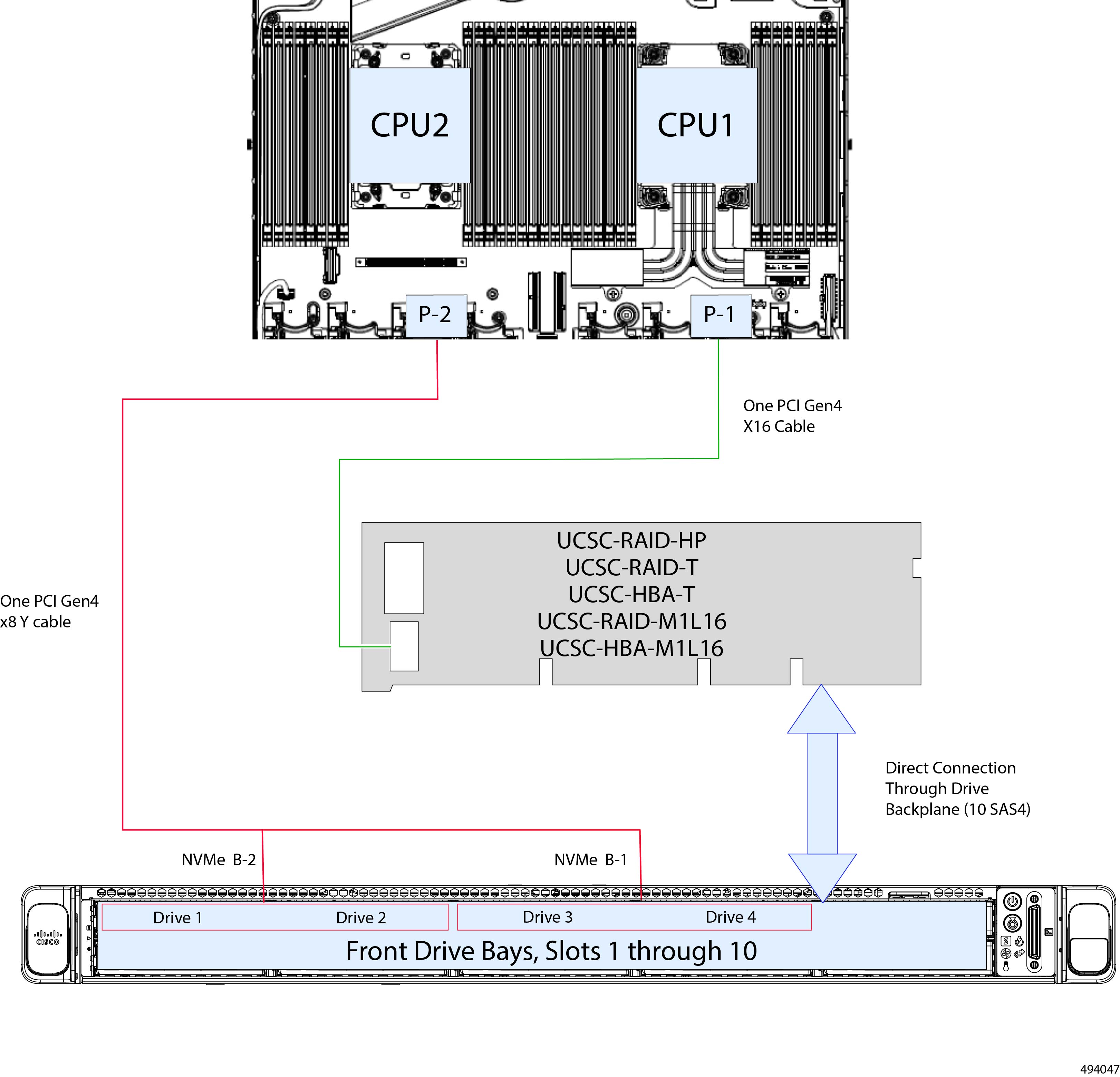
Supported Storage Controllers and Cables

This server supports a single, PCIe-style, SAS RAID or HBA controller that plugs into a dedicated internal riser.


Note


Do not mix controller types in the server.

Note


NVMe PCIe SSDs cannot be controlled by a SAS/SATA RAID controller.

This server supports the RAID and HBA controller options and cable requirements shown in the following table.

Storage Adapter (PID)

Product Name

Supported Server

Maximum Number of Drives Supported

Supported RAID Type

Cache Size (GB)

UCSC-RAID-HP

Cisco 24G Tri-Mode RAID controller with 4GB cache (16 Drives)

UCSC-C220-M7S

10

  • RAID 0

  • RAID 1

  • RAID 5

  • RAID 6

  • RAID 10

  • RAID 50

  • RAID 60

Also supports JBOD mode.

4

UCSC-RAID-T

Cisco 12G SAS RAID Controller with 4GB FBWC (16 Drives)

UCSC-C220-M7S

10

  • RAID 0

  • RAID 1

  • RAID 5

  • RAID 6

  • RAID 10

  • RAID 50

  • RAID 60

Also supports JBOD mode.

4

UCSC-HBA-T

Cisco 12G SAS HBA (16 Drives)

UCSC-C220-M7S

10

SAS HBA

NA

UCSC-RAID-M1L16

Cisco 24G Tri-Mode M1 RAID Controller w/4GB FBWC

UCSC-C220-M7S

10

  • RAID 0

  • RAID 1

  • RAID 5

  • RAID 6

  • RAID 10

  • RAID 50

  • RAID 60

Also supports JBOD mode.

4

UCSC-HBA-M1L16

Cisco 24G Tri-Mode M1 HBA Controller

UCSC-C220-M7S

10

SAS or SATA HBA

NA

Storage Controller Card Firmware Compatibility

Firmware on the storage controller (RAID or HBA) must be verified for compatibility with the current Cisco IMC and BIOS versions that are installed on the server. If not compatible, upgrade or downgrade the storage controller firmware using the Cisco Host Upgrade Utility (HUU) for your firmware release to bring it to a compatible level.

See the HUU guide for your Cisco IMC release for instructions on downloading and using the utility to bring server components to compatible levels: HUU Guides.


Note


For servers running in standalone mode only: After you replace controller hardware, you must run the Cisco Host Upgrade Utility (HUU) to update the controller firmware, even if the firmware Current Version is the same as the Update Version. This is necessary to program the controller's suboem-id to the correct value for the server SKU. If you do not do this, drive enumeration might not display correctly in the software. This issue does not affect servers controlled in UCSM mode.


RAID Backup (Supercap)

This server supports installation of one Supercap unit (UCS-SCAP-D). The unit mounts to a bracket in-line with the fan modules and attaches through the Supercap cable (CBL-SCAP-C220-D).

The optional SCPM provides approximately three years of backup for the disk write-back cache DRAM in the case of a sudden power loss.

For Supercap unit replacement instructions, see Replacing the Supercap (RAID Backup).

Write-Cache Policy for Cisco 12G SAS Modular RAID Controller

For this server, the default write-cache policy for the Cisco Modular RAID controller is Write Through (irrespective of the presence of a charged SuperCap or “good BBU”). This utilizes the optimal performance characteristics of the controller.

The write policy can be set to Write Back, if preferred. You can set the write policy using the following methods:

  • For standalone servers, use the Cisco IMC interface to set Virtual Drive Properties > Write Policy. See the “Managing Storage Adapters” section in your Cisco IMC Configuration Guide.

    Cisco IMC GUI and CLI Configuration Guides

  • For Cisco UCS-integrated servers, use the Cisco UCS Manager interface to set the write-cache policy as part of virtual drive configuration in your storage profile.

    Cisco UCS Manager Configuration Guides

  • Use the LSI Option ROM Configuration Utility.

Mixing Drive Types in RAID Groups

For the best performance follow these guidelines:

  • Use either all SAS or all SATA drives in a RAID group.

  • Use the same capacity for each drive in the RAID group.

  • Never mix HDDs and SSDs in the same RAID group.

RAID Controller Migration

This server supports SAS/SATA hardware RAID (controller card) and embedded software SATA RAID. You cannot use hardware RAID and software RAID at the same time. See the table below for which data migrations are allowed and a summary of migration steps.

Starting RAID Controller

Migrate to Hardware RAID Allowed?

Migrate to Software RAID Allowed?

None (no drives).

Embedded RAID is disabled in the BIOS.

Allowed

  1. Install RAID card.

  2. Install SAS cables.

Allowed

  1. Install SATA interposer card.

  2. Install SATA cables.

  3. Enable embedded RAID in BIOS.

Embedded software RAID.

Embedded RAID is enabled in the BIOS.

Caution

 
Data migration from software RAID to hardware RAID is not supported and could result in data loss.

Allowed only before there is data on the drives; data migration is not supported.

  1. Disable embedded RAID in the BIOS.

  2. Install RAID card.

  3. Install SAS cables.

-

Hardware RAID.

Embedded RAID is disabled in the BIOS.

-

Not allowed.

Storage Controller and Backplane Connectors

This section describes cabling connections for the storage controllers and the backplane. The SAS/SATA cables are factory-installed and are used for all supported internal controllers in the SFF 10-drive version of the server. However, the controller and cables are available as spares if you need to replace them. S

This section also contains diagrams that show the cable-to-drive mapping.


Note


The SFF 10-drive version with NVMe drives only does not use SAS or SATA RAID. This version of the server comes with a PCIe cable that directly connects the drives with the MB. Of the 10 front-loading drives, up to four can be NVME drives installed in slots 1 through 4. NVMe drives are connect in pairs to the motherboard through the NVMe B2 or NVMe B1 connectors on the drive backplane. These drives are directly connected to the mother board CPU2 socket through a PCIe Y cable (CBL-FNVME-C220M7= ).

Cisco UCSC-RAID-HP, Cisco UCSC-RAID-T or UCSC-HBA-T, and UCSC-RAID-M1L16 or Cisco UCSC-HBA-M1L16

The card supports up to ten front-loading SAS/SATA data drives that plug directly into their slots on the drive backplane. The RAID card connects to the motherboard CPU1 socket through a PCIe cable.

Although the same cabling diagram is standard across all versions of storage controller, there is a slight difference that depends on whether the card requires a Y cable or a straight-through cable. To connect the drives to the storage controller, use the appropriate procedure.

  • Controllers RAID-HP, HBA-M1L16, RAID-M1L16 use a Y cable.

  • Controllers RAID-T-SD and SAS-T-D, use a straight-through cable.

Procedure for RAID-HP, HBA-M1L16 and RAID-M1L16

  1. Assuming the controller is installed in the chassis, connect one end a PCIe Gen 4 x16 cable (CBL-SAS-Y-C220M7=) to the connector on the controller.

  2. Connect the other end of the cable to the P-1 connector on the motherboard at the base of CPU1's heatsink.

This server can support up to four NVMe drives in slots one through four. These drives are not connected to the RAID/HBA controller. Instead, they are directly connected to the motherboard as shown:

  1. Connect the dual-end of the PCIe Gen 4 x8 Y cable to ports NVMe B-2 (for drives 1 and 2) and B-1 (for drives 3 and 4) on the drive backplane.

  2. Connect the single-end of the Y cable to the P-2 connector on the motherboard at the base of CPU 2.

Procedure for RAID-T-SD and SAS-T-D

  1. Assuming the controller is installed in the chassis, connect one end a PCIe Gen 4 x16 cable (CBL-SAS-C220M7=) to the connector on the controller.

  2. Connect the other end of the cable to the P-1 connector on the motherboard at the base of CPU1's heatsink.

This server can support up to four NVMe drives in slots one through four. These drives are not connected to the RAID/HBA controller. Instead, they are directly connected to the motherboard as shown:

  1. Connect the dual-end of the PCIe Gen 4 x8 Y cable to ports NVMe B-2 (for drives 1 and 2) and B-1 (for drives 3 and 4) on the drive backplane.

  2. Connect the single-end of the Y cable to the P-2 connector on the motherboard at the base of CPU 2.

For More RAID Utility Information

The Broadcom utilities have help documentation for more information about using the utilities.