Cisco Unified Edge and Red Hat OpenShift Single Node Cluster Deployment Guide
Available Languages
Bias-Free Language
The documentation set for this product strives to use bias-free language. For the purposes of this documentation set, bias-free is defined as language that does not imply discrimination based on age, disability, gender, racial identity, ethnic identity, sexual orientation, socioeconomic status, and intersectionality. Exceptions may be present in the documentation due to language that is hardcoded in the user interfaces of the product software, language used based on RFP documentation, or language that is used by a referenced third-party product. Learn more about how Cisco is using Inclusive Language.
- US/Canada 800-553-2447
- Worldwide Support Phone Numbers
- All Tools
 Feedback
 Feedback
In partnership with:
![]()
Executive Summary
We’re at a critical inflection point. The edge has emerged as the place where the physical and digital worlds meet, demanding real-time processing and analysis of data to deliver informed decisions, improved experiences, and increased productivity. However, legacy infrastructure wasn’t built for the AI era and can’t keep up with the scale, speed, and intelligence required by AI-driven operations. While much of the model training happens in the data center, the shift of test-time inference to the edge makes it the new frontier for enterprise AI.
Deploying AI at the edge remains complicated and demanding. Interoperability, security, cost, and rigid deployment models are all potential performance and productivity blockers. The increasing demand for AI and digitization at the edge necessitates a full system rethink, as evolving business needs and the sheer scale of highly distributed edge environments and modern AI workloads create a beyond-human complexity nightmare. We need something more than just more boxes; we need a brand-new edge infrastructure and operations vision.
Cisco Unified Edge is an AI-ready system that redefines computing at the edge by converging compute, networking, storage, and security. Designed from the edge up, for the next decade, the modular design is future-ready, energy-efficient, and easy-to-service, and can be tailored to support today’s workloads and use cases, while remaining adaptable to the rapidly evolving AI landscape. Seamless integration with third-party technologies and validated solutions for industry-specific needs ensure both compatibility and optimized performance.
Delivering breakthrough operational simplicity at scale, this software-defined system features centralized cloud management, zero-touch deployment, curated blueprints, and automated orchestration. These capabilities enable high scalability with minimal complexity. End-to-end observability with real-time analytics accelerates error detection and correction, helping minimize service outages. Security is designed-in, with integrated physical and digital safeguards to protect applications and data at the edge while multi-layered security capabilities protect infrastructure, applications, and AI models.
Benefits
The key benefits are:
● Future-ready performance: Adaptable to meet today and tomorrow's edge workload demands with ease, stopping the rip-and-replace cycle with a fully integrated, modular edge environment built for the next decade. Deploy applications and infrastructure faster and profit sooner with proven solutions that are tested and certified for vertical-specific workloads and use cases, ensuring compatibility and performance.
● Full-scale simplicity: Onboard quickly and with ease without the need for highly skilled IT expertise or on-site visits. Whether deploying ten systems or ten thousand, zero-touch provisioning, curated blueprints and automation ensure consistent, effortless rollout. A consistent operating model from core to edge makes it easy to scale, upgrade, and support your infrastructure.
● Designed-in security: Prevent tampering at the edge with robust physical and digital protection. Proven policy-based templates eliminate configuration drift across sites. Embedded, zero-trust security capabilities ensure unmatched protection for your edge infrastructure, data, and AI models.
Red Hat, the leading provider of enterprise open-source solutions, offers a comprehensive and integrated portfolio of technologies designed to modernize enterprise IT operations, accelerate innovation, and reduce complexity across hybrid cloud, datacenter, and edge environments. This technical design guide explores how Red Hat's enterprise platform can be effectively deployed on Cisco Unified Edge System (Cisco UCS XE9305) to deliver scalable, secure, and mission-critical solutions.
Red Hat's enterprise-grade architecture aligns seamlessly with Cisco Unified Edge infrastructure model, enabling:
● Rapid provisioning and scaling of containerized and virtualized workloads
● Unified management and automation across compute, storage, and networking
● Optimized performance for cloud-native applications, traditional workloads, and AI/ML inference
● Enterprise support and certified interoperability for production environments
Together, Red Hat and Cisco Unified Edge empower enterprises to build resilient, future-ready platforms that support digital transformation, edge computing, and AI innovation.
The design of this solution is driven by its ability to evolve and incorporate both technology and product innovations in the areas of management, computing, storage, and networking to be used at the edge. To help organizations with their digital transformation and application modernization practices, Cisco and Red Hat have partnered to produce this Cisco Validated Design (CVD) for the joint Unified Edge and Red Hat edge solutions minimizing risks by validating the integrated architecture to ensure compatibility between various components. The solution also addresses pain points by providing documented design guidance, deployment guidance, and support that can be used in various stages (planning, designing, and implementation) of a business project targeting Edge deployments. The solution is part of Cisco’s Blueprint and Fleet management enhancement of Intersight and will be delivered as Infrastructure as Code (IaC) to further eliminate error-prone manual tasks, allowing quicker and more consistent solution deployments.
Solution Overview
This chapter contains the following:
The deployment options use pre-designed, integrated, and validated architectures for the edge that combines Cisco Unified Edge - servers, network, security - and Red Hat products into a single, flexible architecture. The solutions are designed to meet a broad range of deployment options, while maintaining cost-effectiveness and flexibility to support a wide variety of workloads.
The range of deployment options goes from a single node Linux host to run a small number of virtual machines or containers up to a multi-node Kubernetes cluster with an integrated software defined storage option to provide full high-availability and scalability for a larger number of virtual machines, container-based applications, AI workloads and mission critical control units.
The following design and deployment aspects of this edge solution are explained in this document:
● Cisco Unified Edge
● Single node OpenShift cluster
● Deployment options for virtual machines and container-based workloads
● Integration into edge networks
The intended audience of this document includes but is not limited to IT architects, sales engineers, field consultants, professional services, IT managers, partner engineering, and those who want to take advantage of an infrastructure built to deliver efficiency and enable innovation.
This document provides design guidance around incorporating the Cisco Intersight—managed Cisco Unified Edge platform to run Red Hat edge solutions. The document introduces various design elements and covers various considerations and best practices for a successful deployment.
The components are integrated and validated, and where possible, Intersight Blueprints will explain the installation and configuration of the entire stack so that you can deploy your solution quickly and economically, while eliminating many of the risks associated with researching, designing, building, and deploying similar solutions from the ground up.
The Cisco Unified Edge with Red Hat edge solution offers the following key benefits:
● Standardized architecture for quick, repeatable, error-free deployments of workload domains
● Automated life cycle management to keep all the system components up to date
● Simplified cloud-based management of various components
● Hybrid-cloud-ready, policy-driven modular design
● Highly available, flexible, and scalable architecture
● Cooperative support model and Cisco Solution Support
● Easy to deploy, consume, and manage design that aligns with Cisco and Red Hat best practices and compatibility requirements
● Support for component monitoring, solution automation and orchestration, and workload optimization
● Validated integration into Meraki and Catalyst network domains.
Like all other Cisco Validated solution designs, Cisco Unified Edge with Red Hat is configurable according to demand and usage. You can purchase the exact infrastructure needed for your current application requirements. You can scale-up by adding more resources to the solution or scale-out by adding more Unified Edge instances.
Technology Overview
This chapter contains the following:
Cisco Unified Edge with Red Hat is built using compute, network, and storage components integrated in the Unified Edge platform. The solution consists of the following core elements:
● Cisco Unified Edge System (Cisco UCS XE9305)
● Red Hat OpenShift
One of the key benefits of Cisco Unified Edge is its ability to maintain consistency during scale where required. Each of the components offers platform and resource options to scale the infrastructure up or down while supporting the same features and functionality that are required under the configuration and connectivity best practices. The key features and highlights of the components are explained in the following sections.
Cisco Unified Edge is part of the Cisco Unified Computing System (Cisco UCS) family designed from the ground up to address deployments where traditional data center servers are not a perfect fit. With its new physical design and the new components, the Cisco Unified Edge uses, like other Cisco UCS platforms, Cisco Intersight as the management tool.
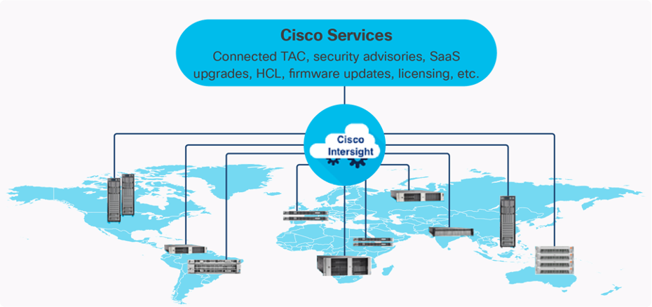
The Cisco Intersight platform is a Software-as-a-Service (SaaS) infrastructure lifecycle management platform that delivers simplified configuration, deployment, maintenance, and support. The Cisco Intersight platform is designed to be modular, so you can adopt services based on your individual requirements. The platform significantly simplifies IT operations by bridging applications with infrastructure, providing visibility and management from bare-metal servers and hypervisors to serverless applications, thereby reducing costs and mitigating risk. This unified SaaS platform uses an Open API design that natively integrates with third-party platforms and tools.
The capabilities of Cisco Intersight were extended with a Fleet Management option to automate and accelerate deployment of Cisco UCS and Unified Edge systems at remote locations at scale. With the new Fleet Management, it is possible to define location profiles and Blueprints to allow zero-touch provisioning of the hardware and operating systems as soon as the new hardware is claimed in Intersight.
While the Cisco UCS XE9305 is a programmable infrastructure, the Cisco Intersight API is how management tools program it. This enables the tools to help guarantee consistent, error-free, policy-based alignment of server personalities with workloads. Through automation, transforming the server and networking components of your infrastructure into a complete solution is fast and error-free because programmability eliminates the error-prone manual configuration of servers and integration into solutions. Server, network, and storage administrators are now free to focus on strategic initiatives rather than spending their time performing tedious tasks.
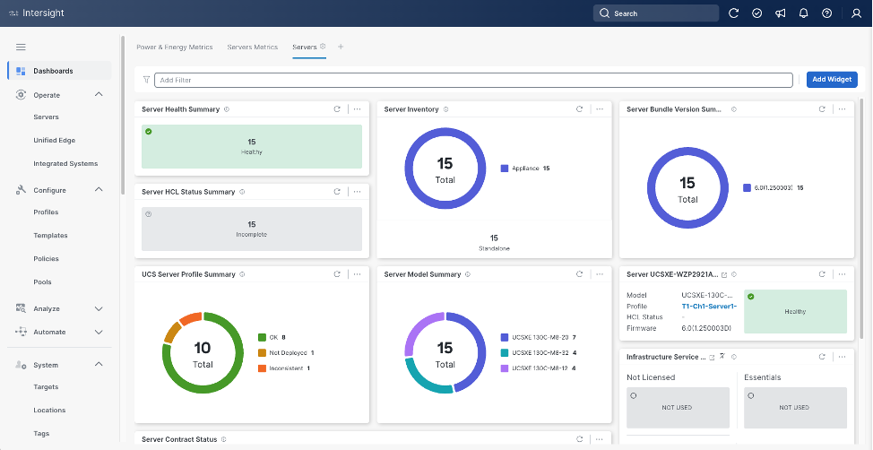
The main benefits of Cisco Intersight infrastructure services are as follows:
● Simplify daily operations by automating many daily manual tasks
● Combine the convenience of a SaaS platform with the capability to connect from anywhere and manage infrastructure through a browser or mobile app
● Stay ahead of problems and accelerate trouble resolution through advanced support capabilities
● Gain global visibility of infrastructure health and status along with advanced management and support capabilities
Licensing Requirements
The Cisco Intersight platform uses a subscription-based license with multiple tiers. You can purchase a subscription duration of one, three, or five years and choose the required Cisco UCS server volume tier for the selected subscription duration. Each Cisco endpoint automatically includes a Cisco Intersight Base license at no additional cost when you access the Cisco Intersight portal and claim a device. You can purchase any of the following higher-tier Cisco Intersight licenses using the Cisco ordering tool:
● Cisco Intersight Infrastructure Services Essentials: The Essentials license tier offers server management with global health monitoring, inventory, proactive support through Cisco TAC integration, multi-factor authentication, along with SDK and API access.
● Cisco Intersight Infrastructure Services Advantage: The Advantage license tier offers advanced server management with extended visibility, ecosystem integration, and automation of Cisco and third-party hardware and software, along with multi-domain solutions.
Servers in the Cisco Intersight managed mode require at least the Essentials license. For detailed information about the features provided in the various licensing tiers, see https://intersight.com/help/getting_started#licensing_requirements.
DevOps and Tool Support
The Cisco Intersight API is of great benefit to developers and administrators who want to treat physical infrastructure the way they treat other application services, using processes that automatically provision or change IT resources. Similarly, your IT staff needs to provision, configure, and monitor physical and virtual resources; automate routine activities; and rapidly isolate and resolve problems. The Cisco Intersight API integrates with DevOps management tools and processes and enables you to easily adopt DevOps methodologies.
The Cisco Unified Edge Modular System is designed to take the current generation of the Cisco UCS platform to the next level with its future-ready design and cloud-based management. Decoupling and moving the platform management to the cloud allows Cisco UCS to respond to customer feature and scalability requirements in a much faster and more efficient manner. Cisco Unified Edge’s state-of-the-art hardware simplifies the edge design by providing flexible server options.
Cisco UCS XE9305 Chassis
The Cisco Unified Edge chassis is engineered to be adaptable and flexible. As seen in Figure 3, the Cisco Unified Edge XE9305 chassis has a power-distribution backplane. This innovative design provides fewer obstructions for better airflow.
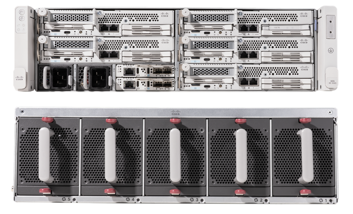
The Cisco UCS XE9305 3-Rack-Unit (3RU) chassis has five flexible slots. These slots can house a combination of compute nodes and network nodes (future). At the bottom of the chassis are two edge Chassis Management Controller (eCMC) that connect the chassis to upstream network. On the left of the eCMCs, two Power Supply Units (PSUs) provide power to the chassis with N+N redundancy. At the back of the chassis, five efficient, 80mm, dual counter-rotating fans deliver industry-leading airflow and power efficiency, and optimized thermal algorithms enable different cooling modes to best support the customer’s environment.
Cisco Unified Edge – Edge Chassis Management Controller
The Cisco Edge Chassis Management Controller (eCMC) provides a single point for connectivity and management for the entire Cisco Unified Edge system.
The Cisco Unified Edge eCMC provides the management and communication backbone for the Cisco UCS XE130c M8 compute nodes in the Cisco UCS XE9305 Series Chassis. All nodes attached to the Cisco Unified Edge eCMC become part of a single, highly available management domain.
The Cisco Unified Edge eCMC utilized in the current design includes one Ethernet port for management, two Ethernet ports for data traffic, and one Ethernet port to each slot in the chassis.
Cisco UCS XE130c M8 Compute Node
The Cisco UCS XE9305 Chassis is designed to host up to five Cisco UCS XE130c Compute Nodes. The hardware details of the Cisco UCS XE130c M8 Compute Nodes are shown in Figure 4:
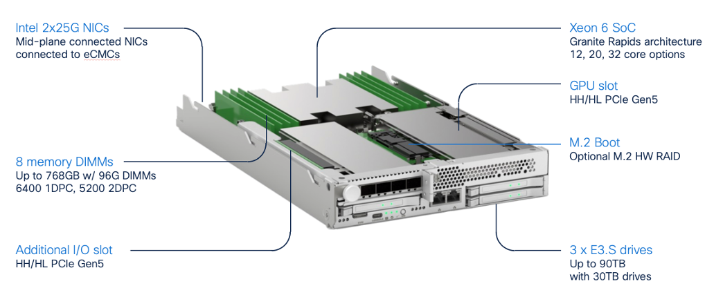
The Cisco UCS XE130c M8 features:
● CPU: One 6th Gen Intel Xeon SoC Processor with 12, 20, or 32 cores.
● Memory: Up to 8 x 96 GB DDR5-6400 DIMMs for a maximum of 768 GB of main memory.
● Disk storage: Up to 4 E3.s NVMe drives (with storage optimized SKU) and one M.2 RAID controller with two M.2 memory cards with RAID 1 mirroring.
● LAN on Mainboard (LoM): Intel E825 NIC is integrated in the Xeon SoC Processor with two 25 Gbps ports on the Mid-plane and two 1/10 Gbps RJ45 ports on the front of each Compute Node.
● GPU: Dedicated PCIe Gen-5 slot for one HH/HL GPU with up to 75 Watt.
● Security: The server supports an optional Trusted Platform Module (TPM).
This Cisco Unified Edge Solution with Red Hat was tested using both Cisco Catalyst and Cisco Meraki network domains.
Graphics Processing Units or GPUs are specialized processors designed to render images, animation and video for computer displays. They perform these tasks by running many operations simultaneously. While the number and kinds of operations they can do are limited, GPUs can run many thousand operations in parallel making this massive parallelism extremely useful for deep learning applications. Deep learning relies on GPU acceleration for both training and inference, and GPU accelerated datacenters deliver breakthrough performance with fewer servers at a lower cost. This CVD details the below NVIDIA GPUs:
NVIDIA L4 Tensor Core GPU
The NVIDIA L4 Tensor Core, powered by the Ada Lovelace architecture, is a versatile and energy-efficient accelerator designed for workloads such as AI, video processing, graphics, and virtualization. Its low-profile form factor and high performance make it suitable for deployment across edge, data center, and cloud environments.
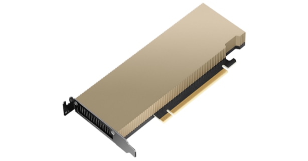
The NVIDIA L4 card is a single-slot PCI Express Gen4 card. It uses a passive heat sink for cooling, which requires system airflow to operate the card properly within its thermal limits. The NVIDIA L4 PCIe operates unconstrained up to its maximum thermal design power (TDP) level of 72 W to accelerate applications that require the fastest computational speed and highest data throughput at the edge.
The software layer of the NVIDIA AI platform, NVIDIA AI Enterprise, accelerates the data science pipeline and streamlines the development and deployment of production AI including generative AI, computer vision, speech AI and more. With over 50 frameworks, pre-trained models, and development tools, NVIDIA AI Enterprise is designed to accelerate enterprises to the leading edge of AI while simplifying AI to make it accessible to every enterprise.
OpenShift is a Kubernetes-based container application platform that automates the deployment, scaling, and management of containerized workloads. It provides an integrated developer and operations experience with built-in CI/CD, image management, and application templates. OpenShift adds enterprise features on top of Kubernetes, including advanced security, policy enforcement, and multi-tenancy. It supports hybrid and multi-cloud deployments, enabling consistent application environments across on-premises and public cloud infrastructure.
AI Inferencing at the Edge Landscape
AI inferencing at the edge enables real-time decision-making by processing data locally on devices, gateways, or micro data centers instead of relying solely on centralized cloud infrastructure. This decentralized approach is vital in latency-sensitive, bandwidth-constrained, or privacy-focused environments where immediate action is required, and network connectivity may be intermittent.
Key Use Cases and Benefits
● Industrial Automation and Predictive Maintenance - Enables real-time predictive maintenance by analyzing sensor data locally, reducing downtime and maintenance costs.
● Retail Intelligence and Smart Environments - Uses smart cameras and AI analytics at the edge to optimize customer experience, shelf layouts, and inventory management.
● Healthcare Diagnostics - Processes patient vitals and imaging data on edge devices for instant diagnostics while maintaining data privacy.
● Security and Surveillance - Performs on-site AI-based threat detection, facial recognition, and anomaly monitoring with minimal latency.
● Smart Agriculture - Employs drones and sensors running AI models to assess crop health, detect pests, and optimize irrigation in real time.
Cisco Unified Edge with Single Node OpenShift Cluster Deployment
This chapter contains the following:
Configure Cisco Unified Edge Using Intersight
Install and Configure SNO Using Assisted Installer
Install and Configure SNO Using CLI and YAMLs
Before deploying an OpenShift Single Node Cluster (SNO) on Cisco Unified Edge, you must ensure that essential infrastructure services are available and properly configured. These services provide the foundation for successful cluster deployment and operation at both Unified Edge and OpenShift levels. You can deploy these services at edge locations or leverage existing services in the regional data center.
Required Infrastructure Services:
● Workstation - A system with internet access to both Cisco Intersight and Red Hat Hybrid Cloud Console, along with required deployment tools
● DHCP Server - For automatic IP address assignment during installation
● NTP Server - To ensure time synchronization across the cluster
● DNS Servers - For name resolution and cluster service discovery
The validated solution includes a Cisco UCS XE9305 chassis with up to 5 Cisco UCS XE130c M8 compute nodes.
● Cisco UCS XE9305 chassis is connected to a pair of Meraki MS (C9300L-24UXG-4X) switches. The first eCMC connects both of its 10 GbE uplinks via a port-channel to the first switch, while the second eCMC connects its bundled uplinks entirely to the second switch.
● Each Cisco UCSXE-eCMC-G1’s management port is connected to a separate Meraki MS switch.
● Two 10GbE links provide connectivity between two Meraki MS switches. Both links are bundled as a port-channel for increased bandwidth and link redundancy.
● Each switch is connected to the same Meraki MX using a 1GbE link.
● Meraki MX68W uses dedicated Internet/WAN ports to connect to ISP for Internet connectivity
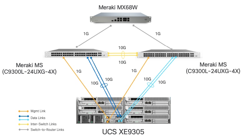
Table 1. VLAN and Network Usage
| VLAN Name |
VLAN ID |
IP Subnet |
Subnet Mask |
Default Gateway |
MTU |
| OOB-MGMT-VLAN |
1315 |
10.131.5.0 |
255.255.255.0 |
10.131.5.1 |
1500 |
| IB-MGMT-VLAN |
1316 |
10.131.6.0 |
255.255.255.0 |
10.131.6.6 |
1500 |
| ACCESS-VLAN |
1317 |
10.131.7.0 |
255.255.255.0 |
10.131.7.1 |
1500 |
| WORKLOAD-VLAN |
1318 |
10.131.8.0 |
255.255.255.0 |
10.131.8.1 |
1500 |
Some of the key highlights of VLAN usage in the validated design are shown below:
● VLAN 1315 allows you to manage and access out-of-band management interfaces of various devices and is brought into the infrastructure to allow IMC access to the Unified Edge eCMC.
● VLAN 1316 serves as the in-band management VLAN which is required to use vMedia policy and CIMC-Mounted ISO images inside Unified Edge. It is also the Native VLAN to allow network traffic to the next-hop switch without VLAN tagging.
● VLAN 1317 is used to access the OpenShift host.
● VLAN 1318 is added to provide an additional interface that connects virtual machines to the dedicated or isolated network.
Configure Cisco Unified Edge Using Intersight
The deployment of Cisco UCS XE9305 Unified Edge devices through Intersight uses a template-based approach that streamlines configuration management across both chassis and compute resources. Follow these stages to complete the configuration:
● Claim the Unified Edge Device: Register the Cisco UCS XE9305 to Cisco Intersight using the claim code to enable cloud-based management and monitoring.
● Build the Unified Edge Profile Template: Create the necessary Unified Edge policies first and associate them with a Unified Edge Profile Template that defines chassis-level configurations.
● Apply Unified Edge Configuration: Generate a Unified Edge Profile from the template and bind it to the target Cisco UCS XE9305.
● Create Server Profile Template: Create the necessary Server Policies first, then build a Server Profile Template that references these policies to define comprehensive compute node configurations.
● Provision Servers: Instantiate Server Profiles from the template and associate them with individual Cisco UCSXE-130C-M8 servers.
● Activate Tunnel KVM Access: Enable the Tunnel KVM capability to allow secure remote console access to servers directly from the Intersight interface.
Claim a Cisco Unified Edge UCS XE9305 Chassis in Cisco Intersight
After getting out-of-band management IP addresses, Cisco Unified Edge UCS XE9305 device needs to be claimed to a new or an existing Cisco Intersight account. When a UCS XE9305 is successfully added to Cisco Intersight, all future configuration steps are completed in the Cisco Intersight portal.
Procedure 1. Claim Unified Edge in Cisco Intersight
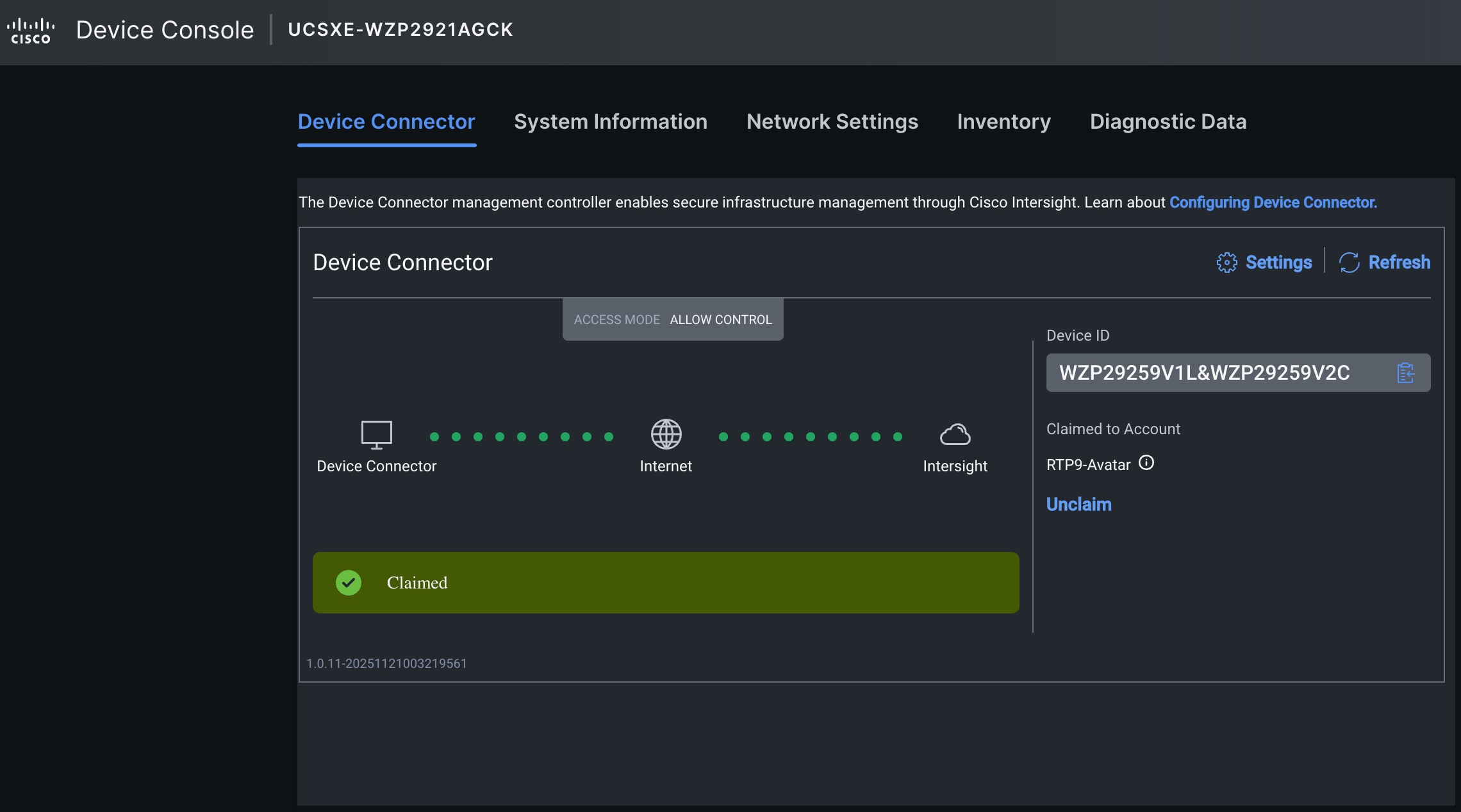
Step 1. Use the management IP address of one Unified Edge eCMC to access the device from a web browser and log in with the previously configured admin password.
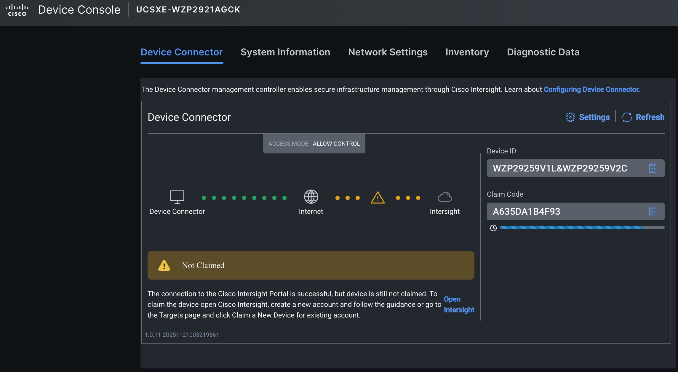
Step 2. Under DEVICE CONNECTOR, the current device status will show Not claimed. Note or copy the Device ID and Claim Code information for claiming the device in Cisco Intersight.
Step 3. Log into Cisco Intersight.
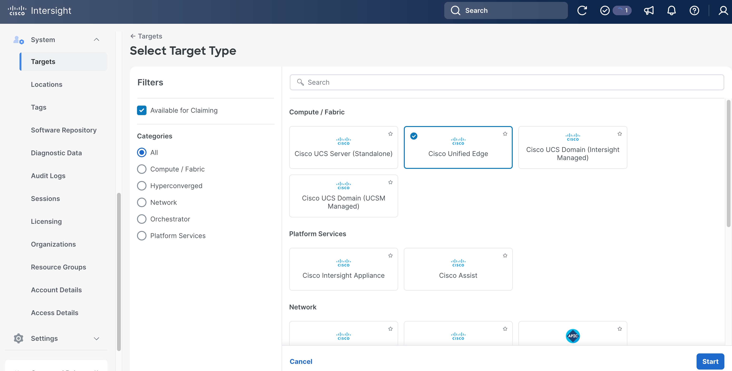
Step 4. Go to System > Targets , then click Claim a New Target.
Step 5. Select Cisco Unified Edge and click Start.
Step 6. Copy and paste the Device ID and Claim Code from the previous step to Intersight.
Step 7. Select the correct resource group and click Claim.
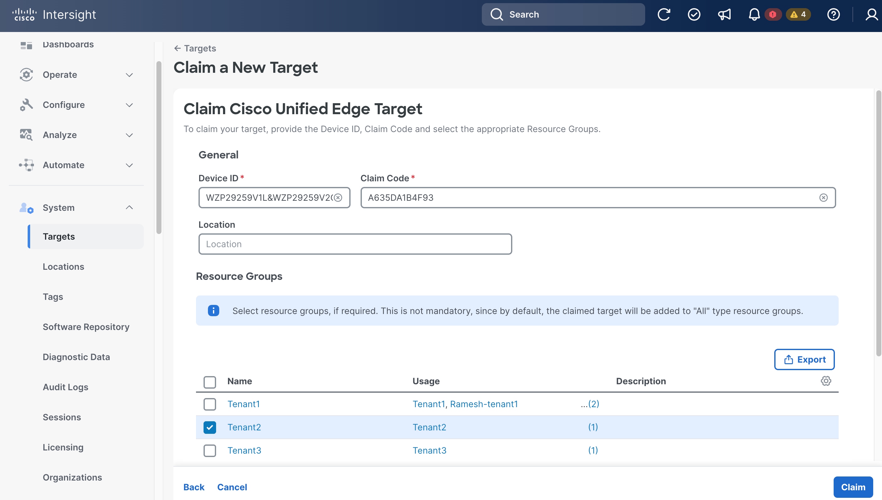
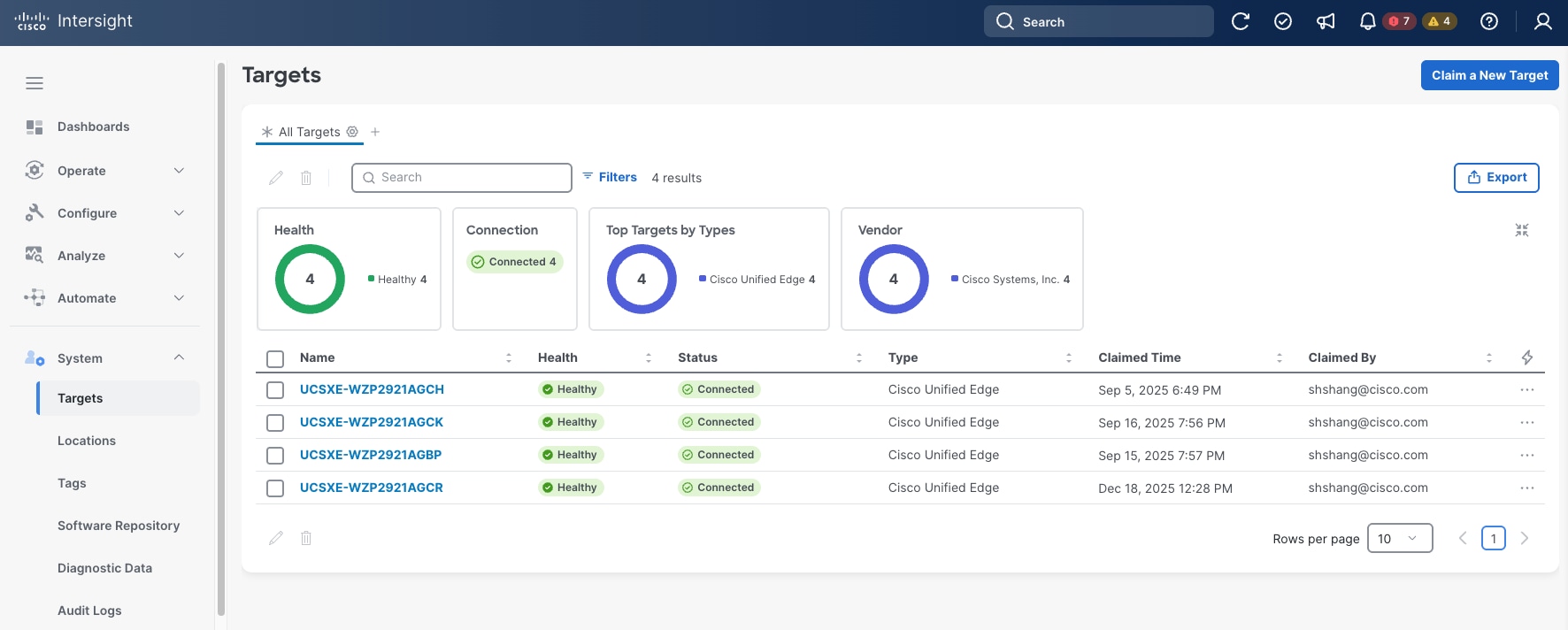
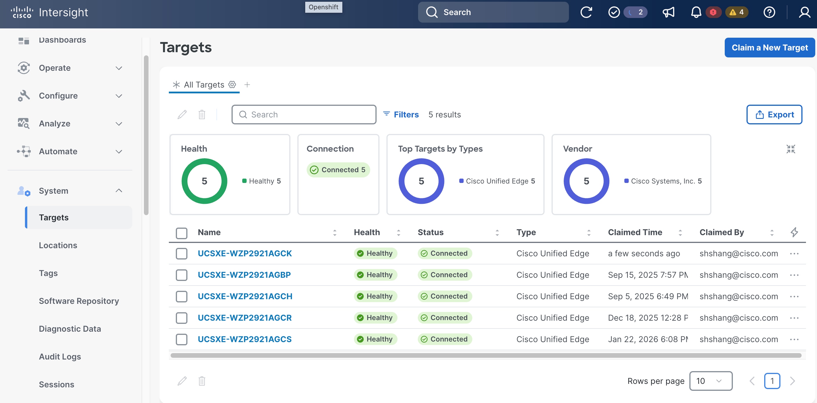
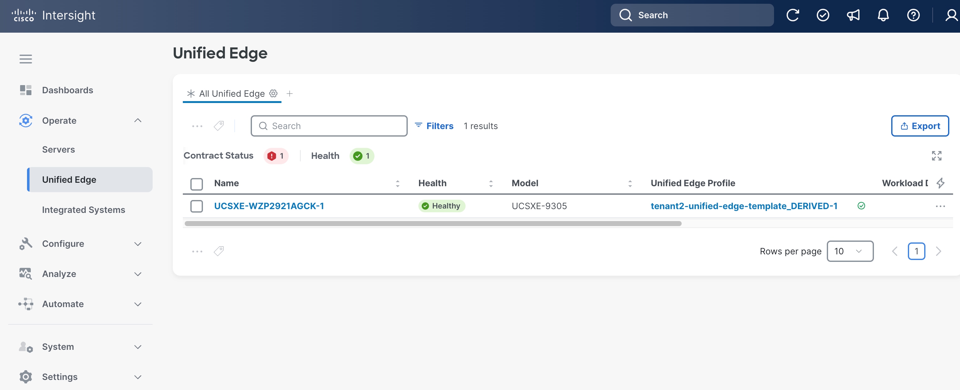
With a successful device claim, Cisco Unified Edge device (UCSXE-WZP2921AGCK), appears as a target in Cisco Intersight:
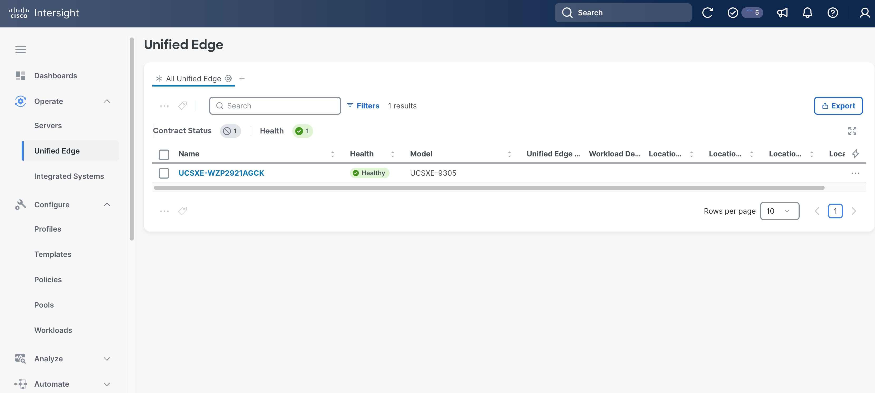
Step 8. Go to Operate > Unified Edge, the claimed Unified Edge device should show up. Verify the Health status is Healthy.
Step 9. Log back into Device Console by using one of the eCMC management IP addresses, click Refresh. The Device Connector status is changed to Claimed.
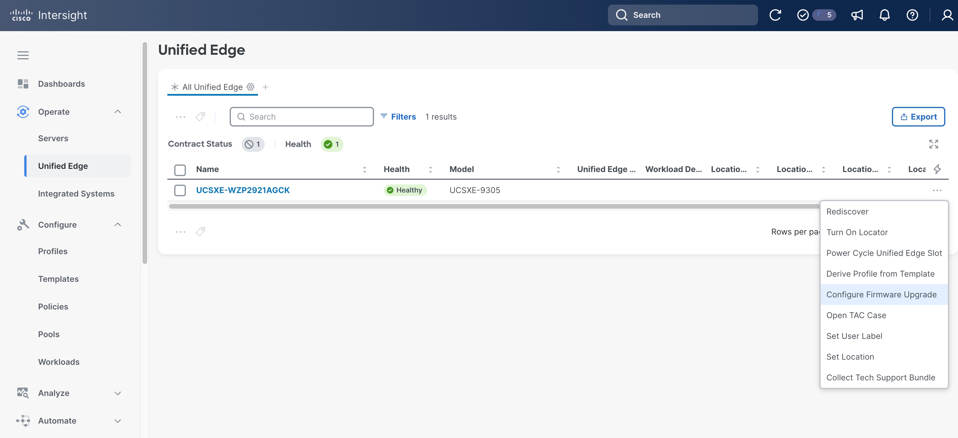
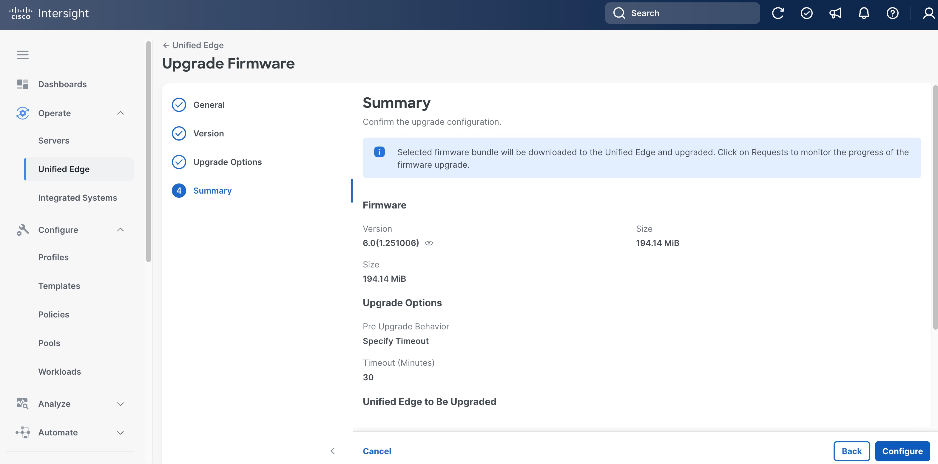
Procedure 2. Upgrade Unified Edge Firmware (Optional)
Step 1. Go to Operate > Unified Edge, select the UCS XE9305 device, click the ellipses (…) at the end of the row. From the drop-down list, select Configure Firmware Upgrade.
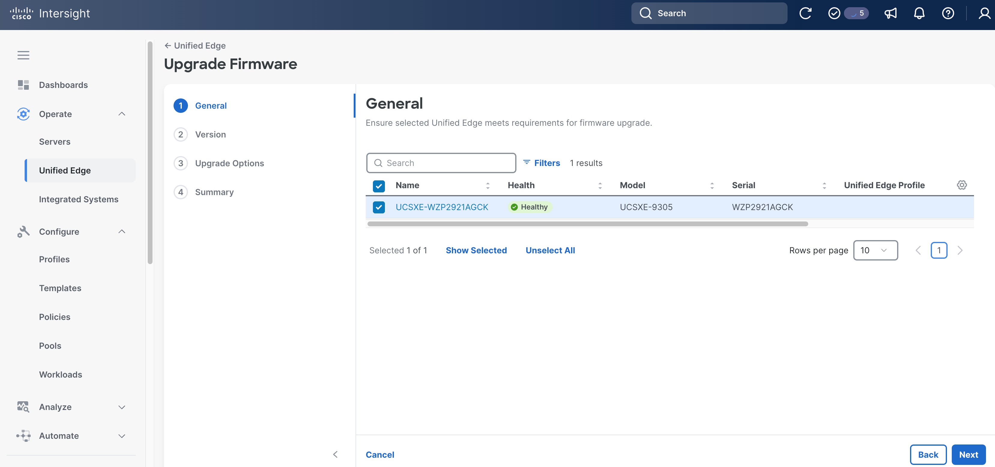
Step 2. On the General page, click Next.
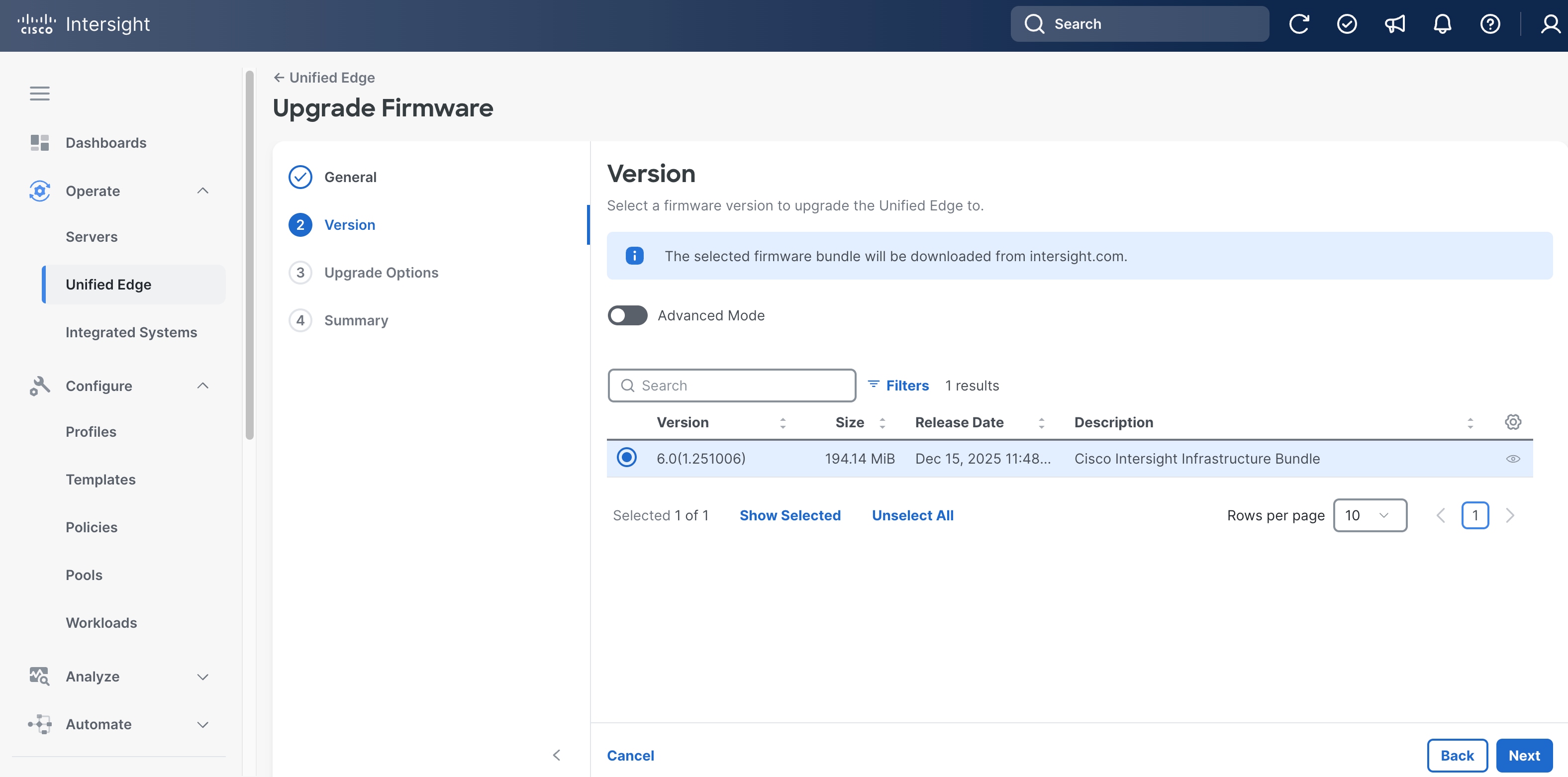
Step 3. On the Version page, select the target bundle release, which is 6.0(1.251006) in this example.
Step 4. Click Next.
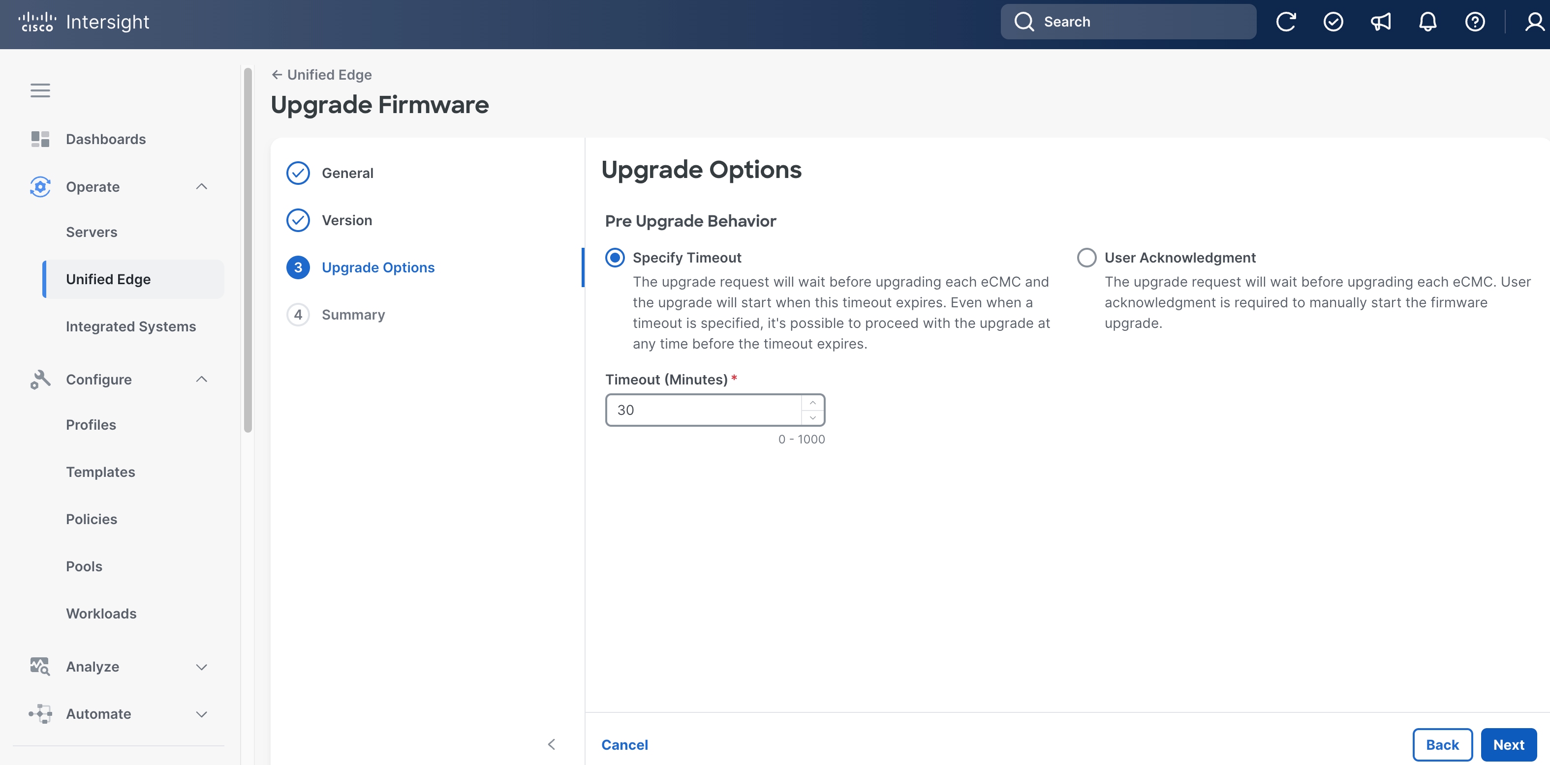
Step 5. On the Upgrade Options page, leave everything at their default settings.
Step 6. Click Next.
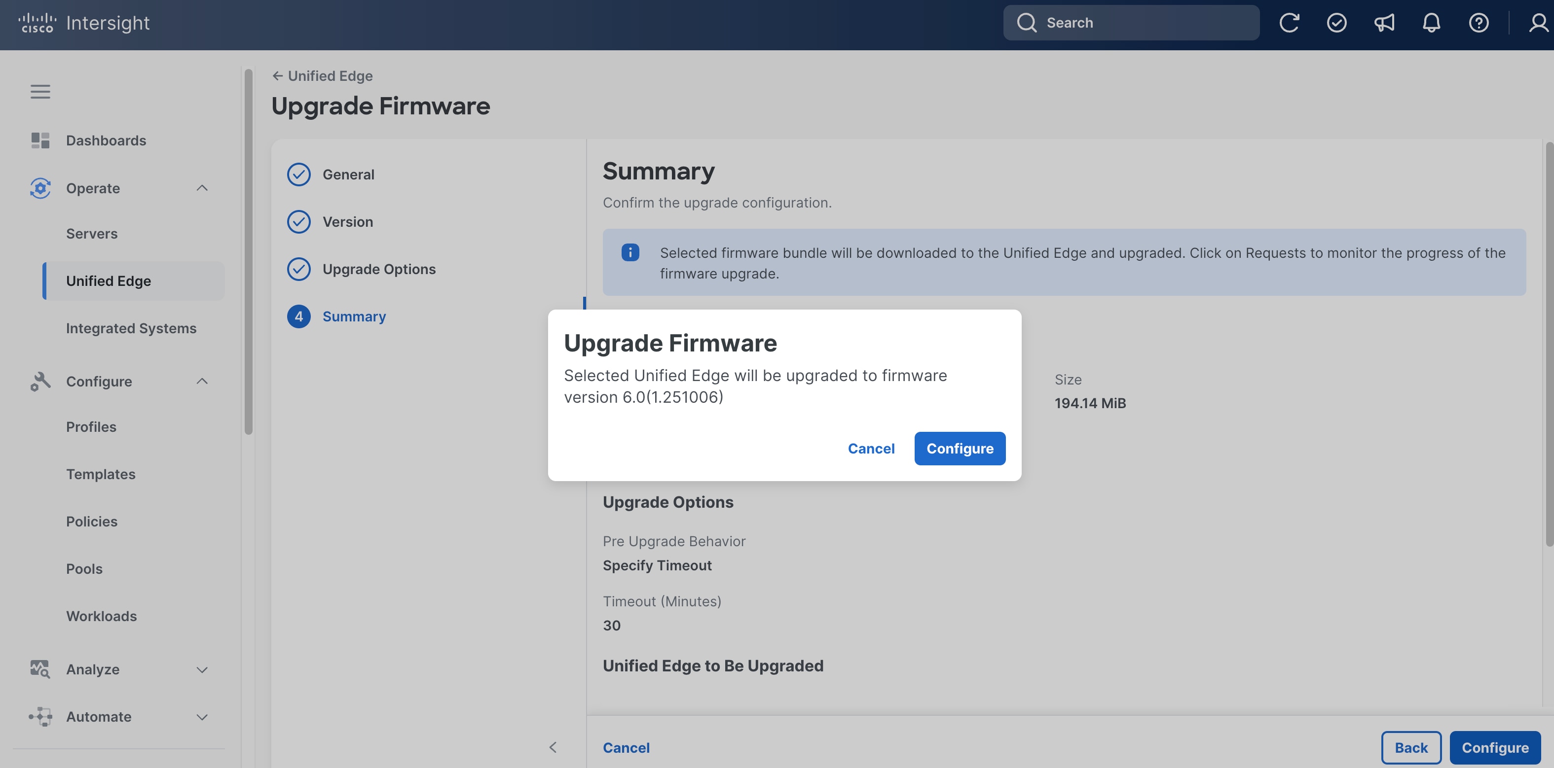
Step 7. On the Summary page, click Configure.
Step 8. In the pop-up window, click Configure.
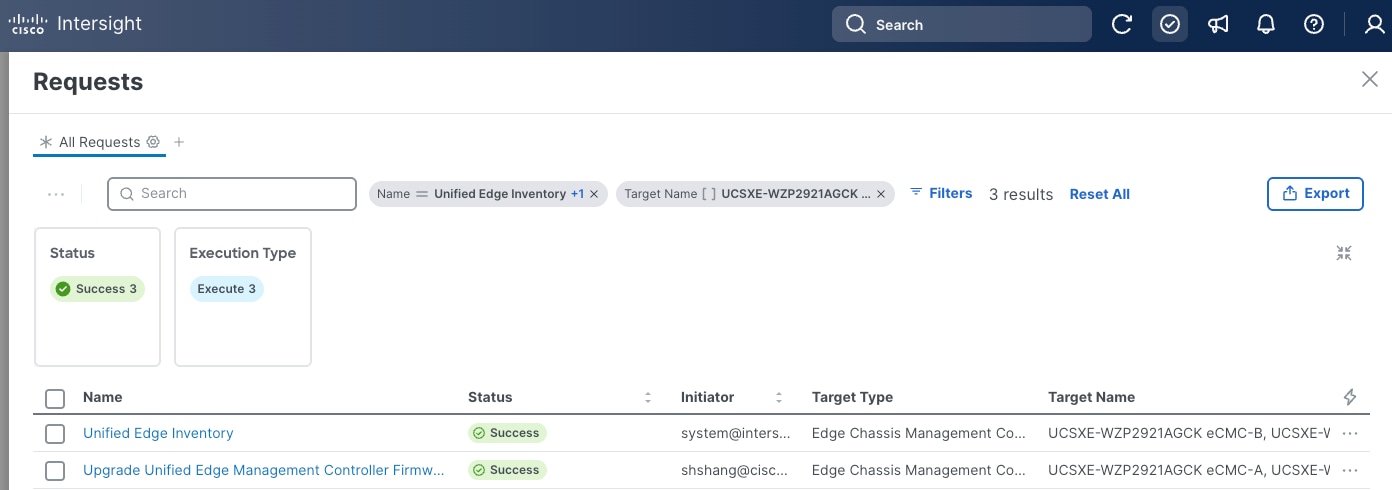
Step 9. Click the checkmark icon at upper-right corner to monitor the status of firmware upgrade request. It will take a while for Upgrade Unified Edge Management Controller Firmware and Unified Edge Inventory requests to reach Success status.
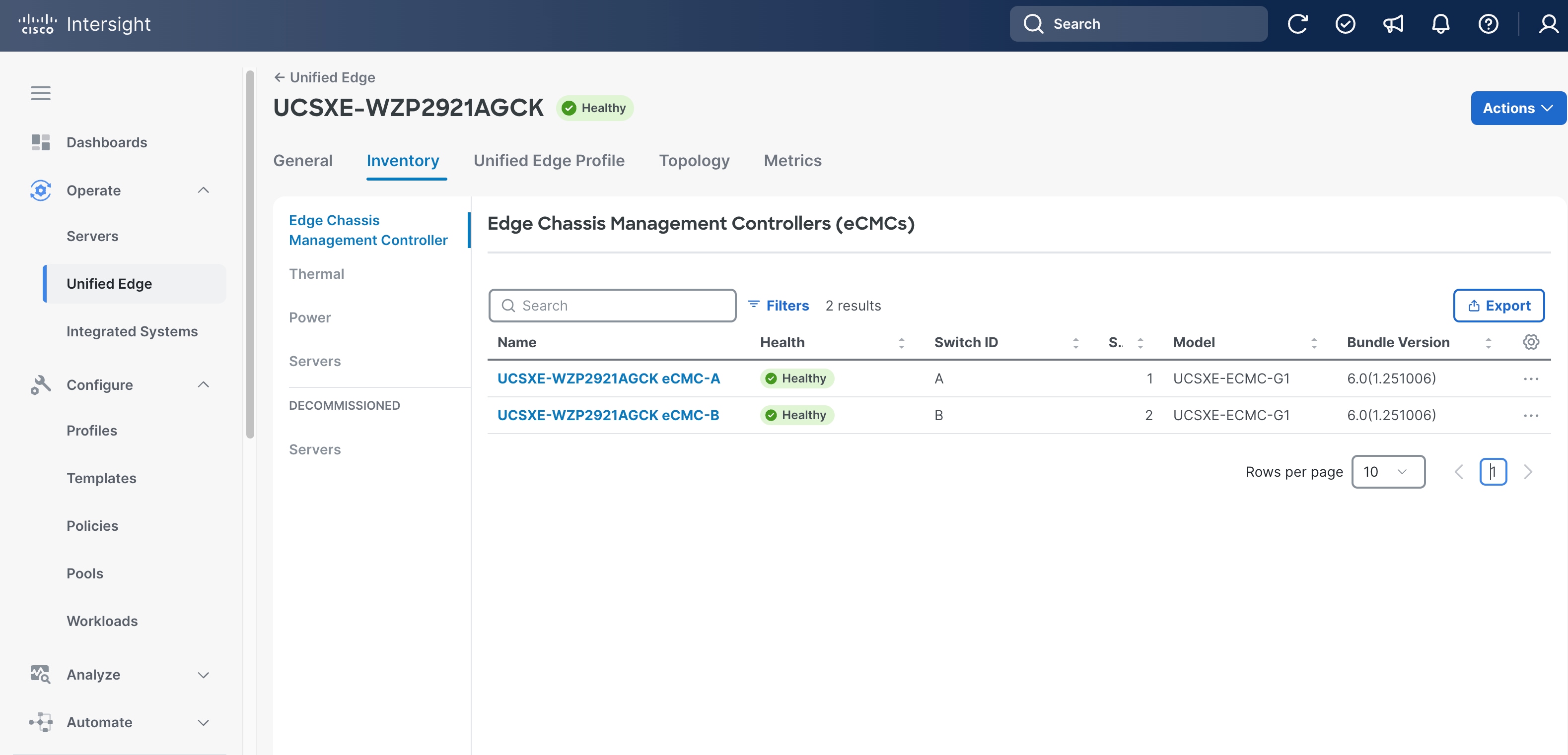
Step 10. When firmware upgrade is complete, go to Operate > Unified Edge, click the newly added UCS XE9305 device.
Step 11. Go to the Inventory tab, click Edge Chassis Management Controller. Verify both eCMC controllers are in Healthy status, and the Bundle Version column shows the right release.
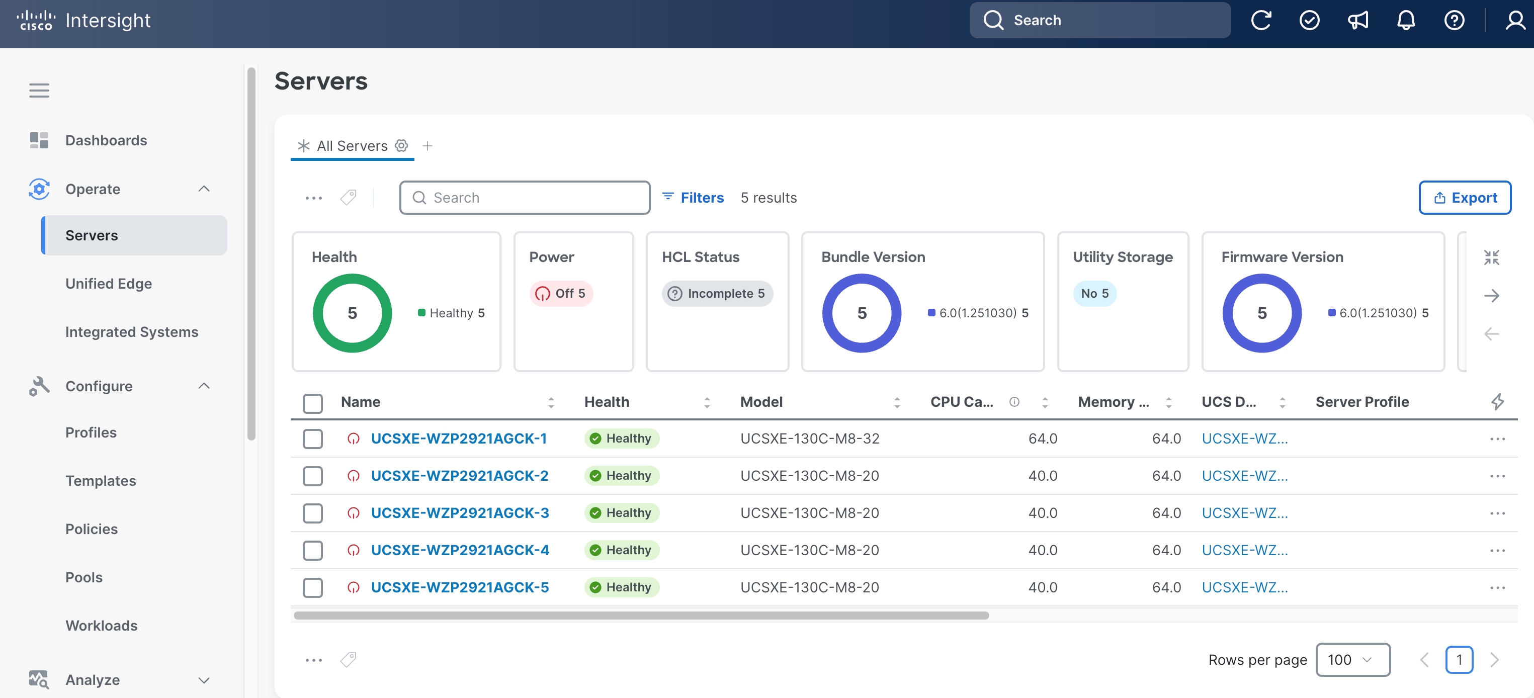
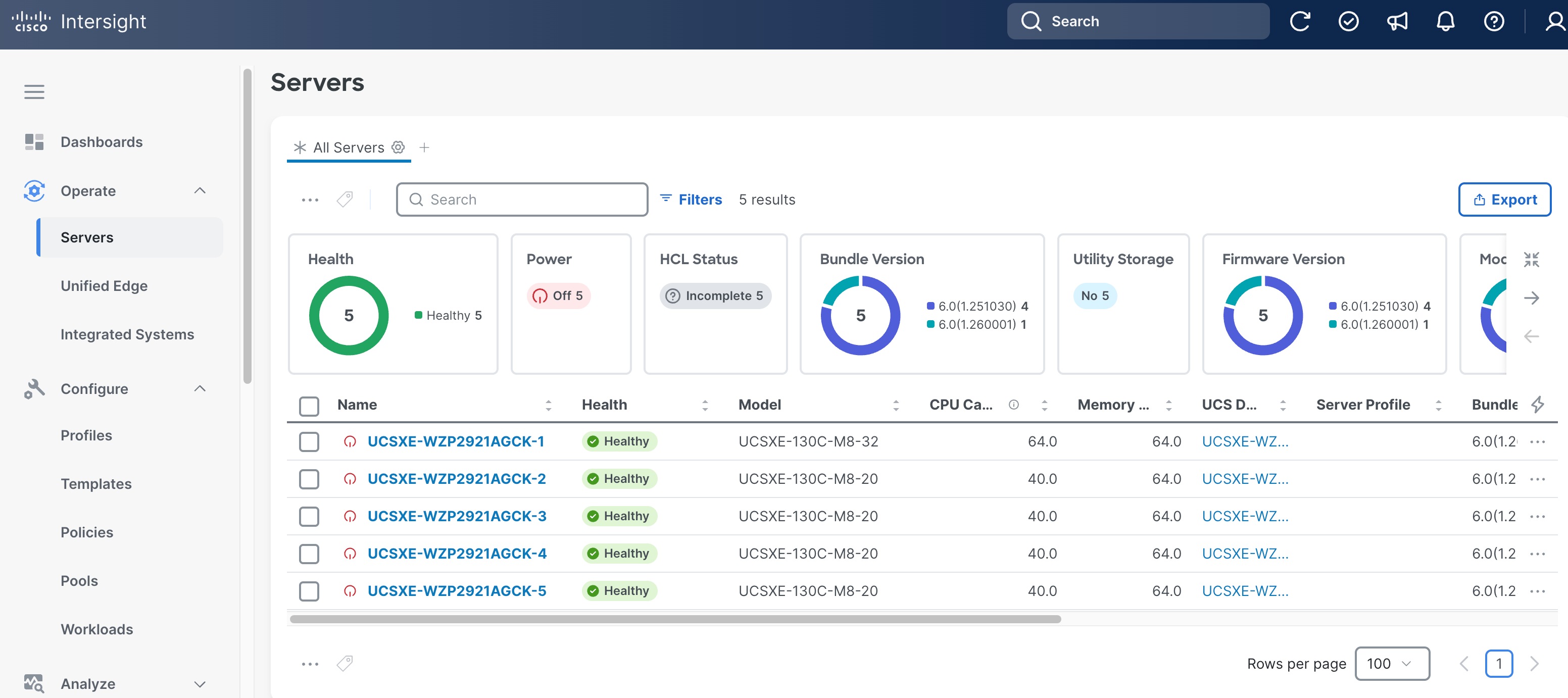
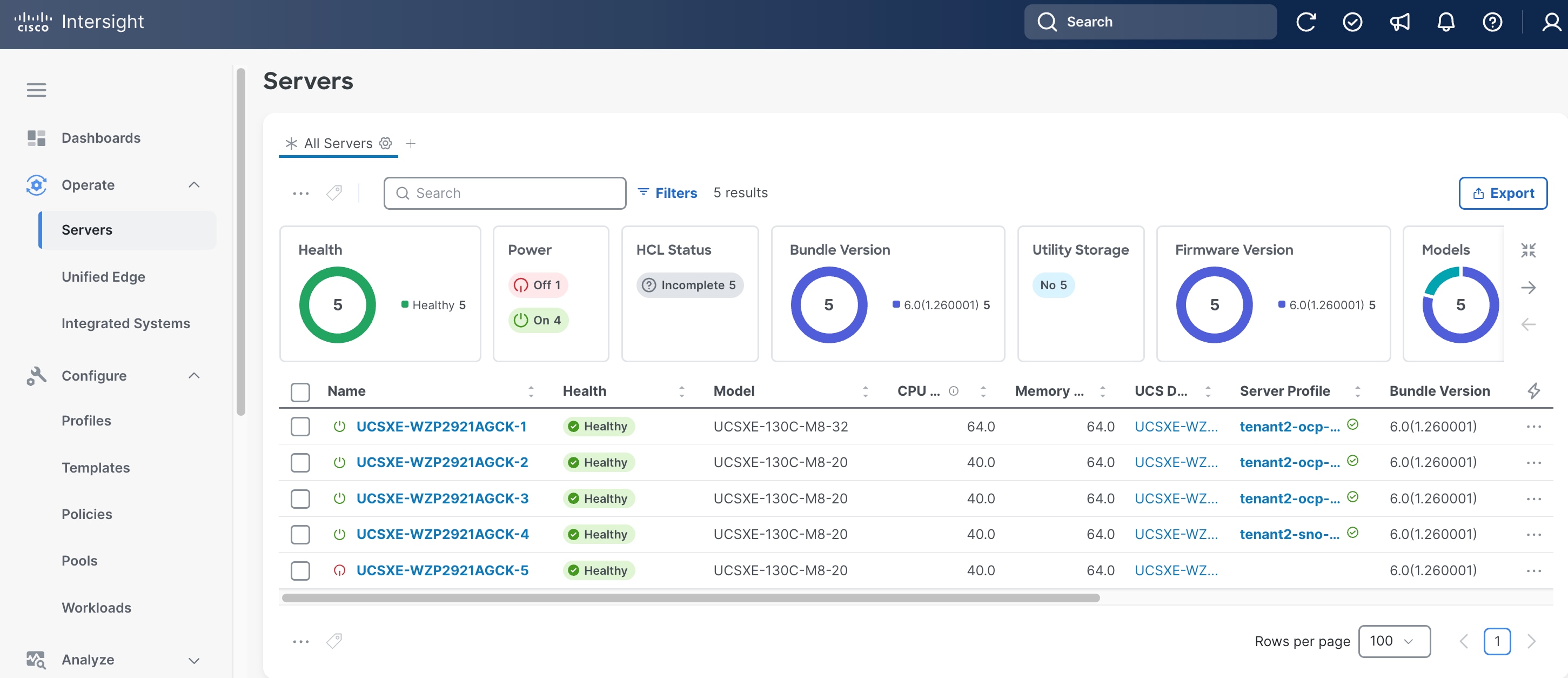
Step 12. Go to Operate > Servers, verify the UCS XE130c M8 servers on the newly added UCS XE9305 device are discovered.
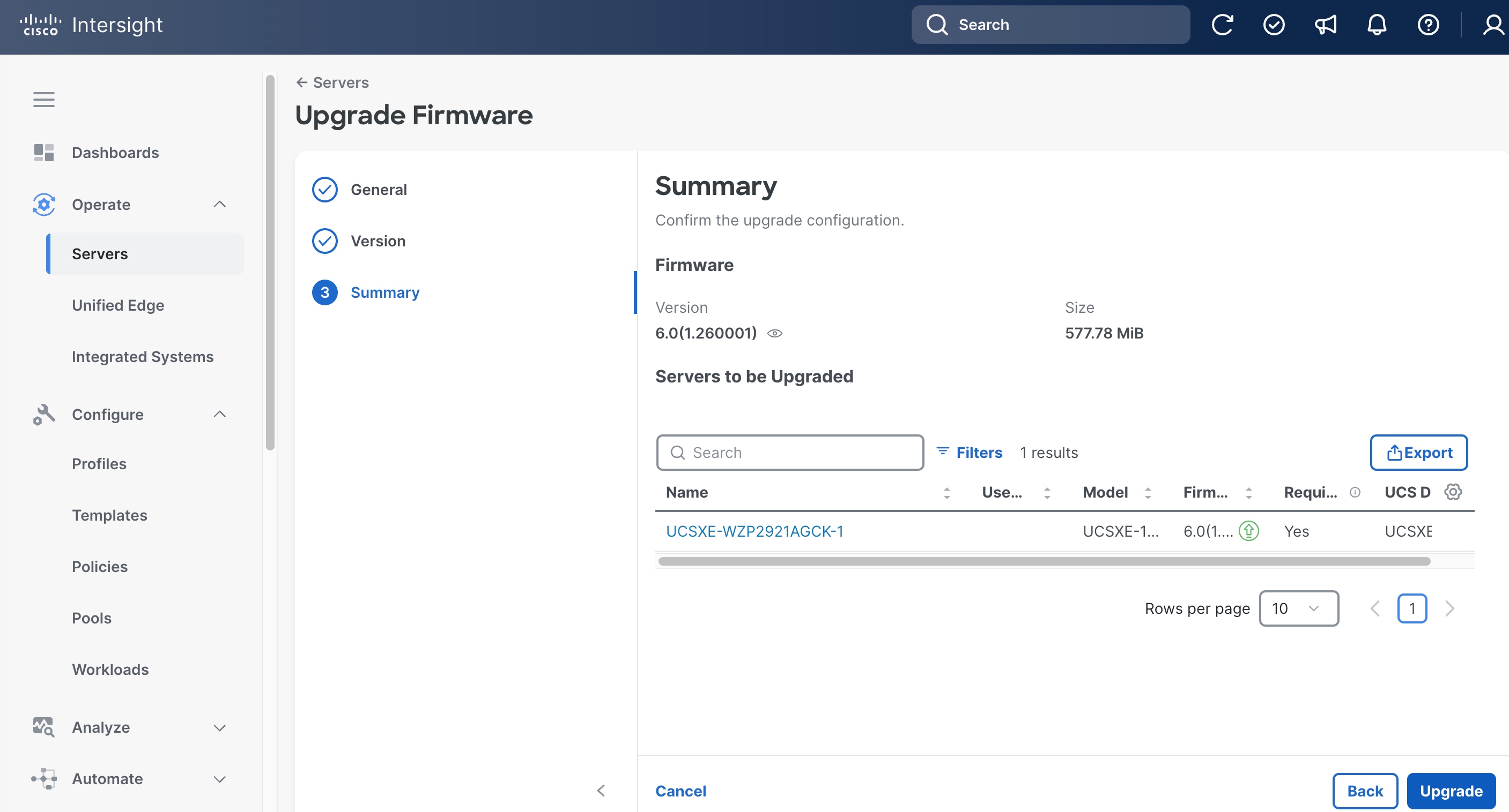
Procedure 3. Upgrade Server Firmware (Optional)
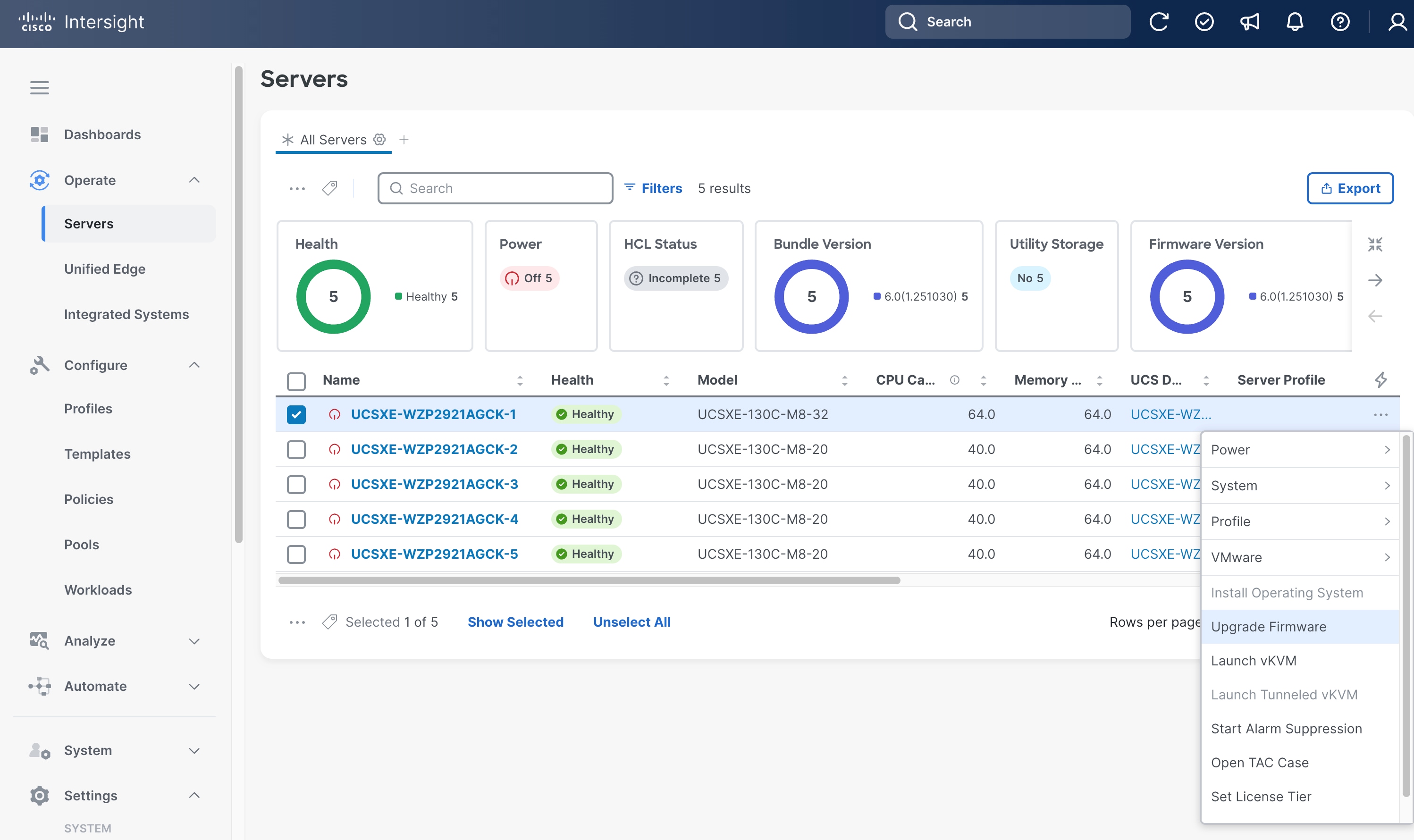
Step 1. Go to Operate > Servers, select a UCS XE130c M8 server, click the ellipses (…) at the end of the row. From the drop-down list, select Upgrade Firmware.
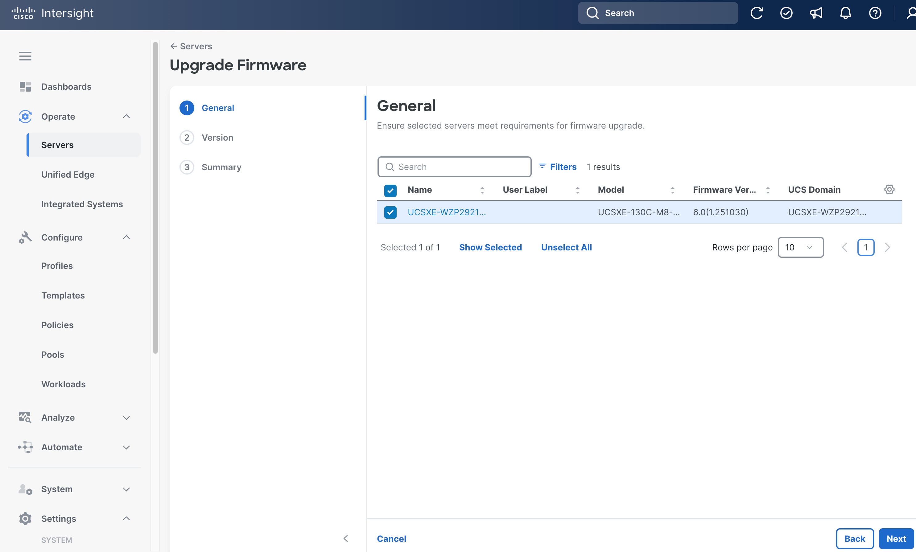
Step 2. On the General page, click Next.
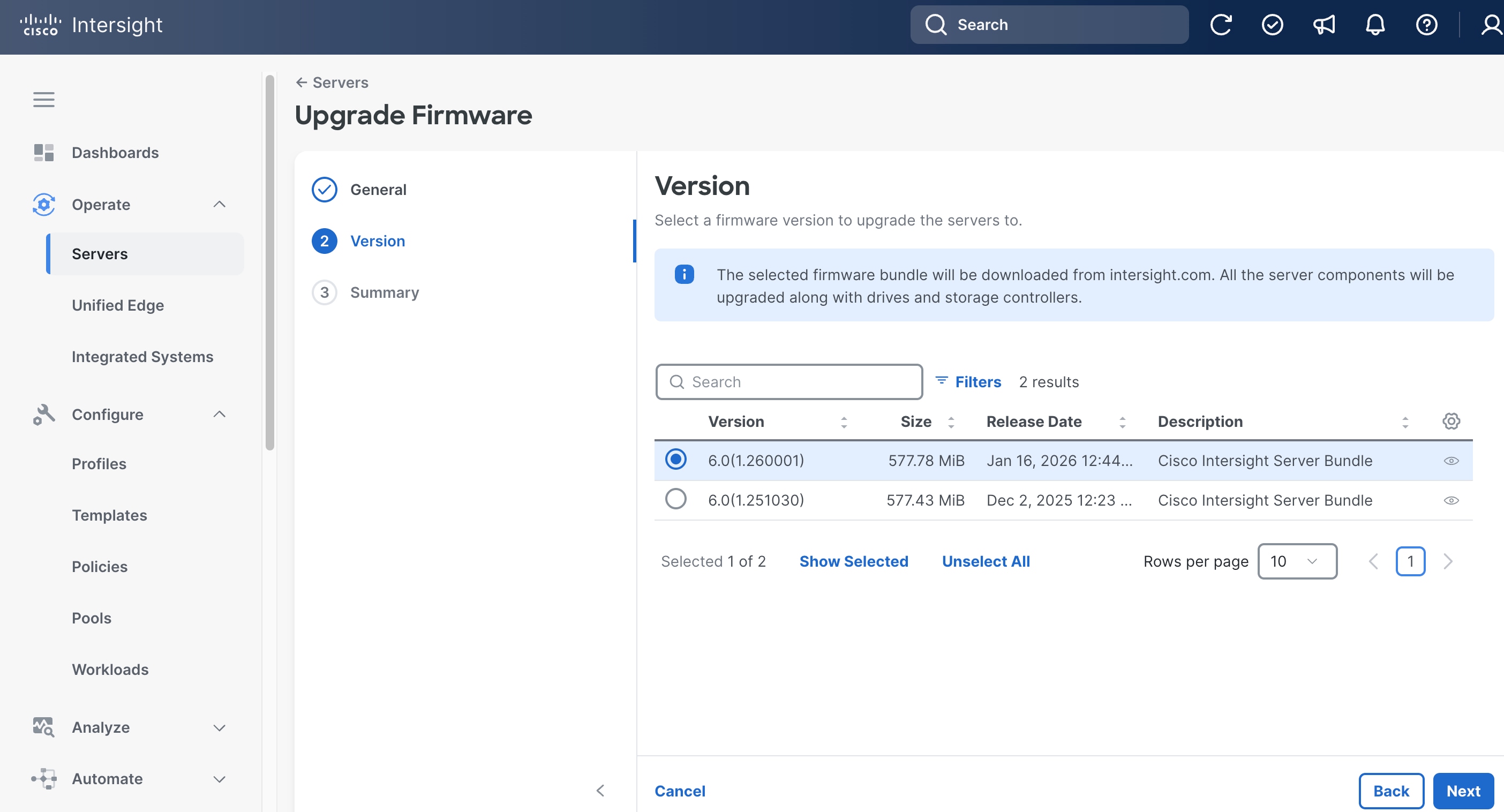
Step 3. On the Version page, choose the target release.
Step 4. Click Next.
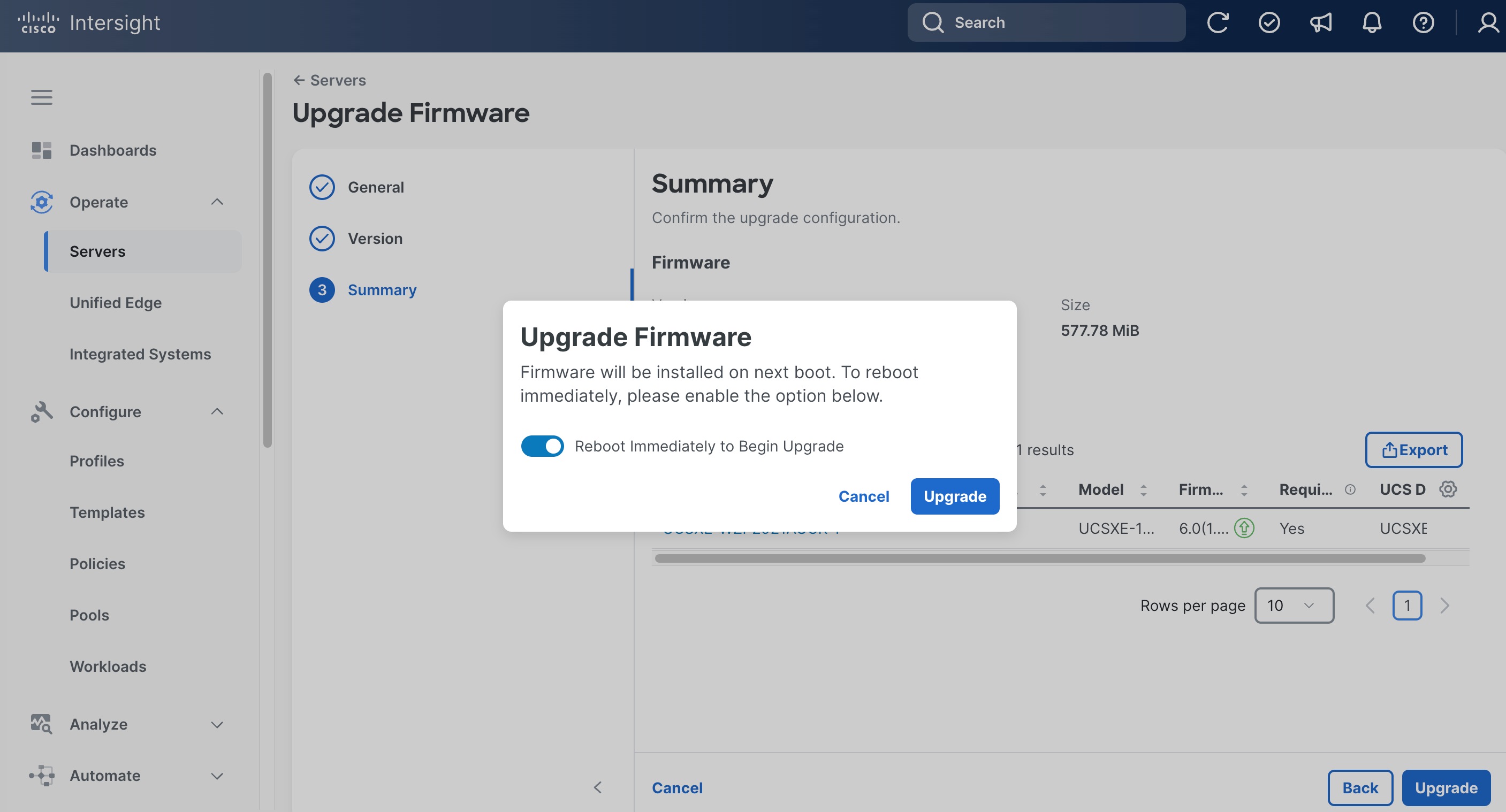
Step 5. On the Summary page, click Upgrade.
Step 6. In the pop-up window, toggle the switch to enable Reboot Immediately to Begin the Upgrade, and click Upgrade.
Step 7. Click the checkmark icon at upper-right corner to monitor the status of server firmware upgrade request. It will take a while for the requests Upgrade Firmware and Server Discovery to reach the Success status.
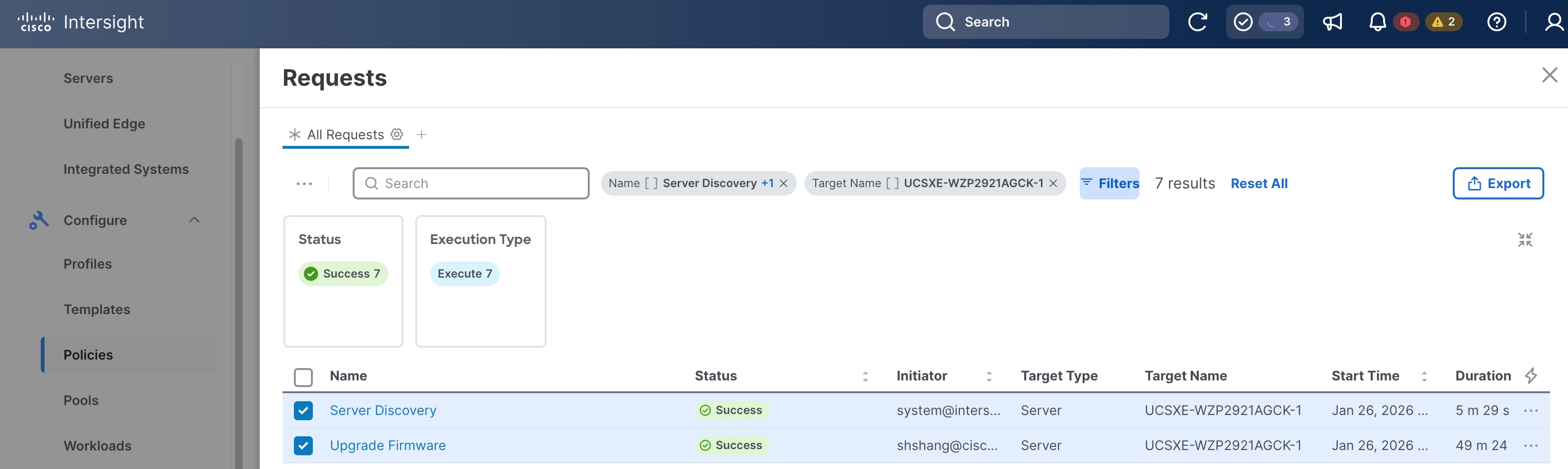
Step 8. Repeat Step 1 – Step 7 to upgrade the firmware for all discovered UCS XE130c M8 servers.
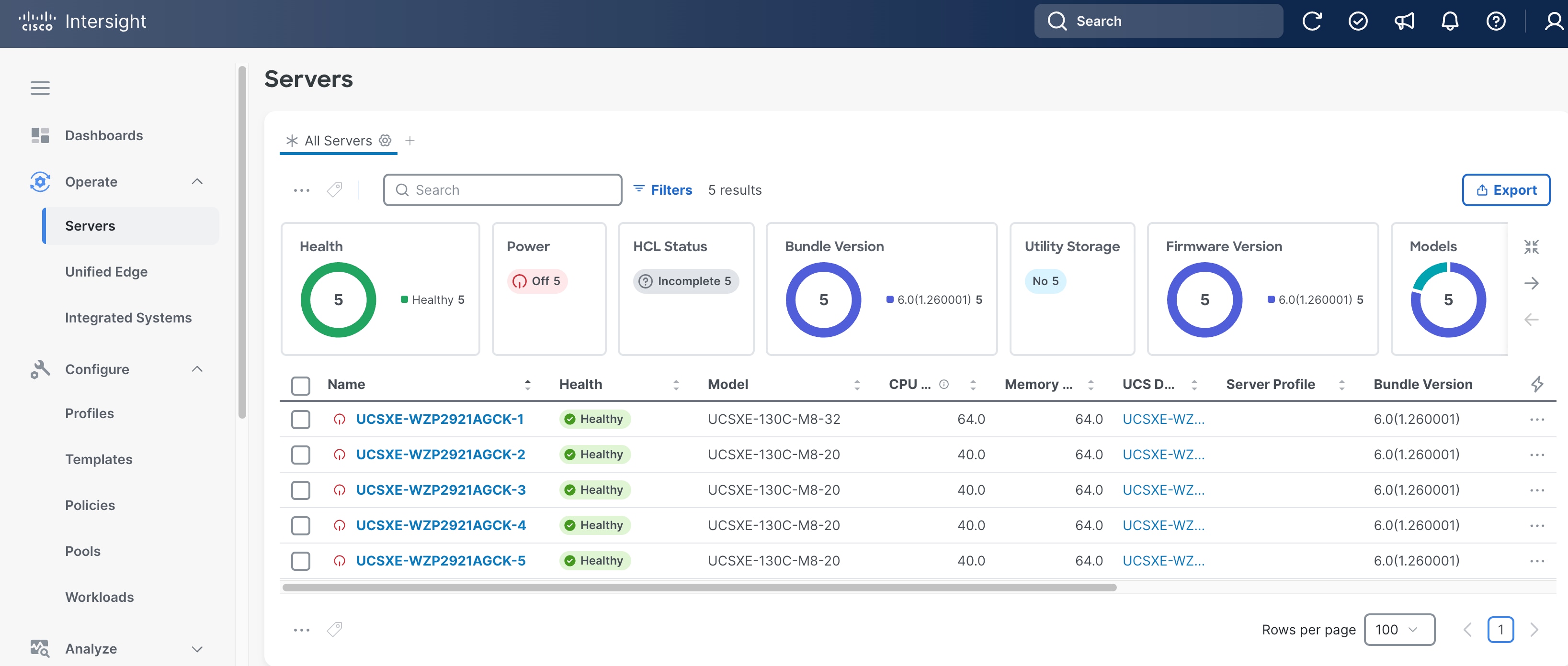
Step 9. Go to Operate > Servers. Verify the Bundle Version shows the correct release number, and the Health status is Healthy for all servers.
Build the Unified Edge Profile Template
A Unified Edge profile is derived from a Unified Edge profile template and is used to configure a Cisco UCS XE9305 chassis through reusable policies. It includes the port and port-channel settings on the eCMCs and provisions the required VLANs. Unified Edge related policies can be attached during profile template creation or added later.
Table 2 lists the policies for Unified Edge that are used in the validated design. All policies are created in the Tenant2 organization and use tenant2 as prefix.
Table 2. Unified Edge policies
| Unified Edge Policy |
Name |
Notes |
| Chassis Configuration |
||
| Thermal |
tenant2-thermal |
Manage temperature based on performance and environment needs. |
| Power |
tenant2-chassis-power |
Control power consumption and recovery after outages |
| Switch Configuration |
||
| VLAN |
tenant2-ecmc-vlan |
Defines the VLANs configured and allowed on eCMCs. |
| Port |
tenant2-ecmc-A-port-channel |
Configure port types and port roles for each eCMC uplink port. This policy for eCMC-A. |
|
|
tenant2-ecmc-B-port-channel |
Configure port types and port roles for each eCMC uplink port. This policy for eCMC-B. |
| Link Aggregation |
tenant2-uplink-aggregation |
Defines LACP settings for eCMC uplink bond interfaces. |
|
|
|
|
| System QoS |
tenant2-qos |
Defines the system-wide QoS classes and bandwidth/priority settings for traffic flows. |
| Switch Control |
tenant2-switch-control |
Global settings at eCMC level to enable and disable Jumbo frames on the embedded switches. |
| Management Configuration |
||
| NTP |
tenant2-ntp |
Specifies NTP servers and time settings |
| Network Connectivity |
tenant2-network-conn-1 |
Defines management network settings, for example, DNS. |
| Local User |
tenant2-local-user |
Creates and manages local user accounts and role-based access on the managed devices. |
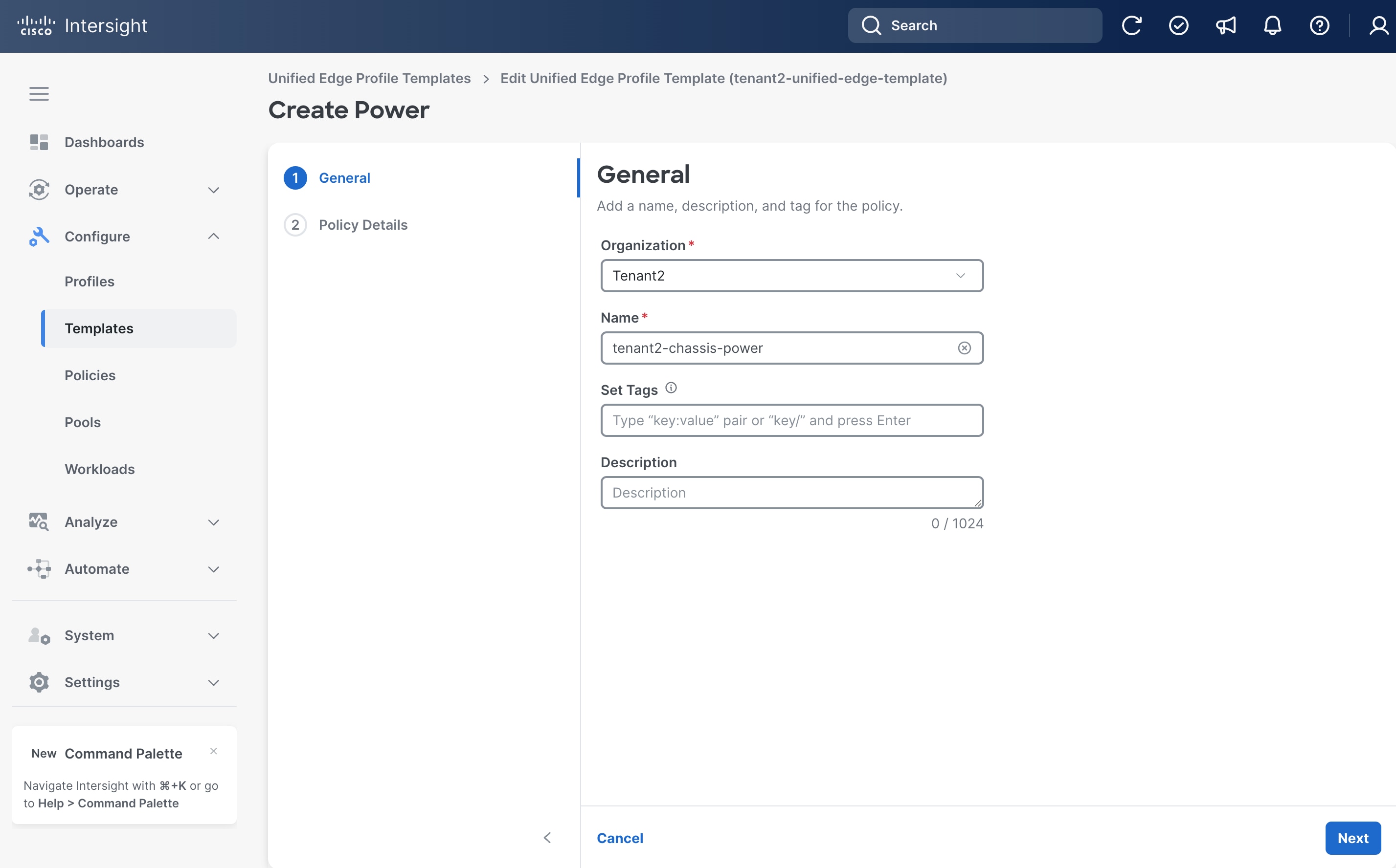
Procedure 4. Configure Power Policy
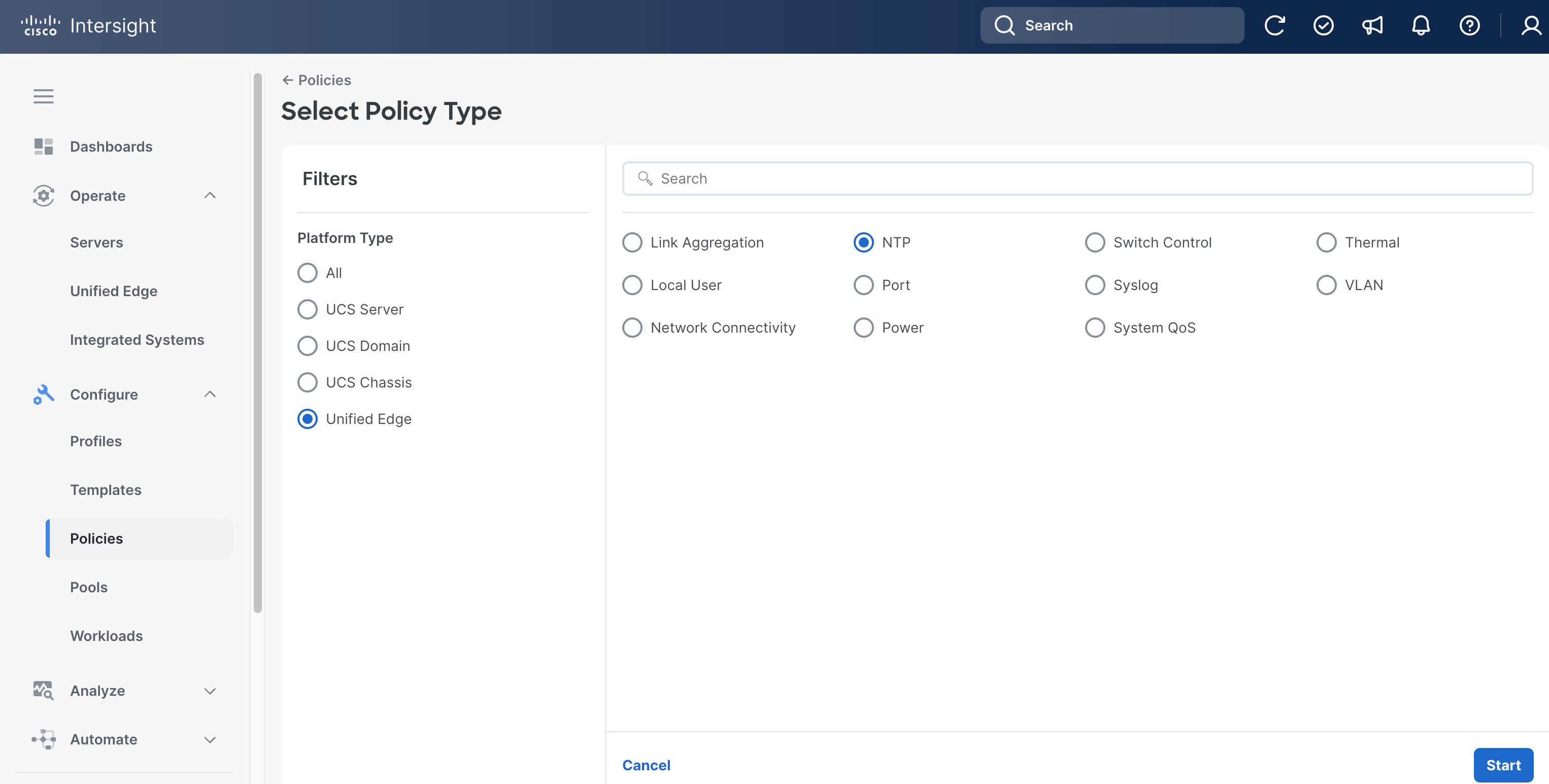
Step 1. Go to Configure > Policies. Click Create Policy.
Step 2. Click Unified Edge in the Filters section, then select Power.
Step 3. Click Start.

Step 4. On the General page, select the correct Organization, for example, Tenant2.
Step 5. Provide a Name for the policy, for example, tenant2-chassis-power.
Step 6. (Optional) Provide Tags and Description.
Step 7. Click Next.
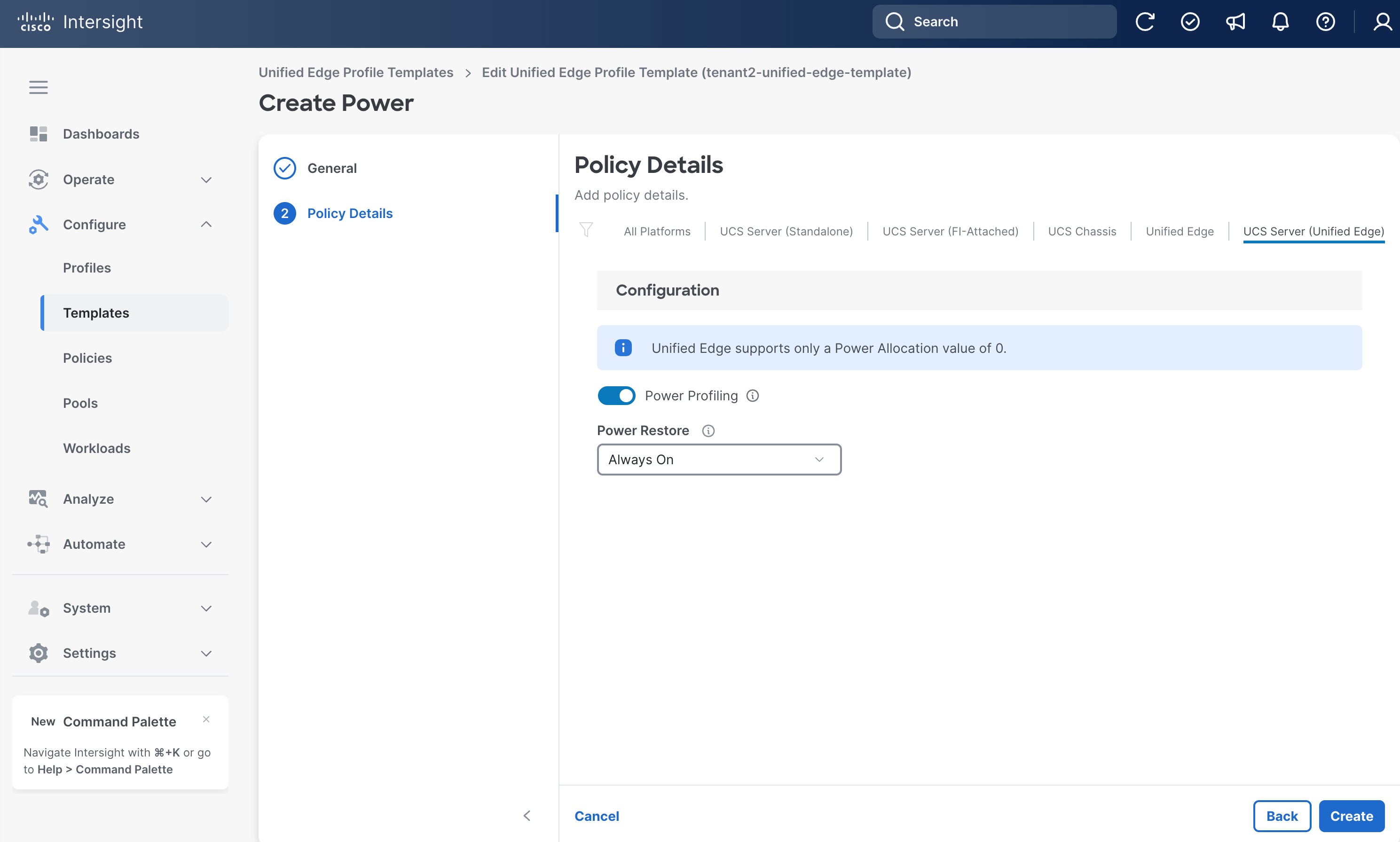
Step 8. On the Policy Details page, set a Power Restore option, for example, Always On.
Step 9. Click Create.
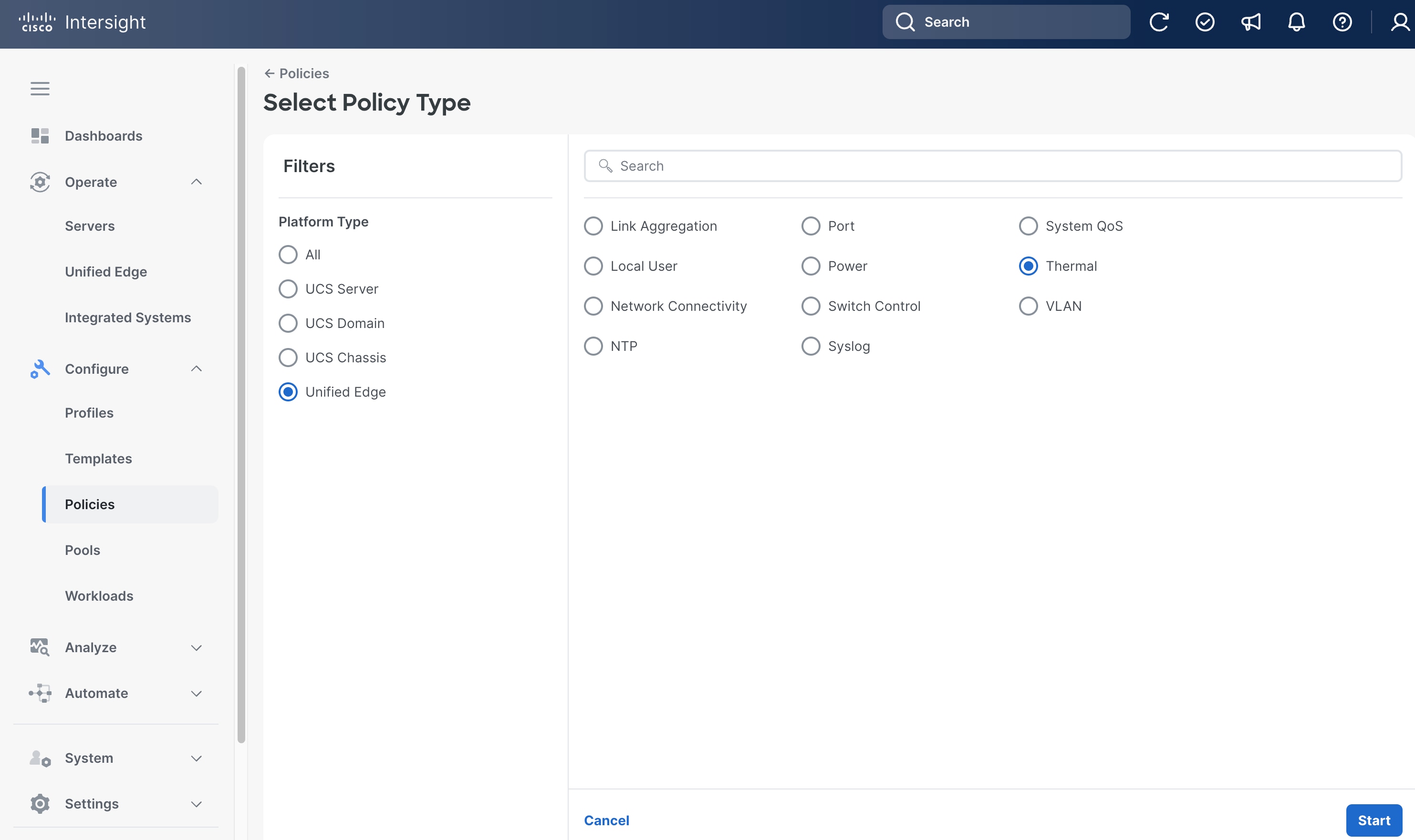
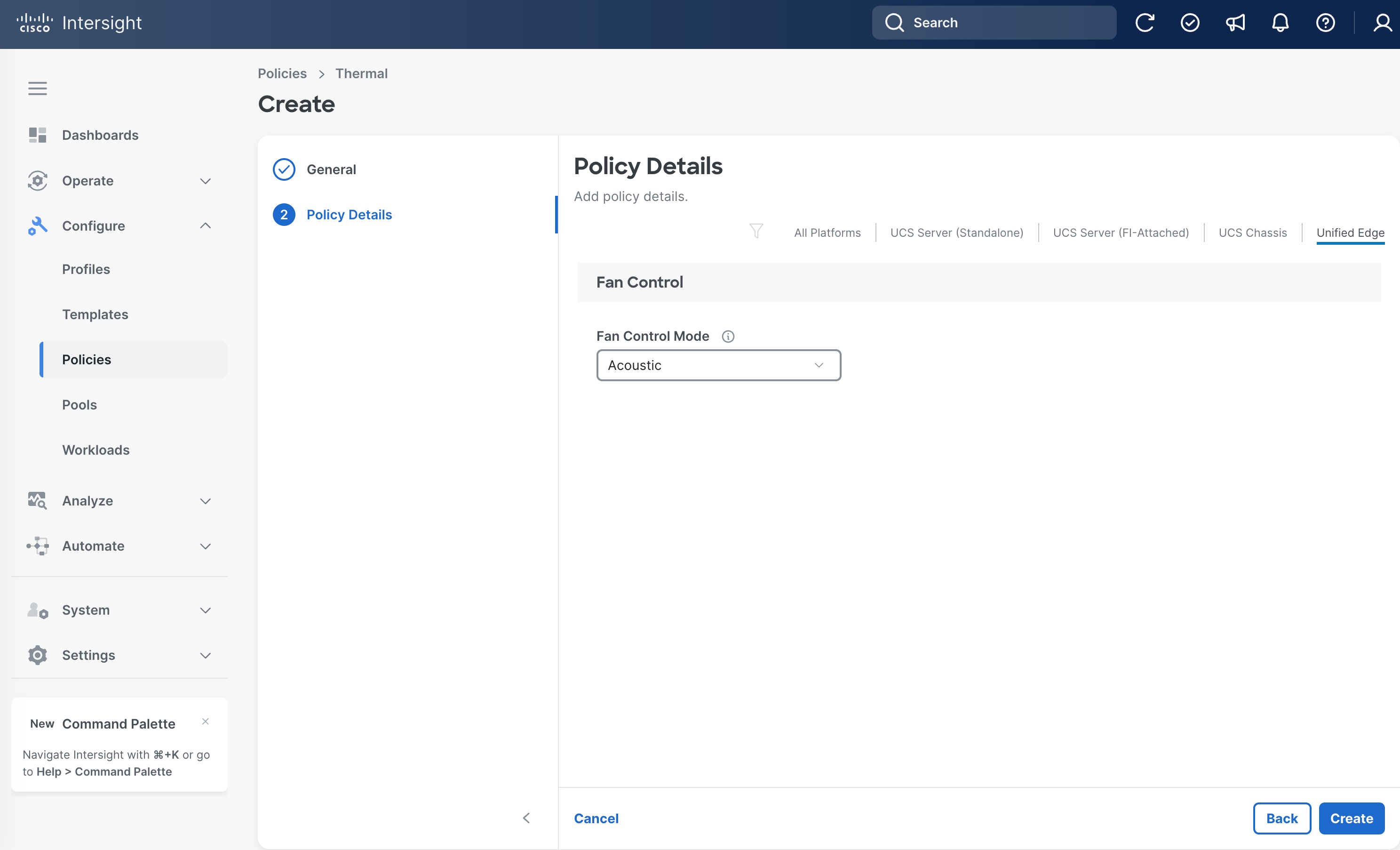
Procedure 5. Configure Thermal Policy
Step 1. Go to Configure > Policies. Click Create Policy.
Step 2. Click Unified Edge in the Filters section, then select Thermal.
Step 3. Click Start.
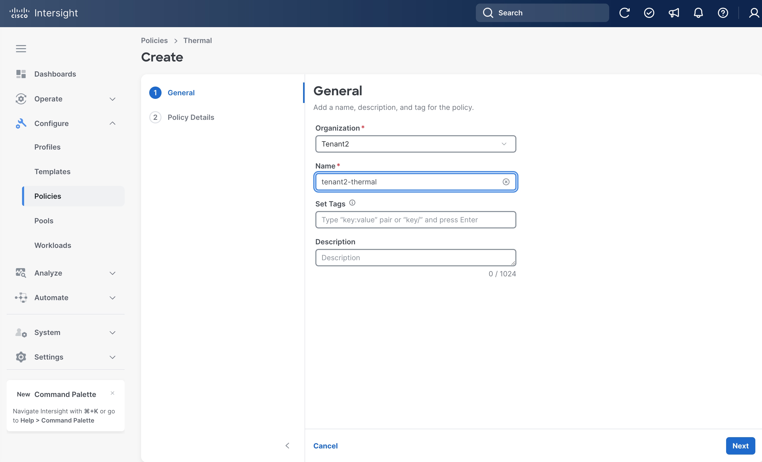
Step 4. On the General page, select the correct Organization, for example, Tenant2.
Step 5. Provide a name for the policy, for example, tenant2-thermal.
Step 6. (Optional) Provide Tags and Description.
Step 7. Click Next.
Step 8. On the Policy Details page, click Unified Edge.
Step 9. Select the Fan Control Mode, for example, Acoustic.
Step 10. Click Create.
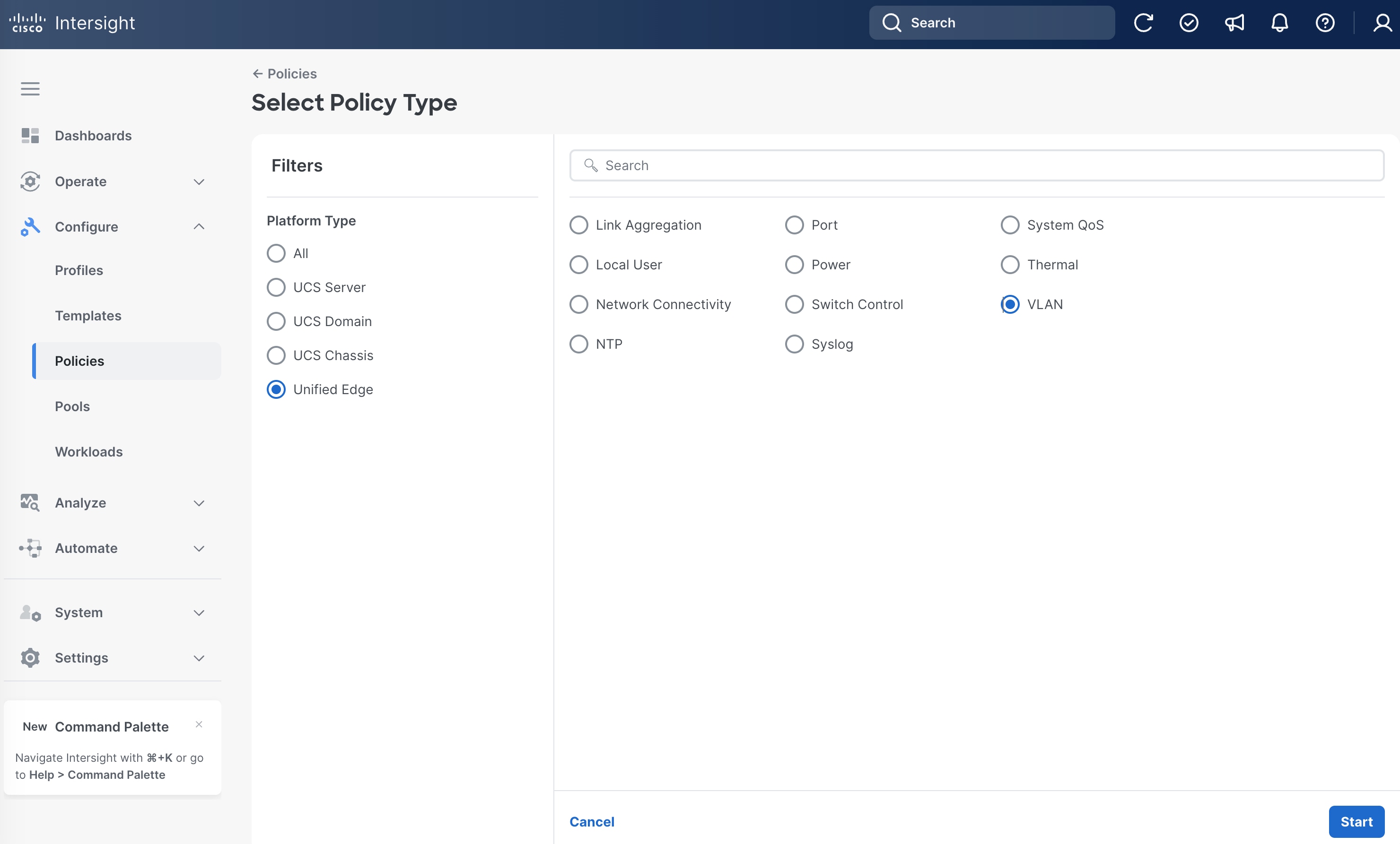
Procedure 6. eCMC VLAN Configuration
Step 1. Go to Configure > Policies. Click Create Policy.
Step 2. Click Unified Edge in the Filters section, then select VLAN.
Step 3. Click Start.
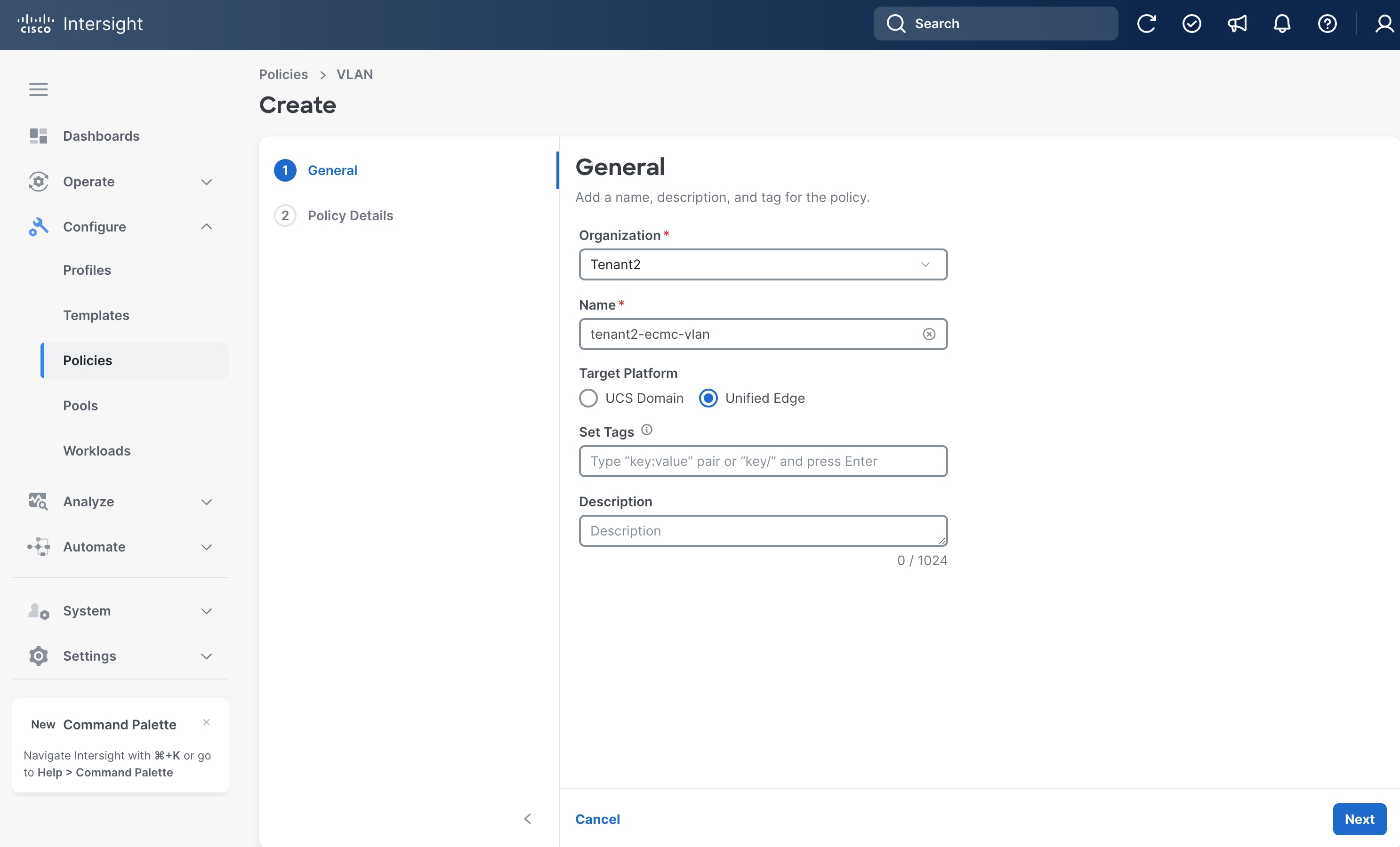
Step 4. On the General page, select the correct Organization, for example, Tenant2.
Step 5. Provide a name for the policy, for example, tenant2-ecmc-vlan.
Step 6. Select Unified Edge as the Target Platform.
Step 7. (Optional) Provide Tags and Description.
Step 8. Click Next.
Step 9. On the Policy Details page, click Add VLANs.
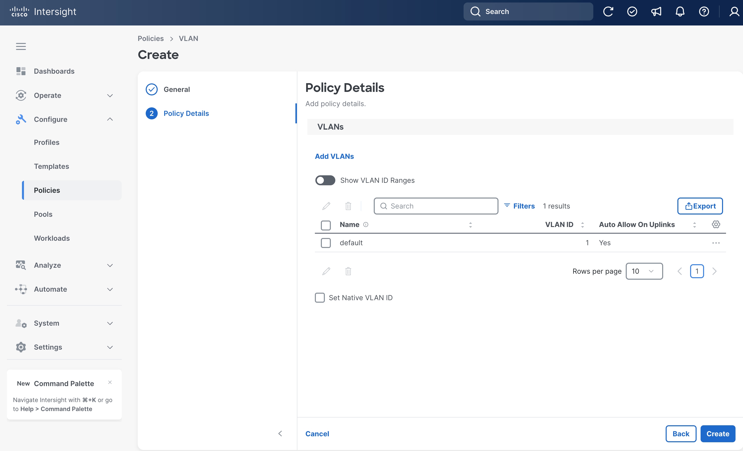
Step 10. Set Prefix as tenant2-ib-mgmt-vlan and VLAN ID to 1316.
Step 11. Click Add.
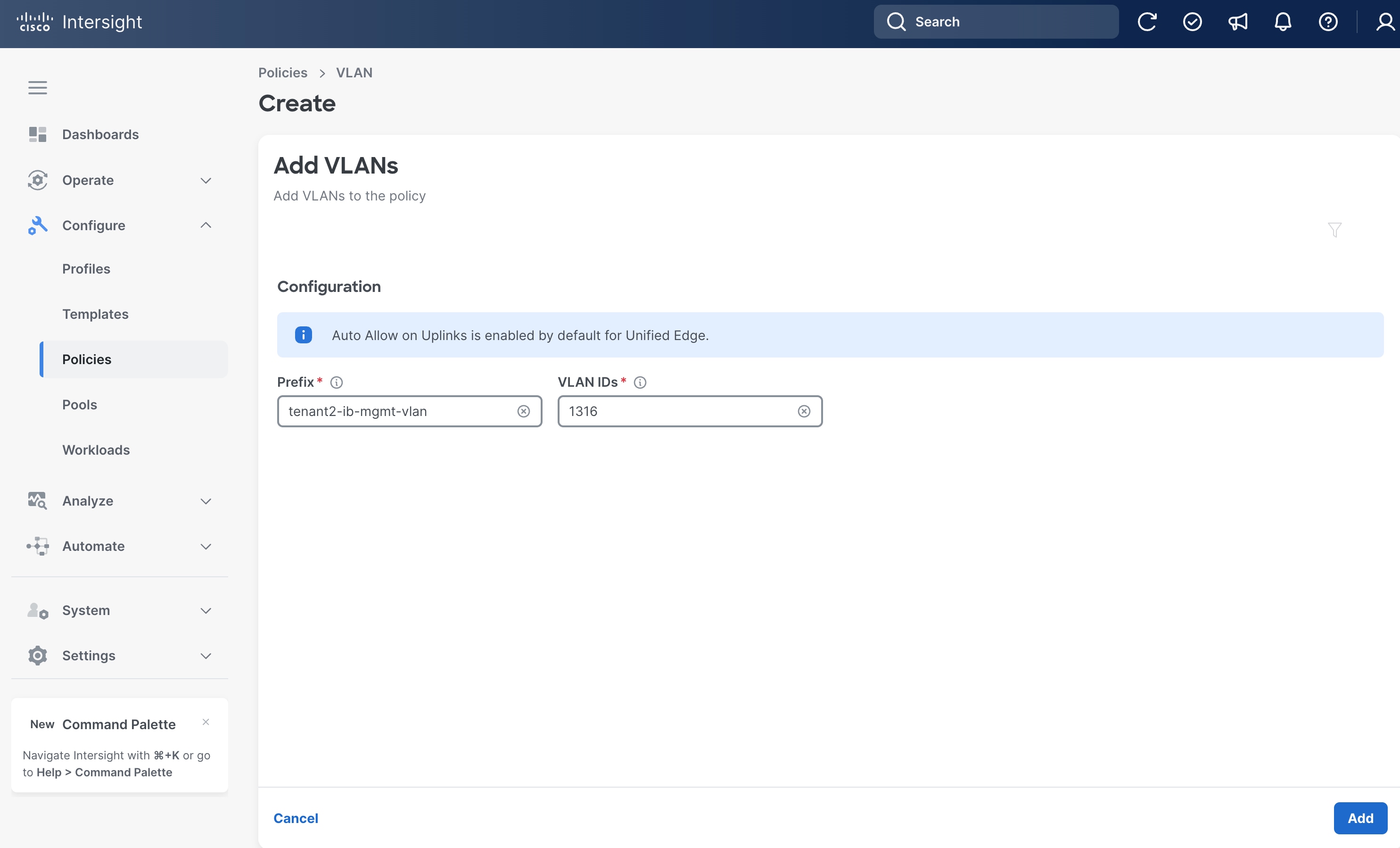
Step 12. Repeat Step 1 – Step 11 to add more VLANs.
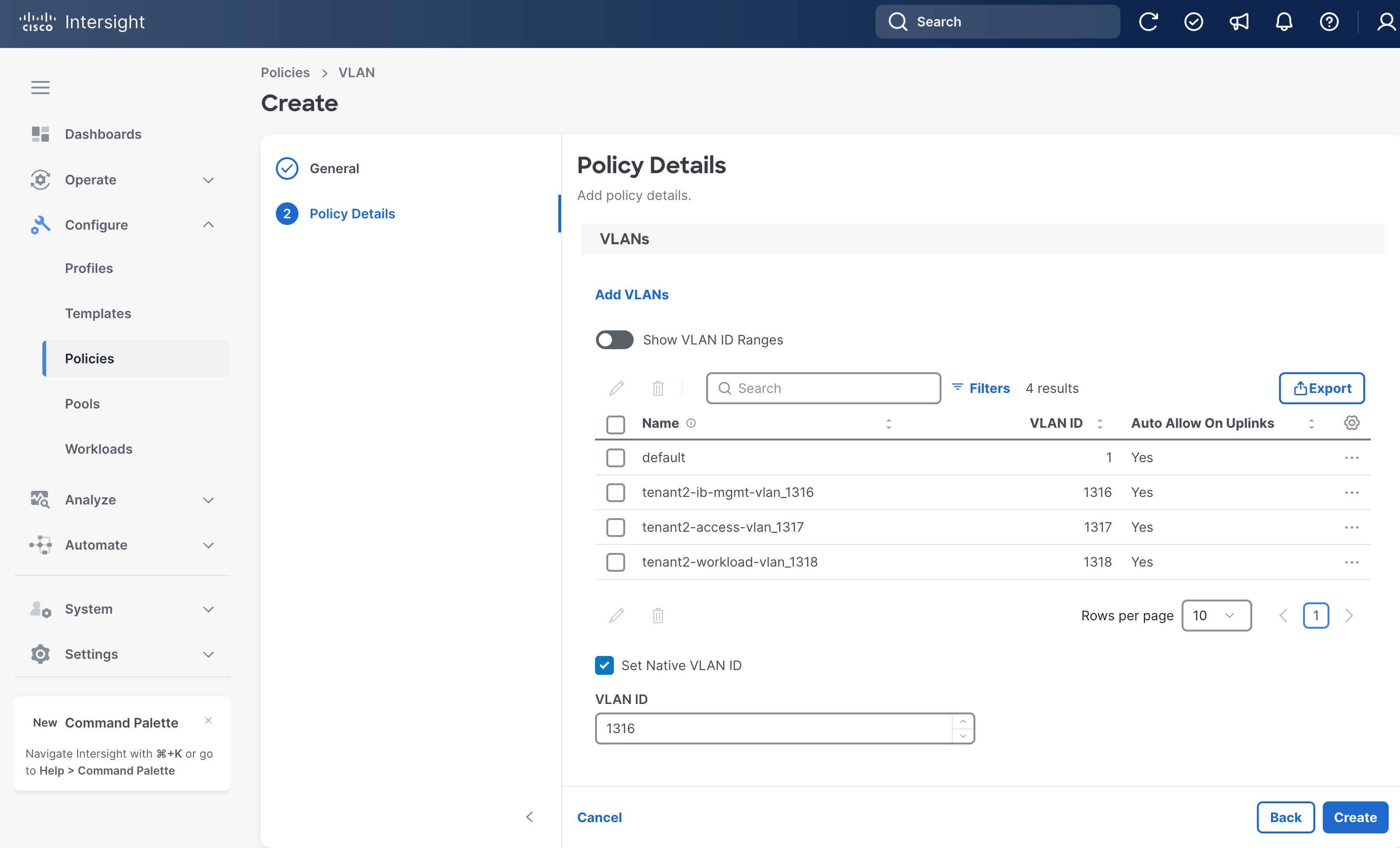
Step 13. From the Policy Details page, set VLAN 1316 as the Native VLAN ID.
Step 14. Click Create.
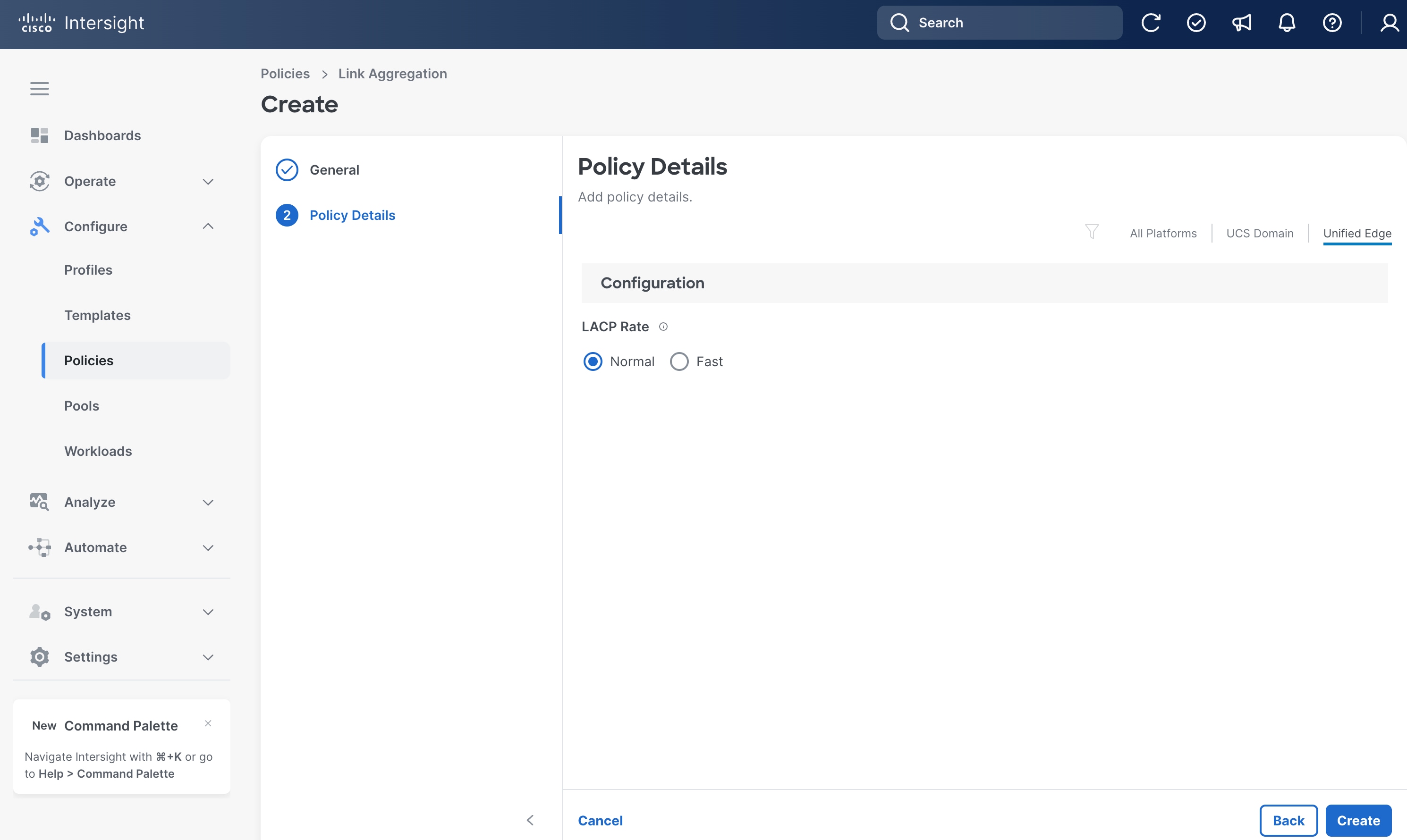
Procedure 7. Configure Link Aggregation Policy
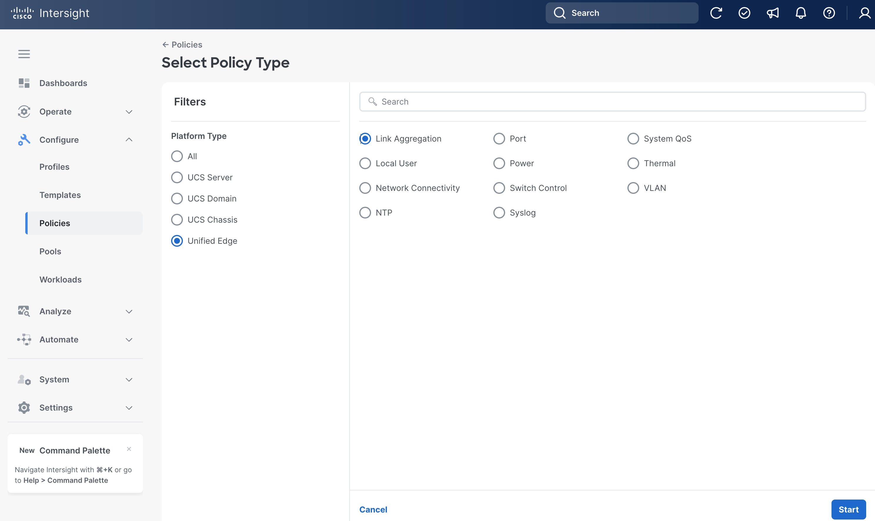
Step 1. Go to Configure > Policies. Click Create Policy.
Step 2. Click Unified Edge in the Filters section, then select Link Aggregation.
Step 3. Click Start.
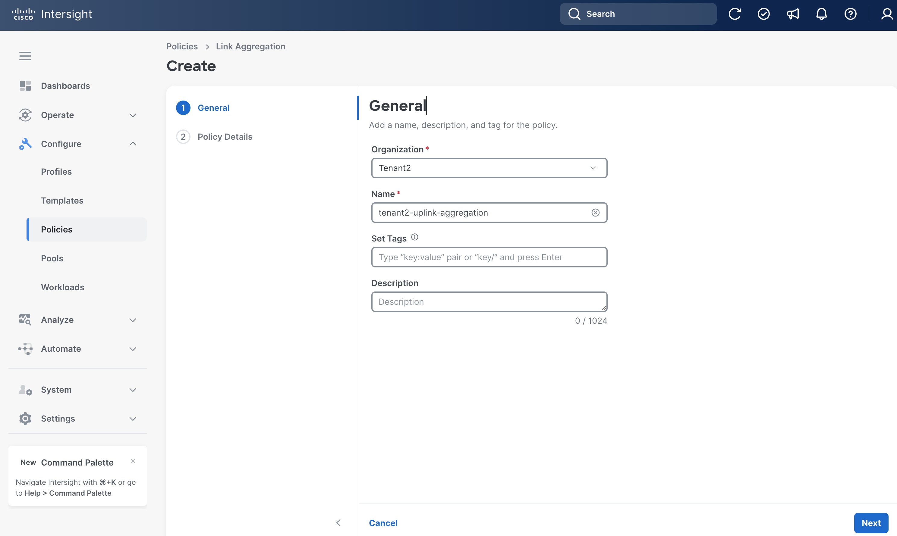
Step 4. On the General page, select the correct Organization, for example, Tenant2.
Step 5. Provide a Name for the policy, for example, tenant2-uplink-aggregation.
Step 6. (Optional) Provide Tags and Description.
Step 7. Click Next.
Step 8. On the Policy Details page, click Unified Edge.
Step 9. Leave LACP Rate at its default settings.
Step 10. Click Create.
Procedure 8. Configure Port Policy for eCMC A
Step 1. Go to Configure > Policies. Click Create Policy.
Step 2. Click Unified Edge in the Filters section, then select Port.
Step 3. Click Start.

Step 4. On the General page, select the correct Organization, for example, Tenant2.
Step 5. Provide a Name for the policy, for example, tenant2-ecmc-A-port-channel.
Step 6. Select Unified Edge as the Target Platform.
Step 7. For Unified Edge Model, keep the default value, which is UCSXE-eCMC-G1.
Step 8. (Optional) Provide Tags and Description.
Step 9. Click Next.

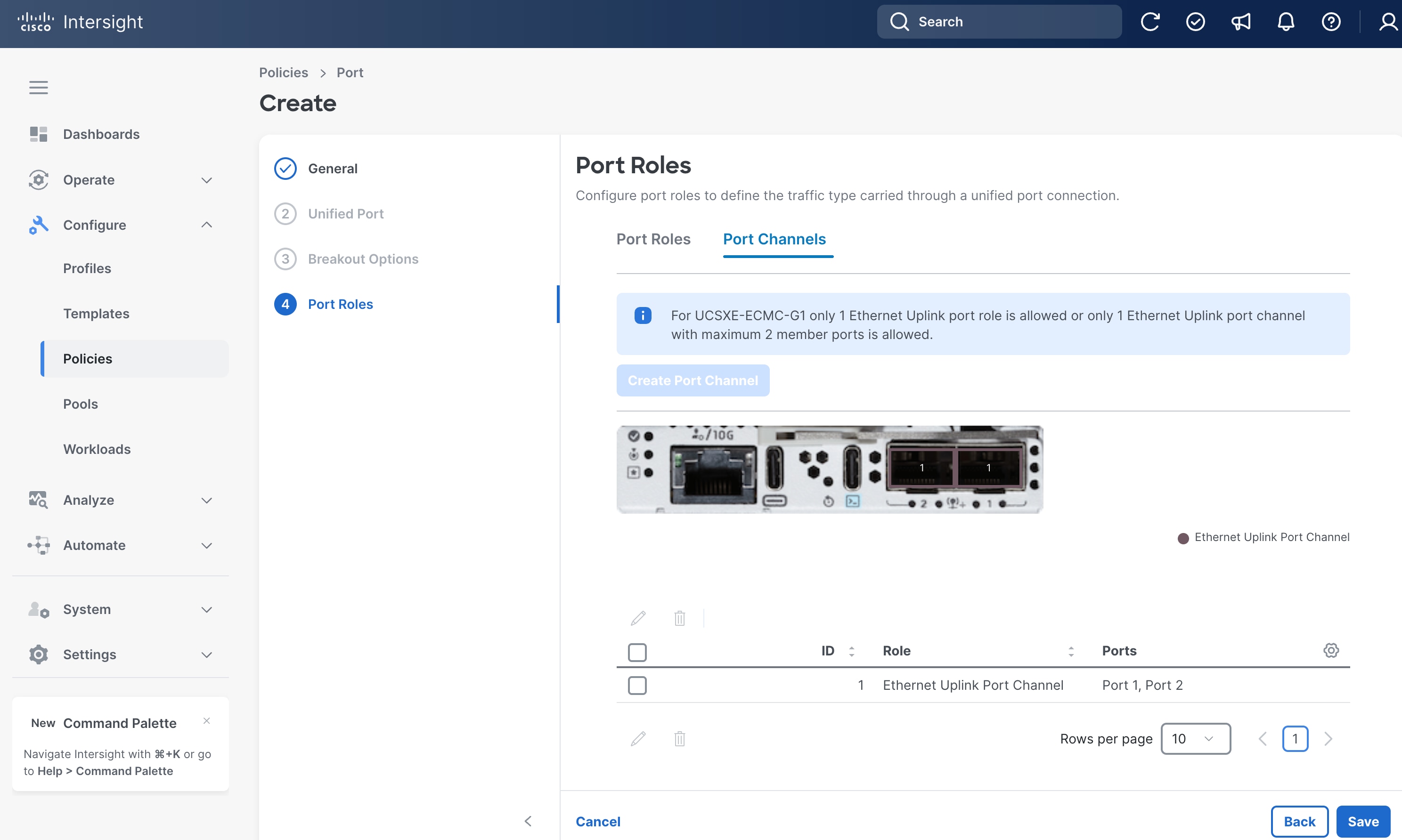
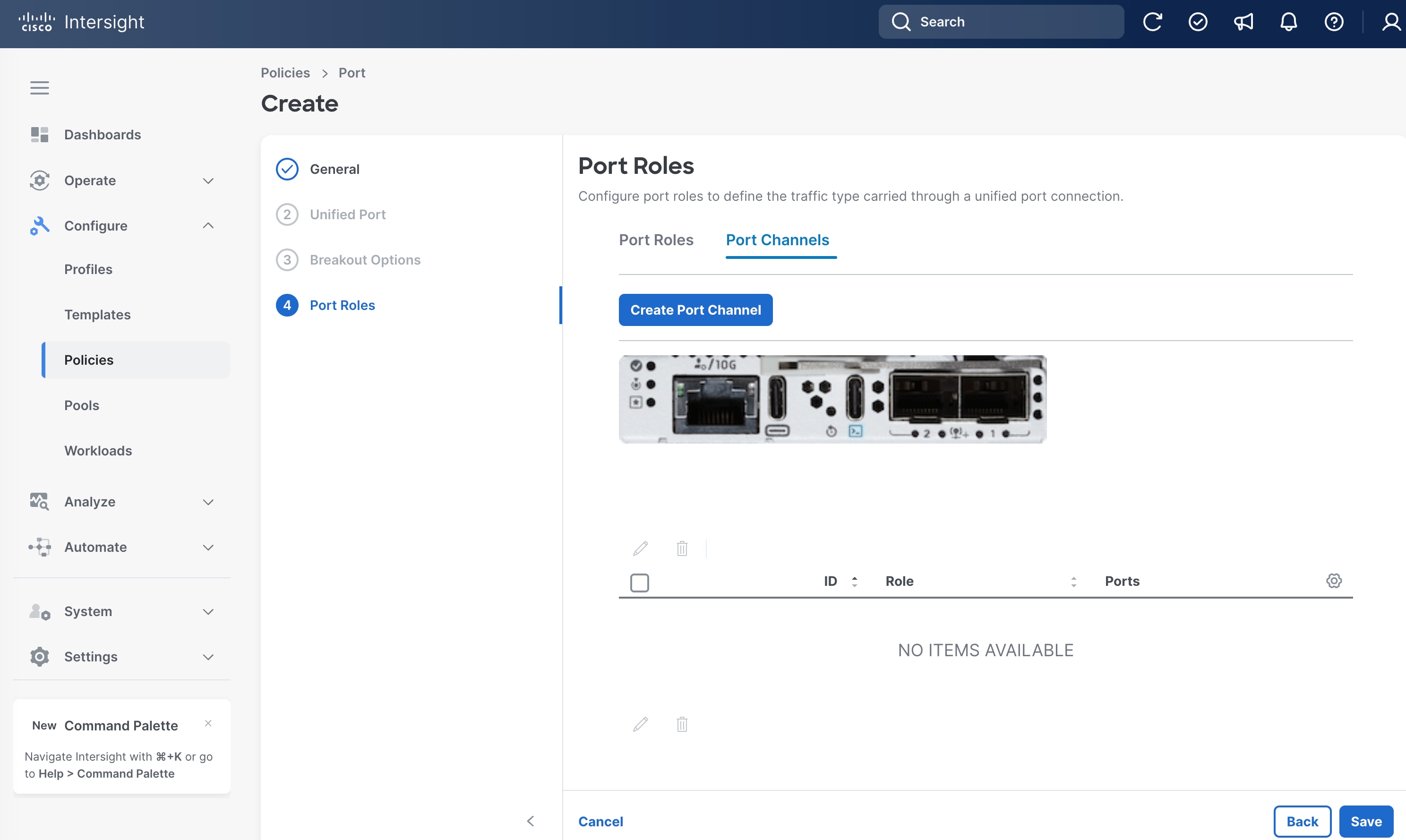
Step 10. On the Port Roles page, click Port Channels tab.
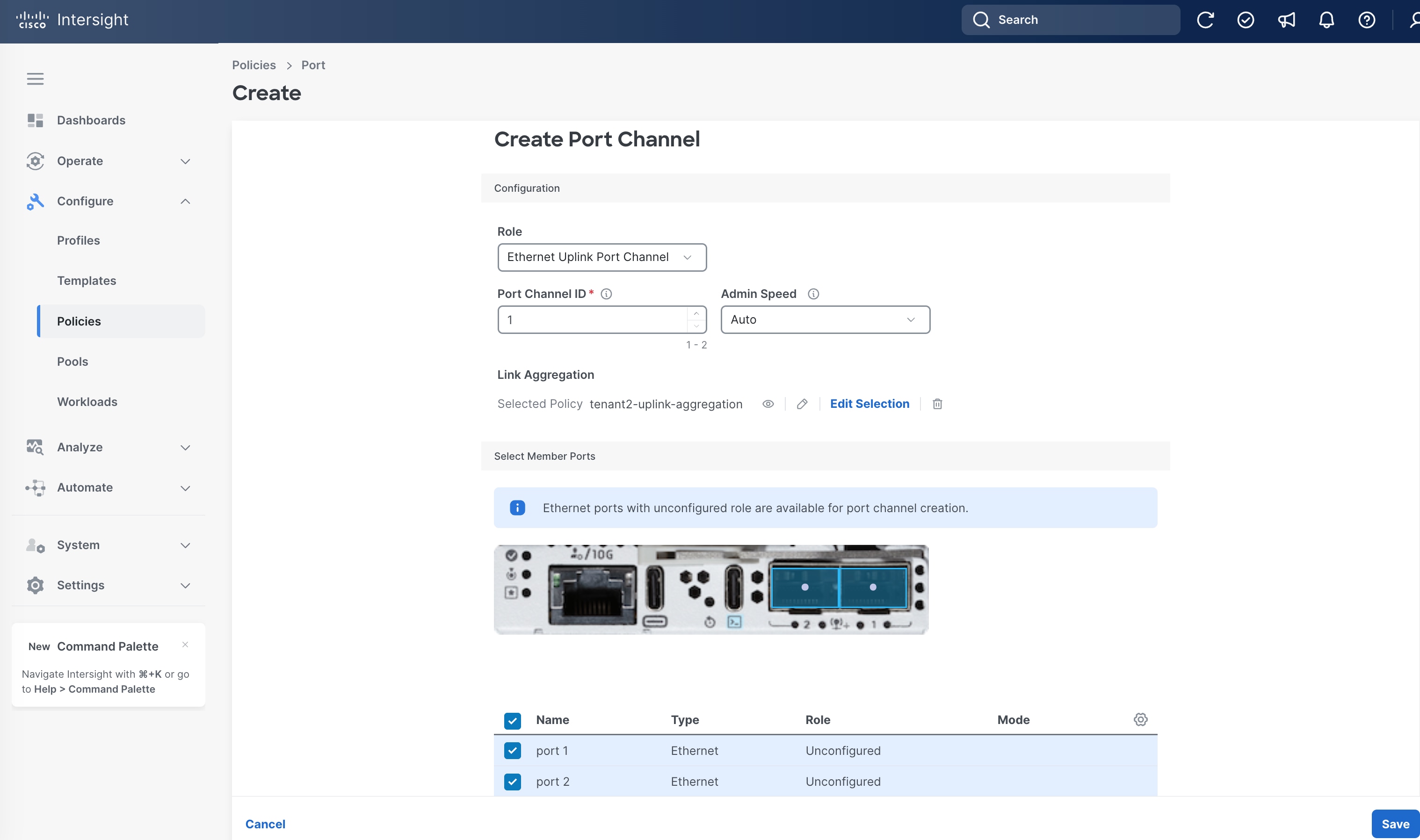
Step 11. Click Create Port Channel.

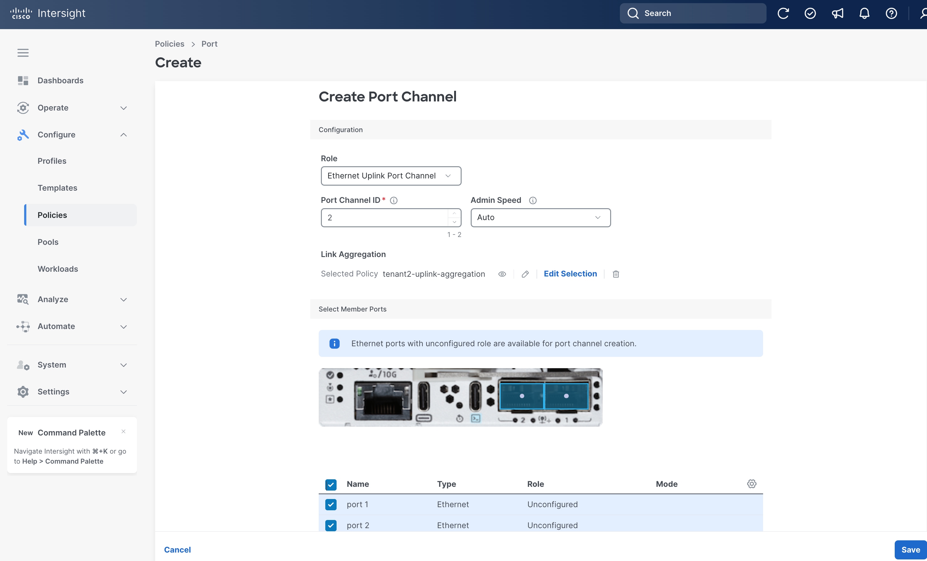
Step 12. On the Create Port Channel page, set Port Channel ID to 1.
Step 13. Under Link Aggregation, choose the Link Aggregation policy that is created in the previous step, for example, tenant2-uplink-aggregation.
Step 14. Select BOTH port1 and port2 toward the bottom of the page.
Step 15. Leave other fields at their default values.
Step 16. Click Save.
Step 17. Back to Port Roles page, click Save.
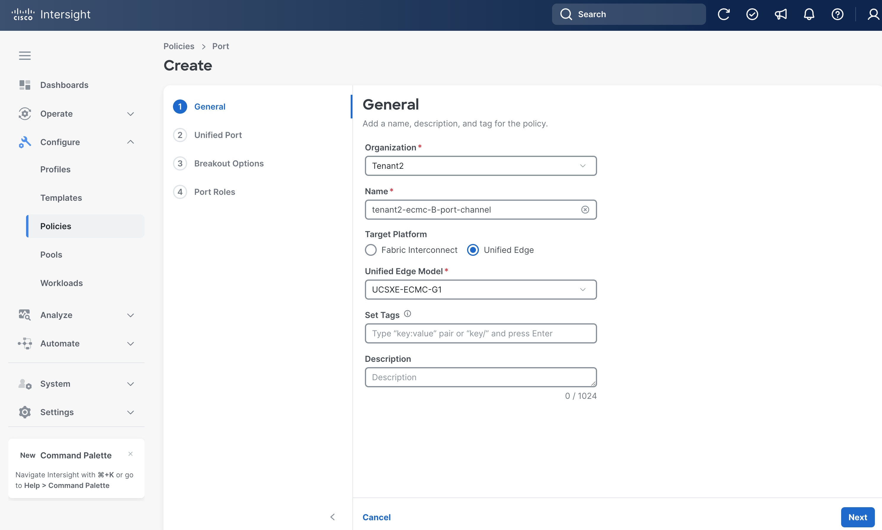
Procedure 9. Configure Port Policy for eCMC B
Step 1. Go to Configure > Policies. Click Create Policy.
Step 2. Click Unified Edge in the Filters section, then select Port.
Step 3. Click Start.

Step 4. On the General page, select the correct Organization, for example, Tenant2.
Step 5. Provide a Name for the policy, for example, tenant2-ecmc-B-port-channel.
Step 6. Select Unified Edge as the Target Platform.
Step 7. For Unified Edge Model, leave the default value, which is UCSXE-eCMC-G1.
Step 8. (Optional) Provide Tags and Description.
Step 9. Click Next.
Step 10. On the Port Roles page, click Port Channels tab.
Step 11. Click Create Port Channel.
Step 12. On the Create Port Channel page, set Port Channel ID to 2.
Step 13. Under Link Aggregation, choose the Link Aggregation policy that is created in the previous procedure, for example, tenant2-uplink-aggregation.
Step 14. Select BOTH port1 and port2 toward the bottom of the page.
Step 15. Leave other fields at their default values.
Step 16. Click Save.
Step 17. Back to Port Roles page, click Save.

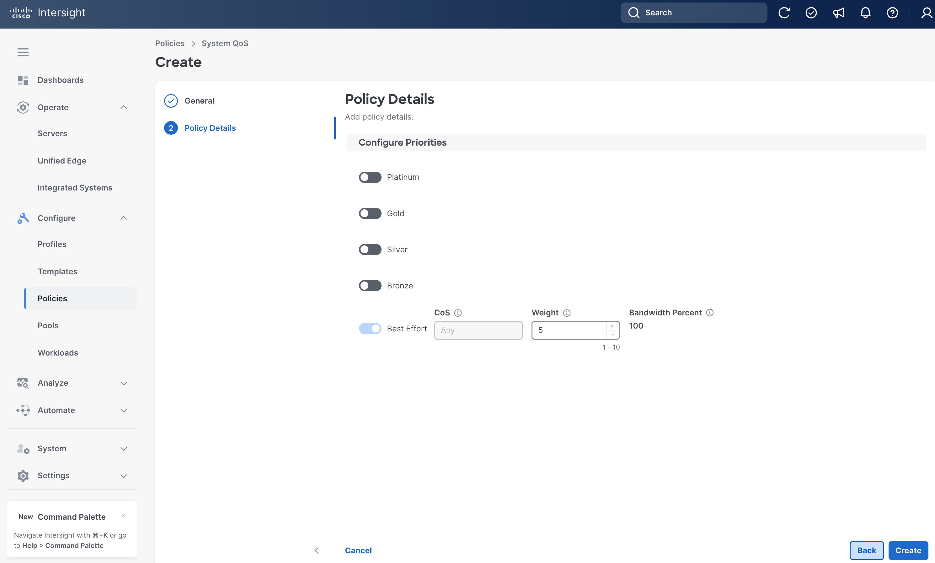
Procedure 10. Configure System QoS Policy
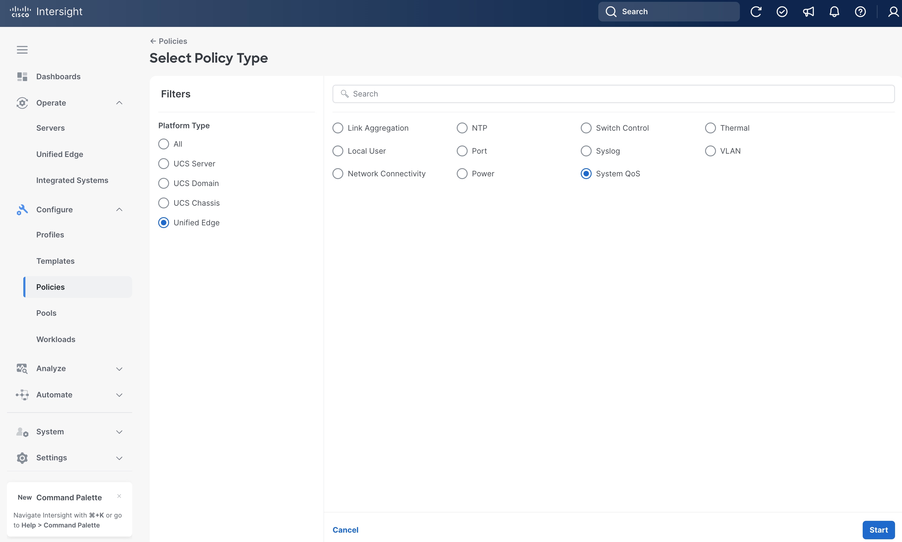
Step 1. Go to Configure > Policies. Click Create Policy.
Step 2. Click Unified Edge in the Filters section, then select System QoS.
Step 3. Click Start.
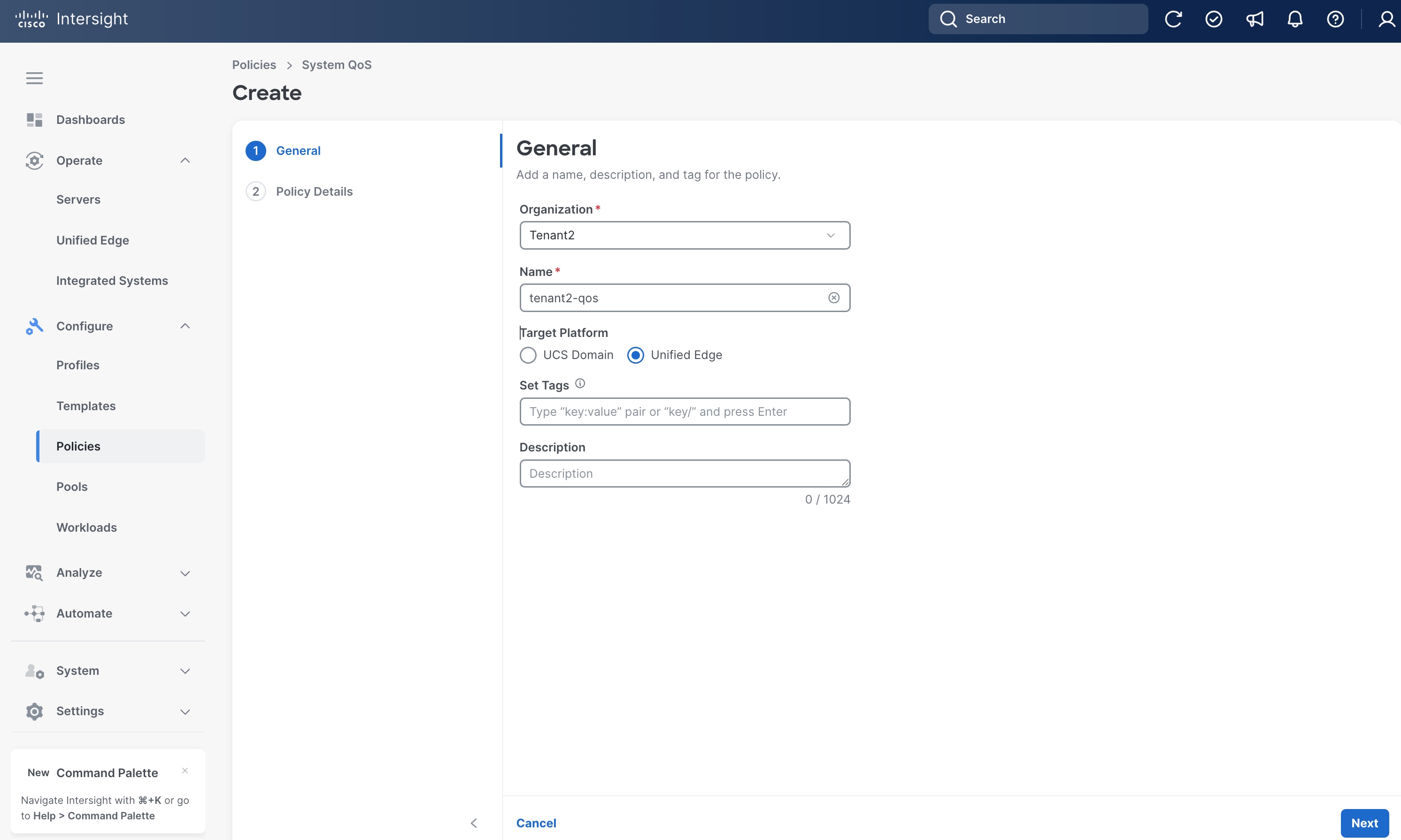
Step 4. On the General page, select the correct Organization, for example, Tenant2.
Step 5. Provide a Name for the policy, for example, tenant2-qos.
Step 6. Select Unified Edge as the Target Platform.
Step 7. (Optional) Provide Tags and Description.
Step 8. Click Next.
Step 9. On the Policy Details page, leave everything at the default settings.
Step 10. Click Create.
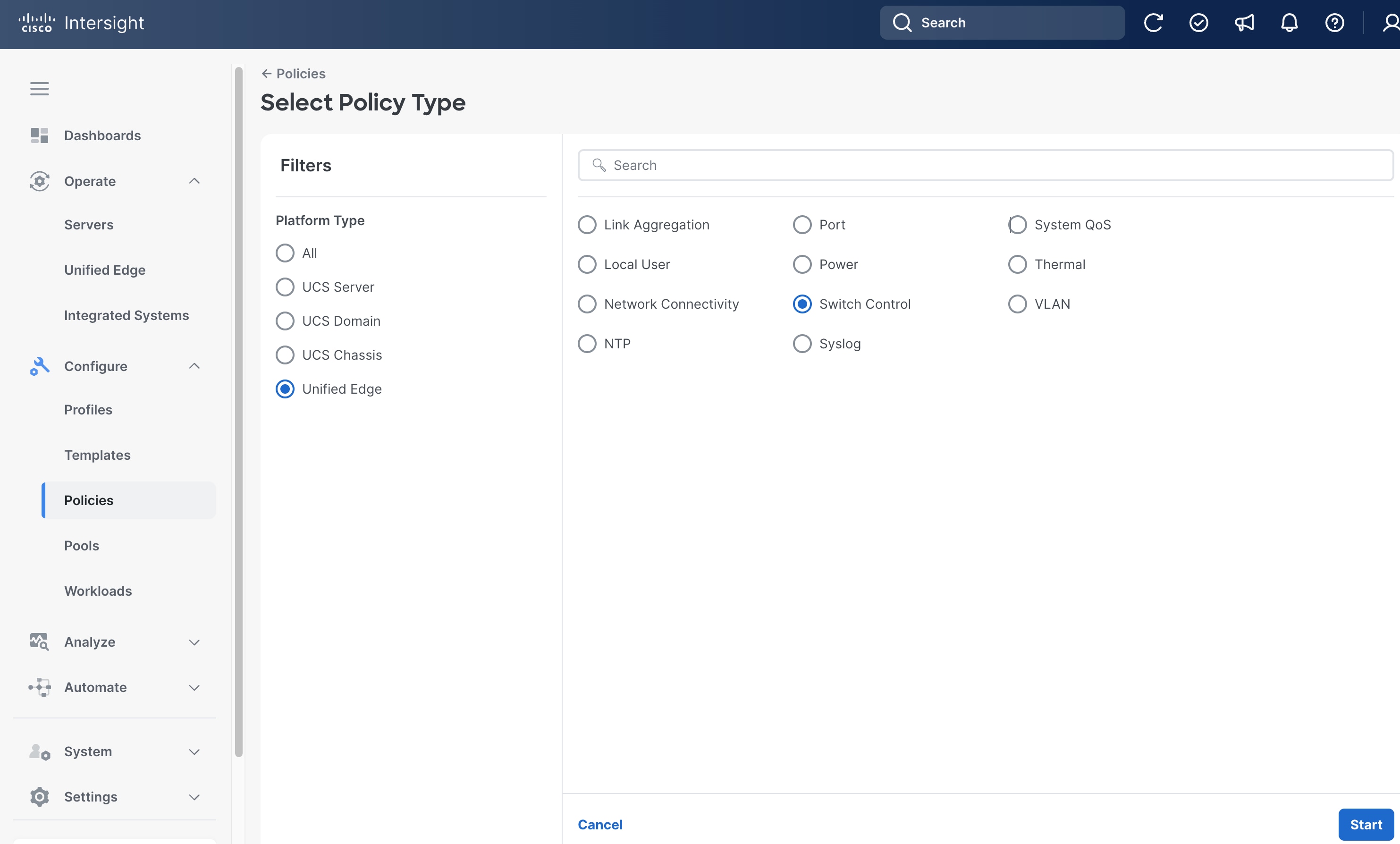
Procedure 11. Configure Switch Control Policy
Step 1. Go to Configure > Policies. Click Create Policy.
Step 2. Click Unified Edge in the Filters section, then select Switch Control.
Step 3. Click Start.
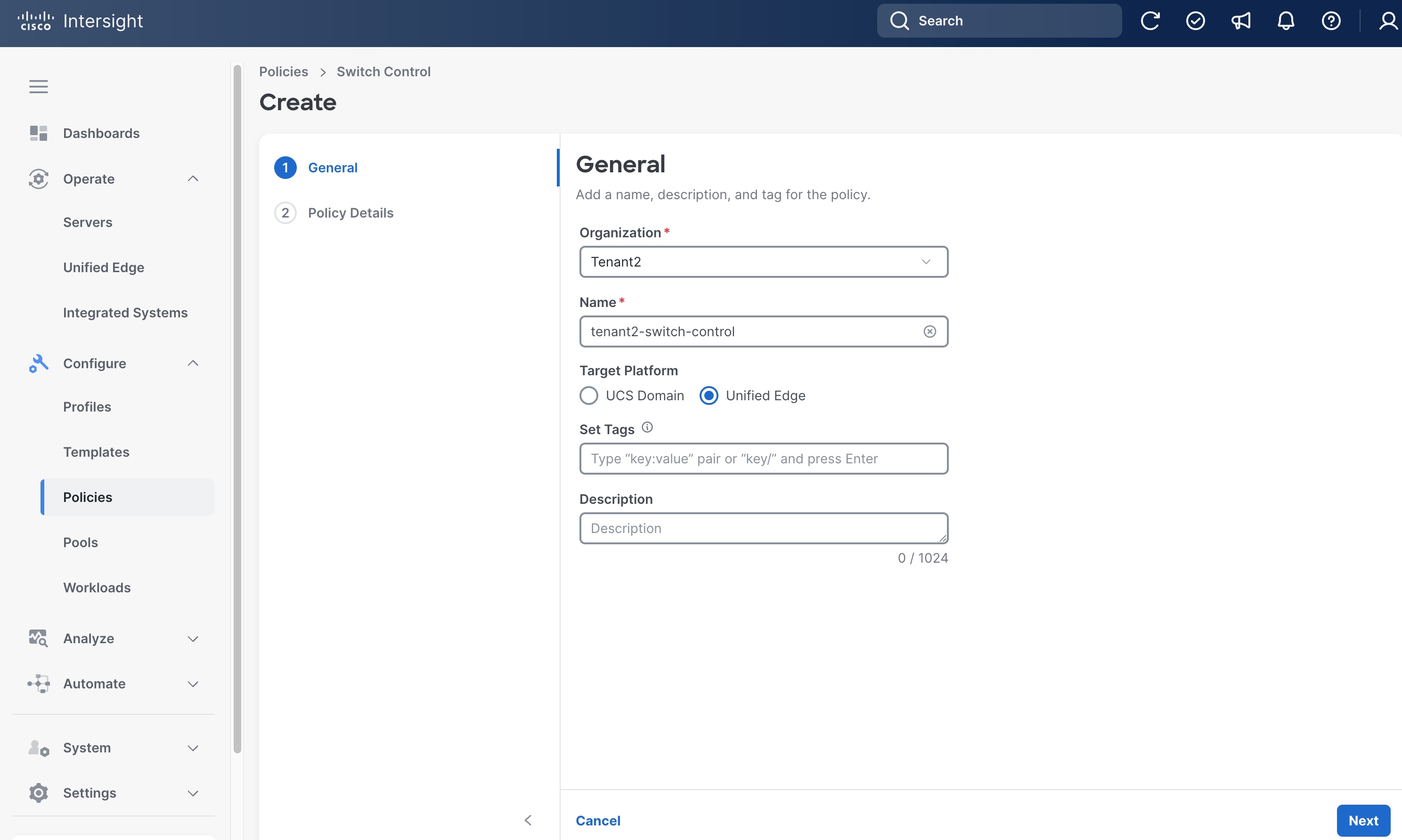
Step 4. On the General page, select the correct Organization, for example, Tenant2.
Step 5. Provide a Name for the policy, for example, tenant2-switch-control.
Step 6. Select Unified Edge as the Target Platform.
Step 7. (Optional) Provide Tags and Description.
Step 8. Click Next.
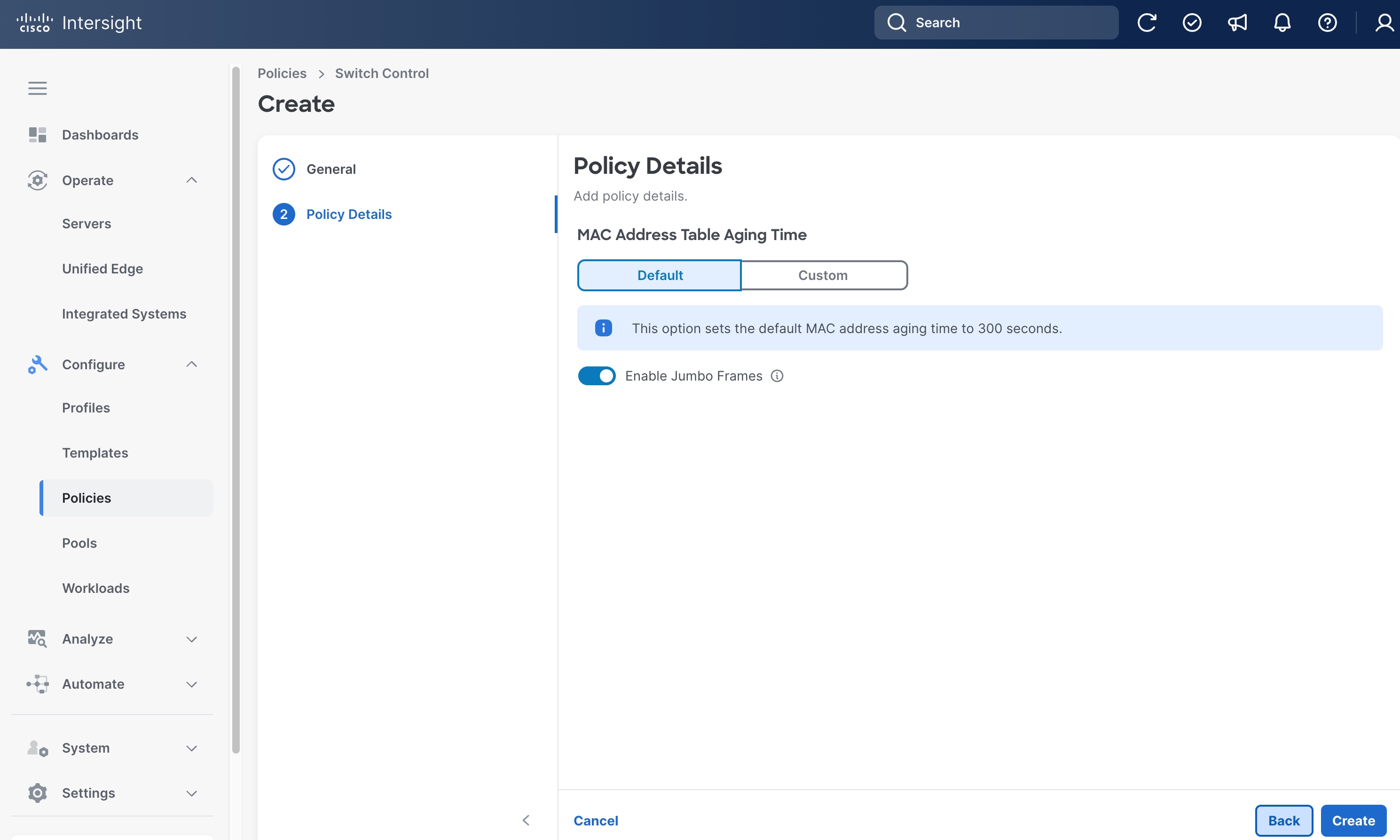
Step 9. On the Policy Details page, make sure Enable Jumbo Frames is switched on.
Step 10. Leave other fields at their default settings.
Step 11. Click Create.
Procedure 12. Configure NTP Policy
Step 1. Go to Configure > Policies. Click Create Policy.
Step 2. Click Unified Edge in the Filters section, then select NTP.
Step 3. Click Start.
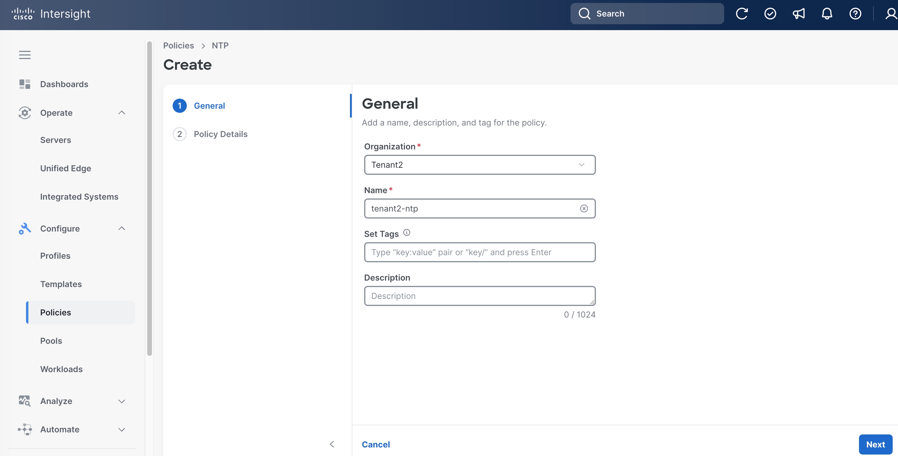
Step 4. On the General page, select the correct Organization, for example, Tenant2.
Step 5. Provide a Name for the policy, for example, tenant2-ntp.
Step 6. (Optional) Provide Tags and Description.
Step 7. Click Next.
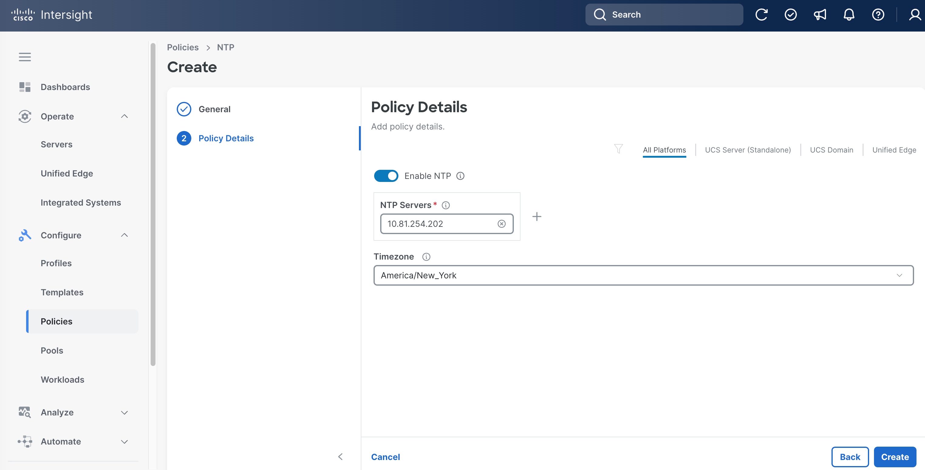
Step 8. On the Policy Details page, add one or more NTP Servers, for example, 10.81.254.202.
Step 9. Set the Timezone, for example, America/New_York.
Step 10. Click Create.
Procedure 13. Configure Network Connectivity Policy
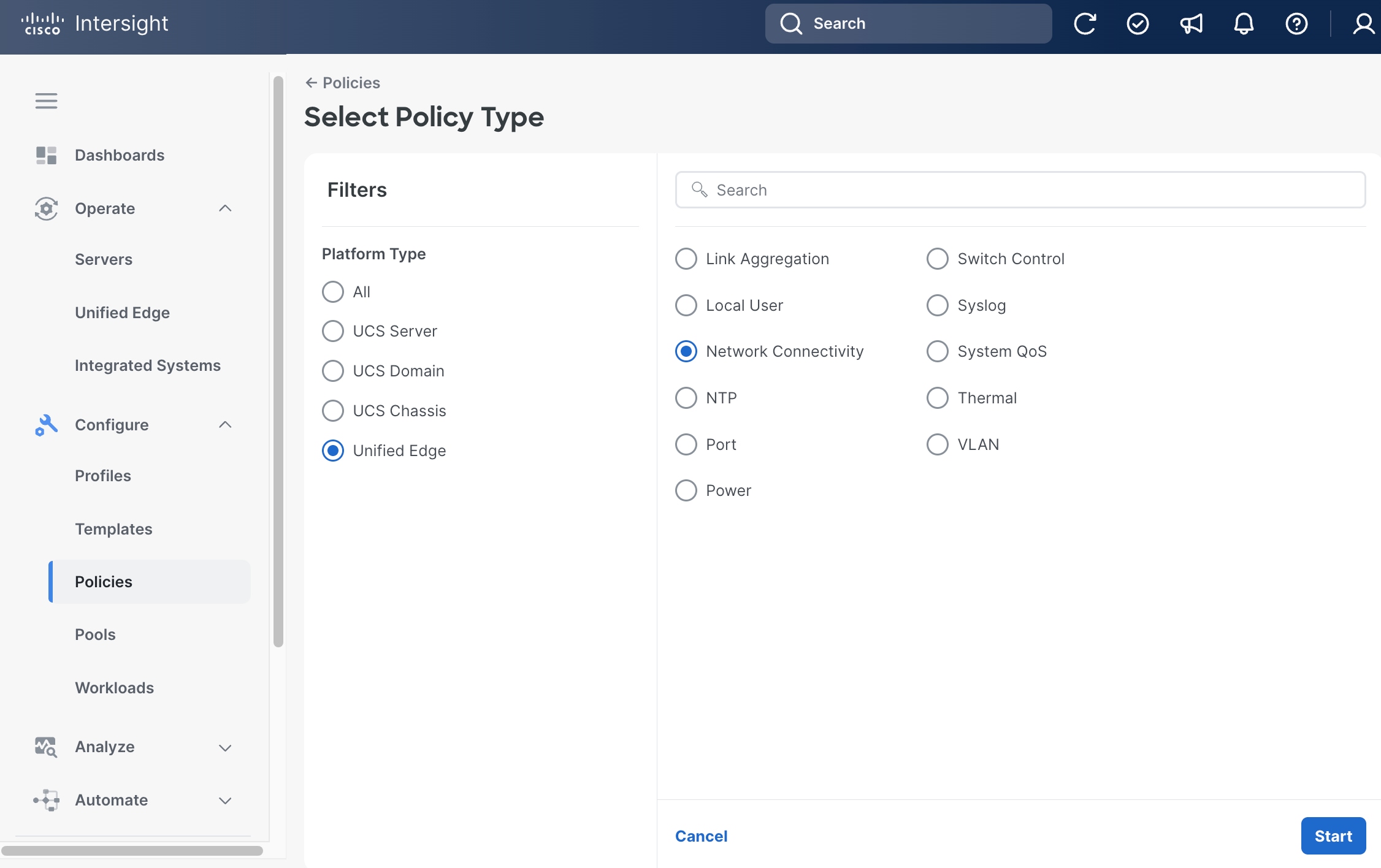
Step 1. Go to Configure > Policies. Click Create Policy.
Step 2. Click Unified Edge in the Filters section, then select Network Connectivity.
Step 3. Click Start.
Step 4. On the General page, select the correct Organization, for example, Tenant2.
Step 5. Provide a Name for the policy, for example, tenant2-network-conn-1.
Step 6. (Optional) Provide Tags and Description.
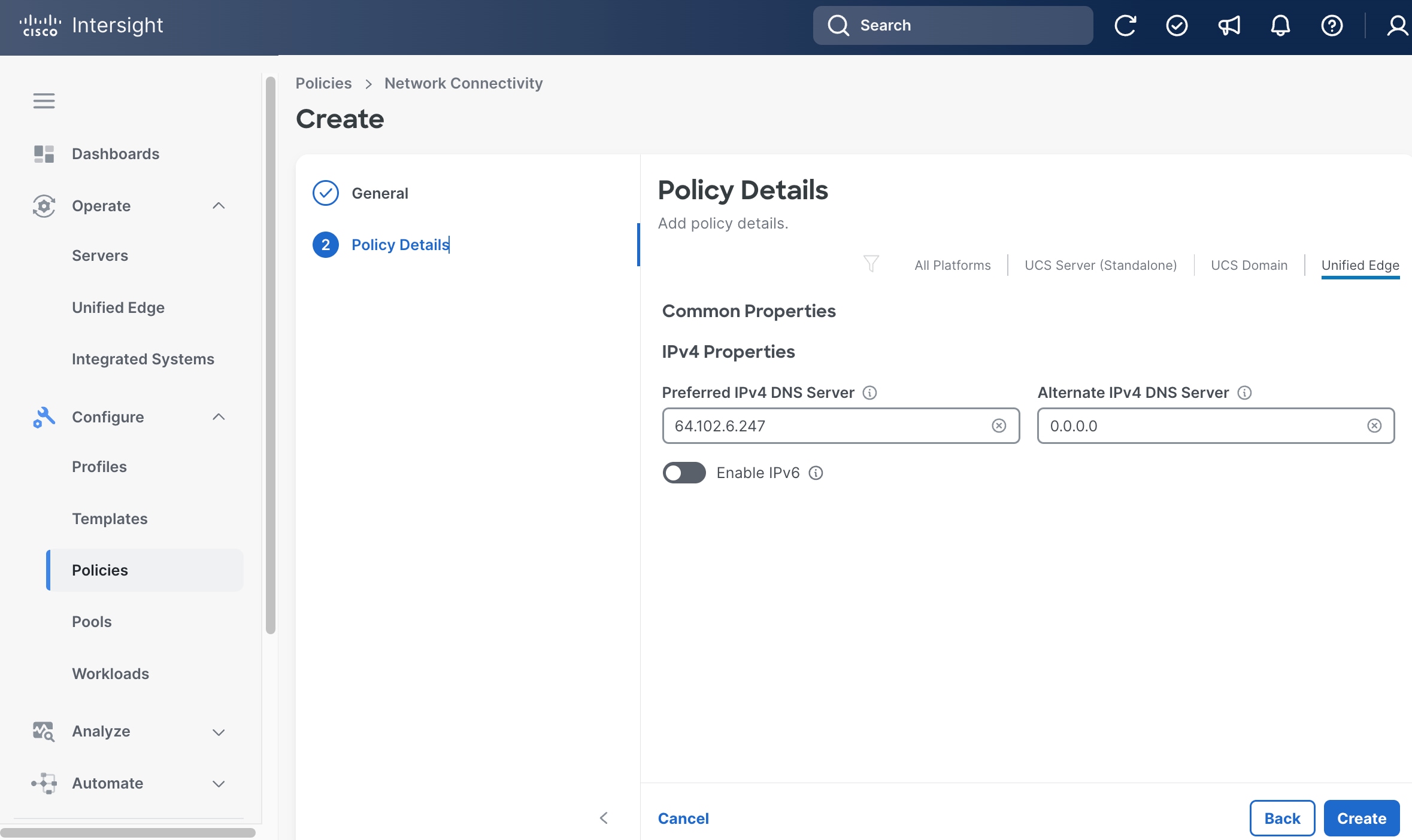
Step 7. Click Next.
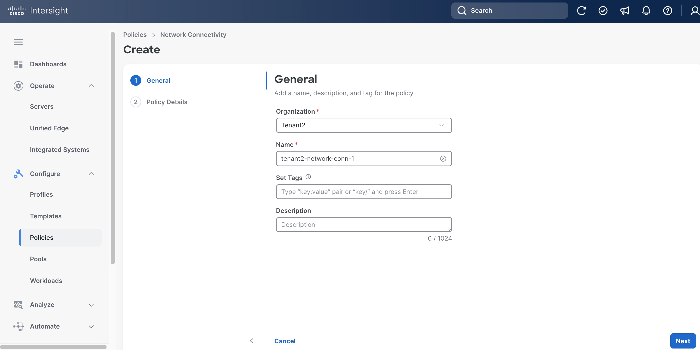
Step 8. On the Policy Details page, click Unified Edge.
Step 9. Provide at least one IPv4 DNS server IP address.
Step 10. Click Create.
Procedure 14. Configure Local User Policy
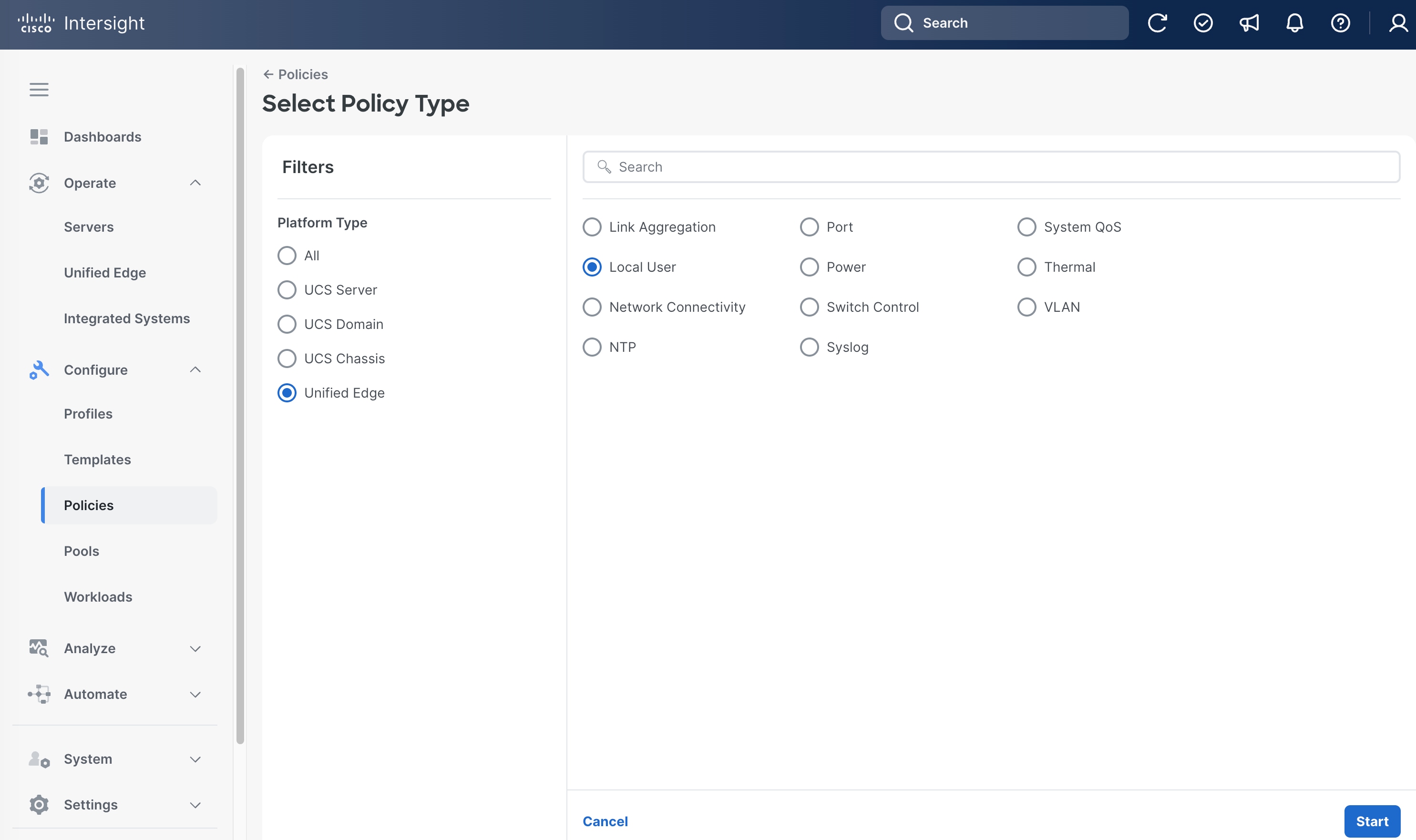
Step 1. Go to Configure > Policies. Click Create Policy.
Step 2. Click Unified Edge in the Filters section, then select Local User.
Step 3. Click Start.
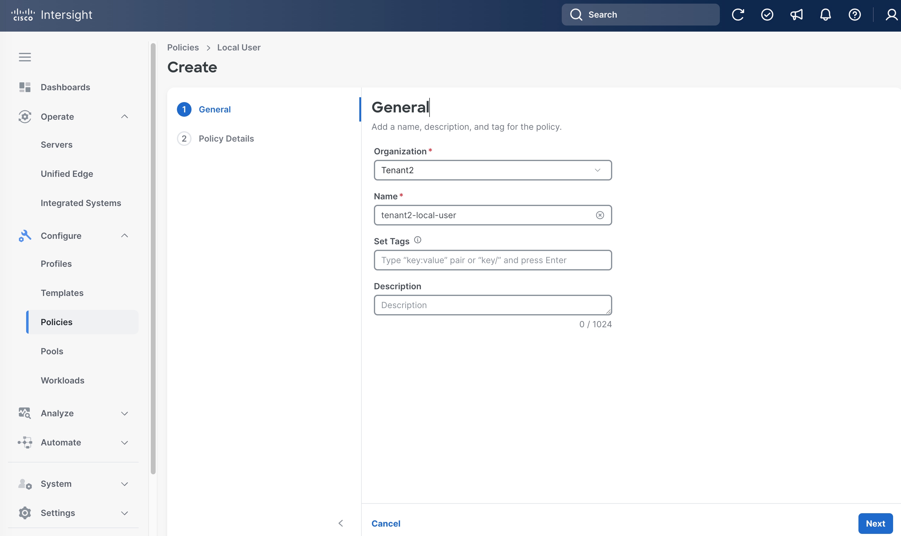
Step 4. On the General page, select the correct Organization, for example, Tenant2.
Step 5. Provide a Name for the policy, for example, tenant2-local-user.
Step 6. (Optional) Provide Tags and Description.
Step 7. Click Next.
Step 8. On the Policy Details page, click Add New User.
Step 9. Leave Username as admin.
Step 10. Select Role as admin and set Password.
Step 11. Click Create.
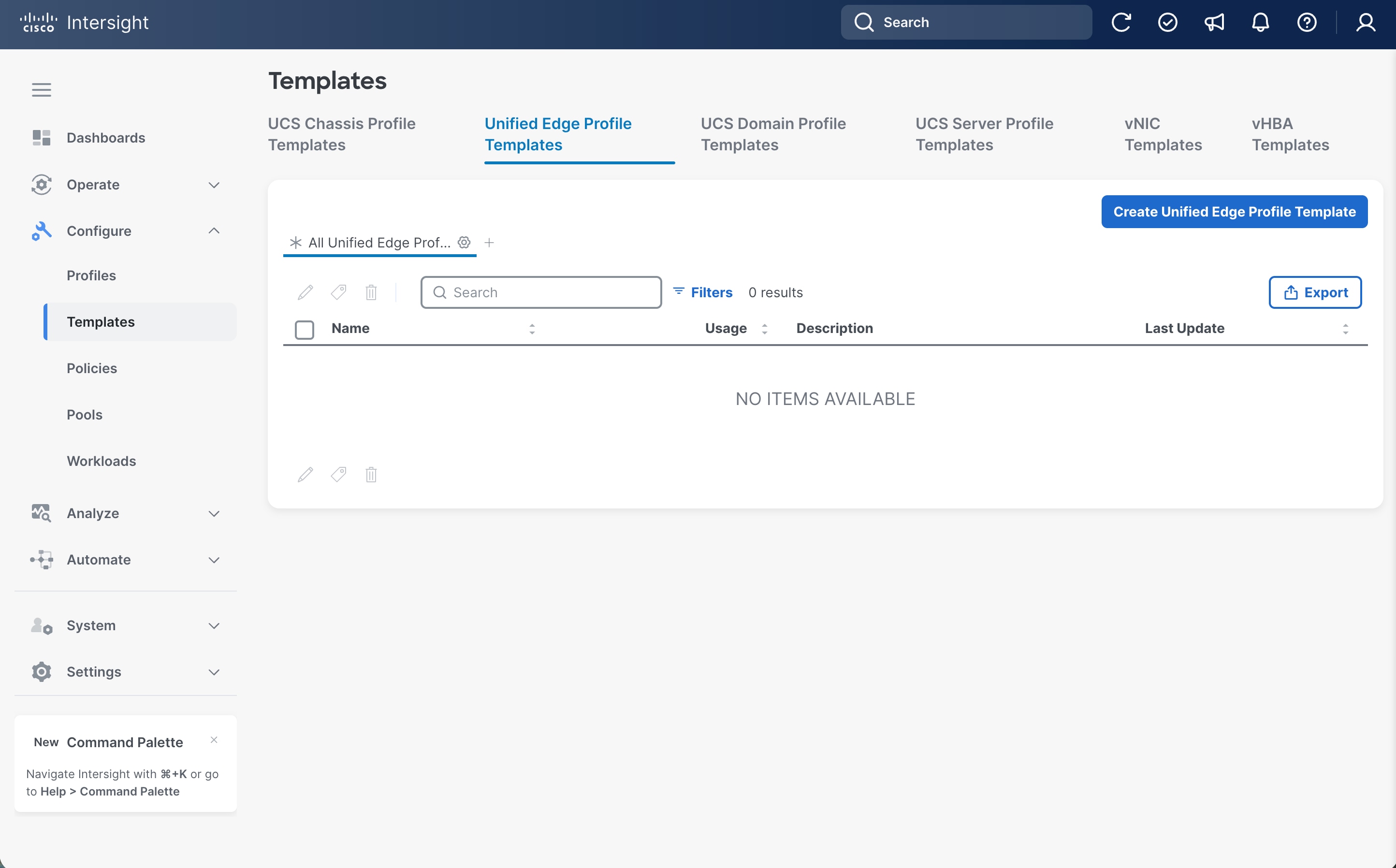
Procedure 15. Configure Cisco Unified Edge Profile Templates
Step 1. Go to Configure > Templates. Select Unified Edge Profile Templates at the top and click Create Unified Edge Profile Template.
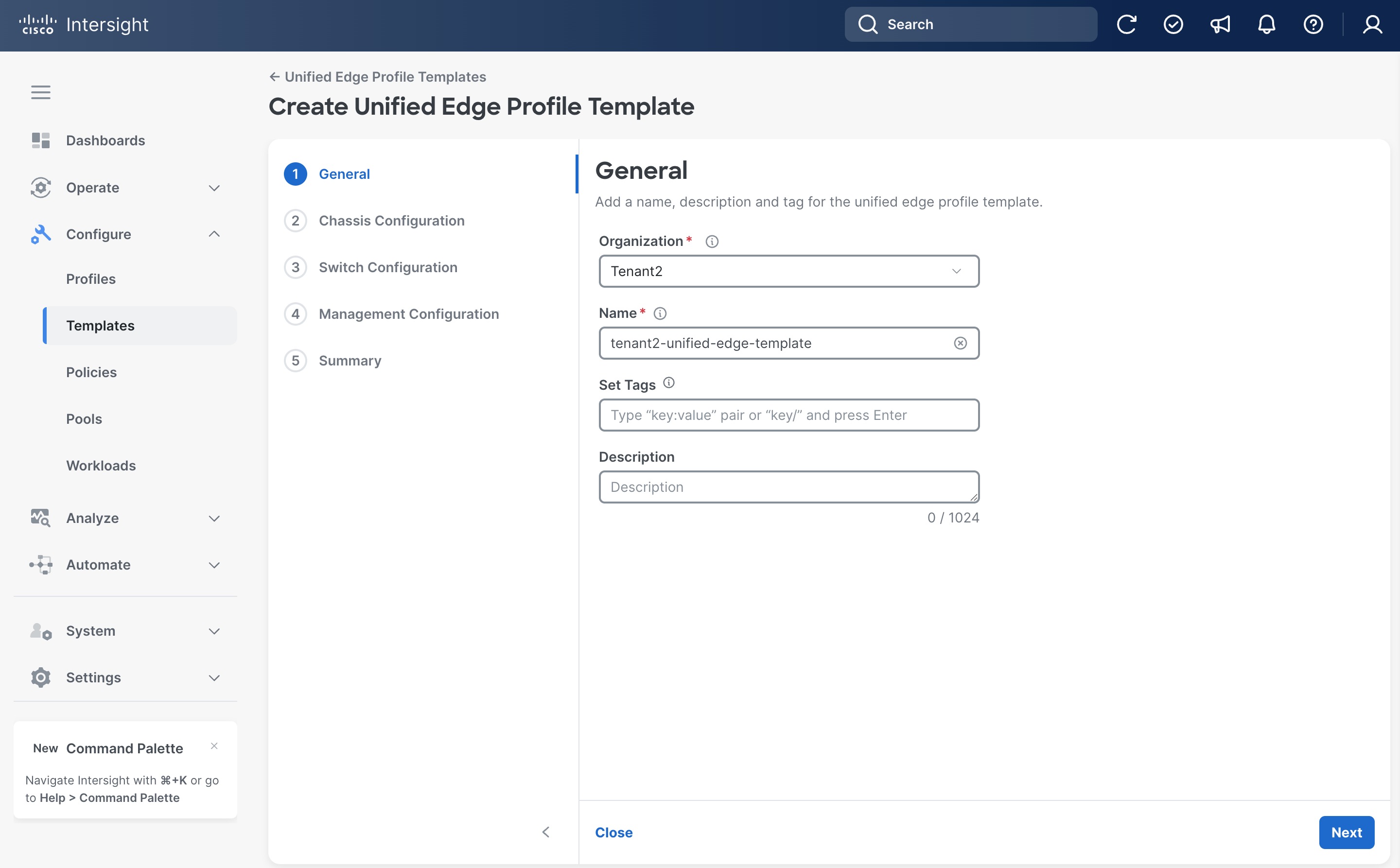
Step 2. Select the correct Organization, for example, Tenant2.
Step 3. Provide a Name for the template, for example, tenant2-unified-edge-template.
Step 4. (Optional) Provide Tags and Description.
Step 5. Click Next.
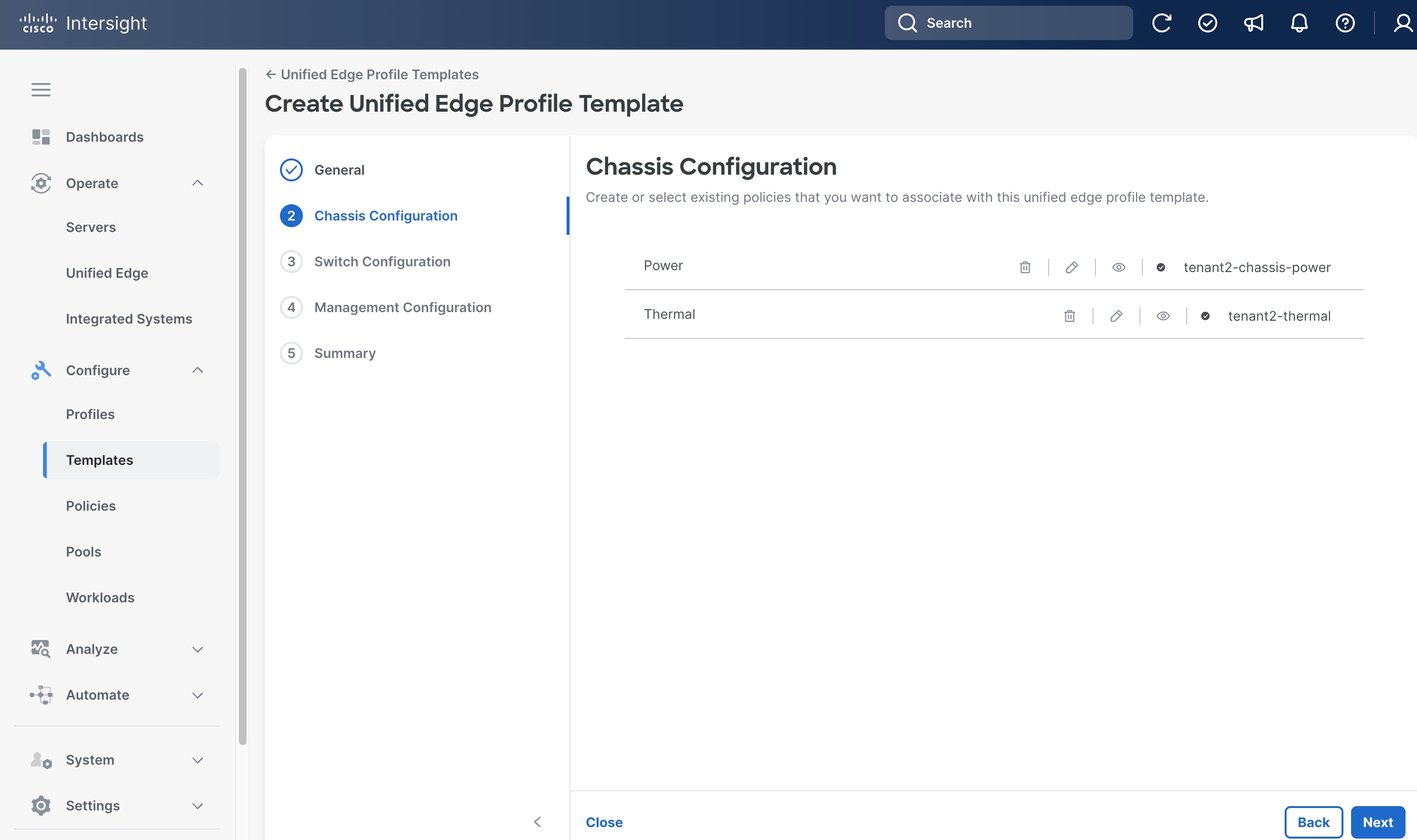
Step 6. On the Chassis Configuration page, click Select Policy next to Power.
Step 7. Select the Power Policy created in the previous step, which is tenant2-chassis-power.
Step 8. Click Select.
Step 9. From the Chassis Configuration page, click Select Policy next to Thermal.
Step 10. Click Select.
Step 11. From the Chassis Configuration page, click Next
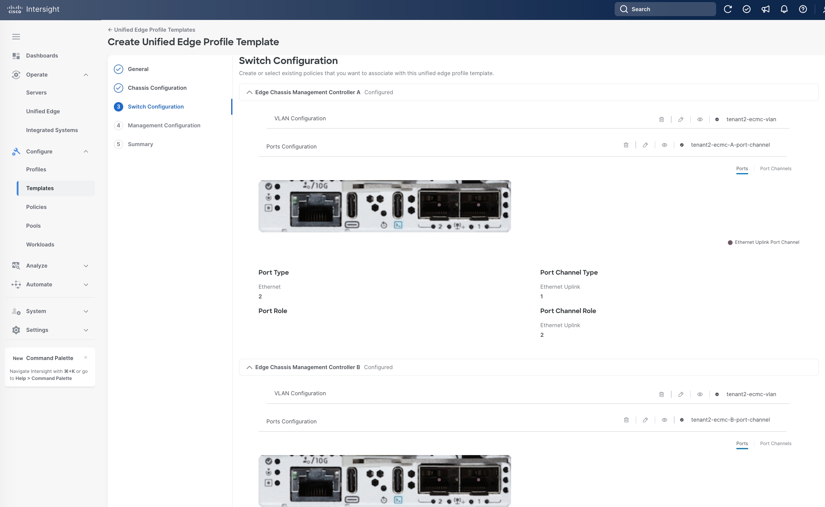
Step 12. On the Switch Configuration page, in the Edge Chassis Management Controller A section, click Select Policy next to VLAN Configuration.
Step 13. Select the VLAN Policy created in the previous step, which is tenant2-ecmc-vlan.
Step 14. Click Select.
Step 15. From the Switch Configuration page, in the Edge Chassis Management Controller A section, click Select Policy next to Ports Configuration.
Step 16. Select the Port Policy for eCMC-A created in the previous step, which is tenant2-ecmc-A-port-channel.
Step 17. Click Select.
Step 18. From the Switch Configuration page, in the Edge Chassis Management Controller B section, click Select Policy next to VLAN Configuration.
Step 19. Select the VLAN Policy created in the previous step, which is tenant2-ecmc-vlan.
Step 20. Click Select.
Step 21. From the Switch Configuration page, in the Edge Chassis Management Controller B section, click Select Policy next to Ports Configuration.
Step 22. Select the Port Policy for eCMC-B created in the previous step, which is tenant2-ecmc-B-port-channel.
Step 23. Click Select.
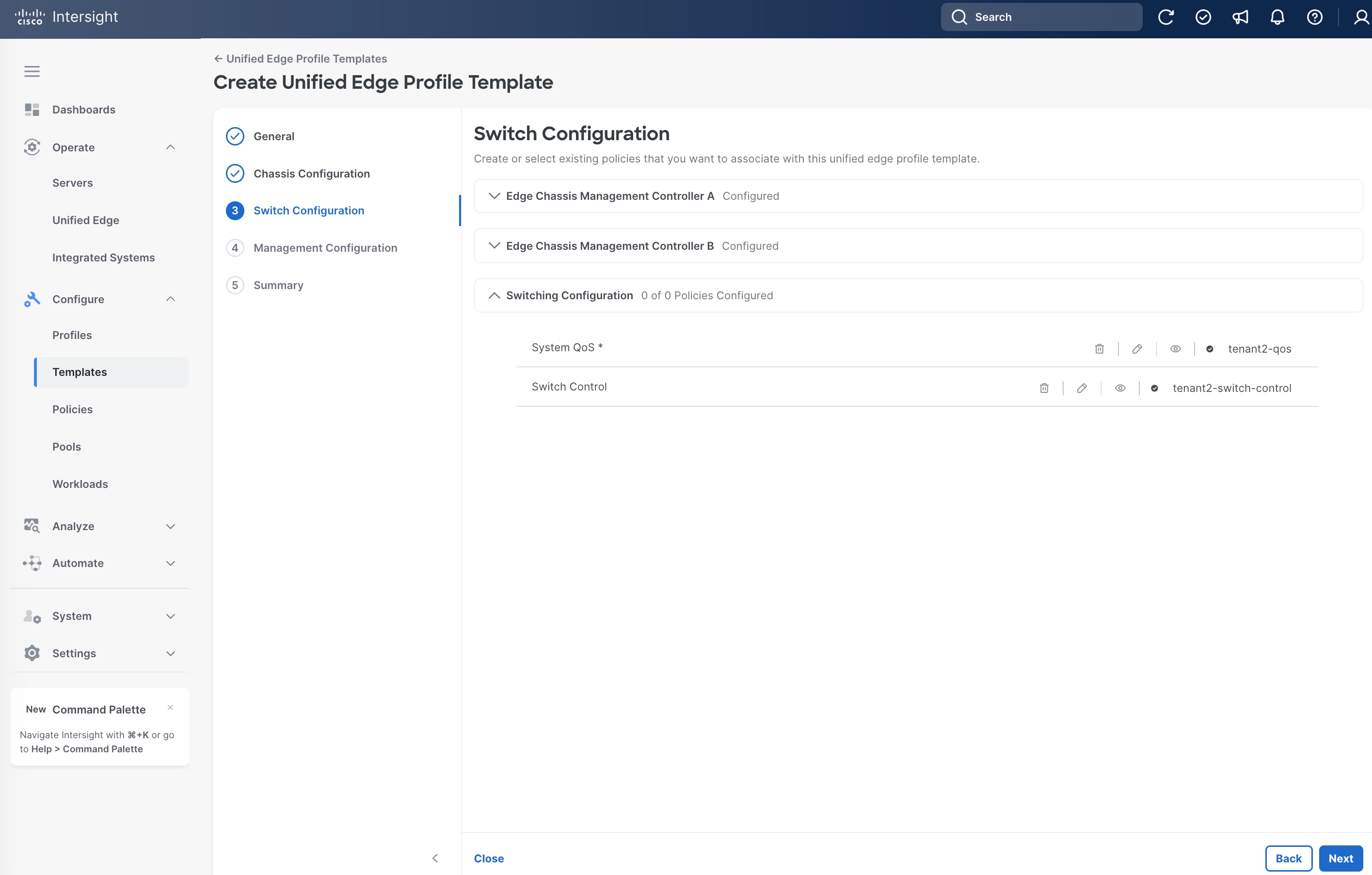
Step 24. From the Switch Configuration page, in the Switching Configuration section, click Select Policy next to System QoS.
Step 25. Select the QoS Policy created in the previous step, which is tenant2-qos.
Step 26. Click Select.
Step 27. From the Switch Configuration page, in the Switching Configuration section, click Select Policy next to Switch Control.
Step 28. Select the Switch Control Policy created in the previous step, which is tenant2-switch-control.
Step 29. Click Select.
Step 30. From the Switch Configuration page, click Next.
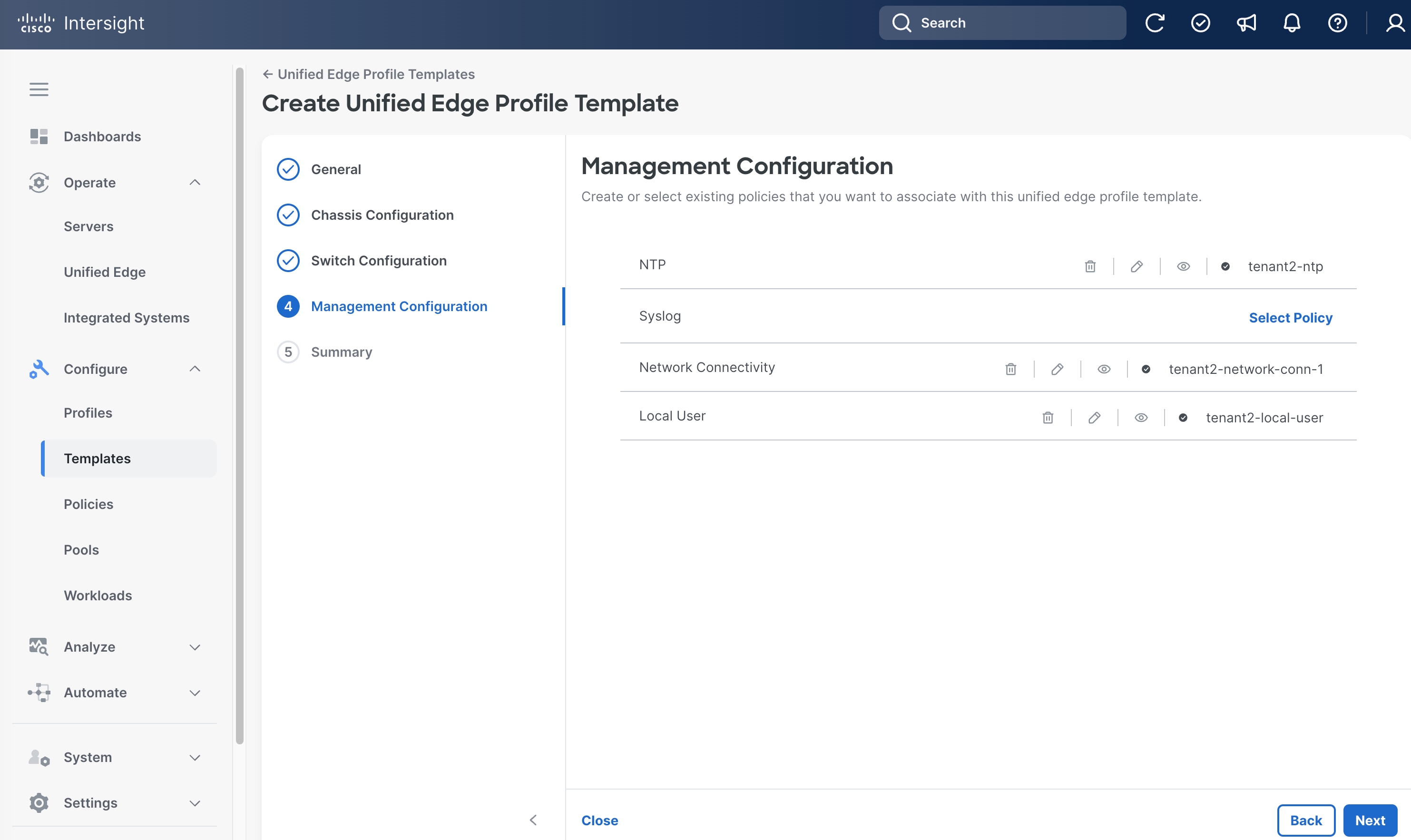
Step 31. On the Management Configuration page, click Select Policy next to NTP.
Step 32. Select the NTP Policy created in the previous step, which is tenant2-ntp.
Step 33. Click Select.
Step 34. From the Management Configuration page, click Select Policy next to Network Connectivity.
Step 35. Select the Network Connectivity Policy created in the previous step, which is tenant2-network-conn-1.
Step 36. Click Select.
Step 37. From the Management Configuration page, click Select Policy next to Local User.
Step 38. Select the Local User Policy created in the previous step, which is tenant2-local-user.
Step 39. Click Select.
Step 40. From the Management Configuration page, click Next.
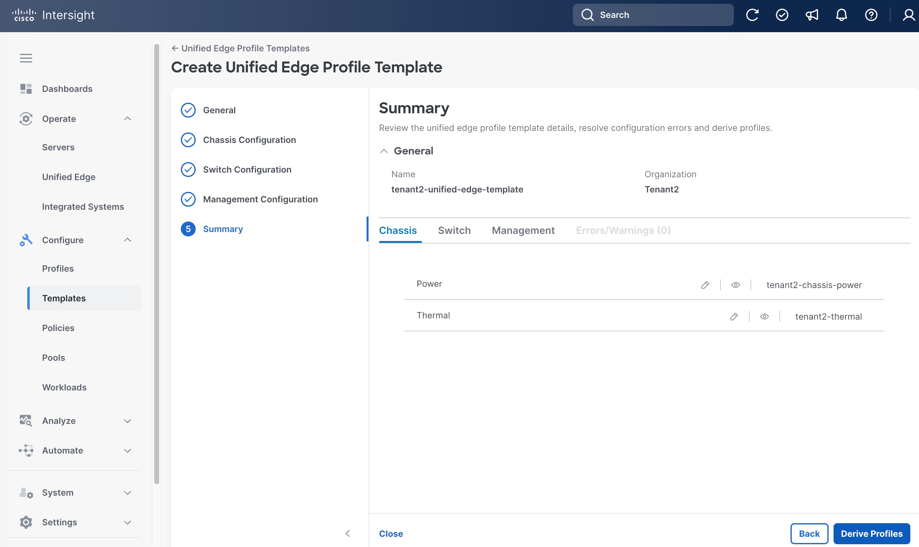
Step 41. On the Summary page, click Derive Profiles.
Apply Unified Edge Configuration
Procedure 1. Derive and Assign Cisco Unified Edge Profile
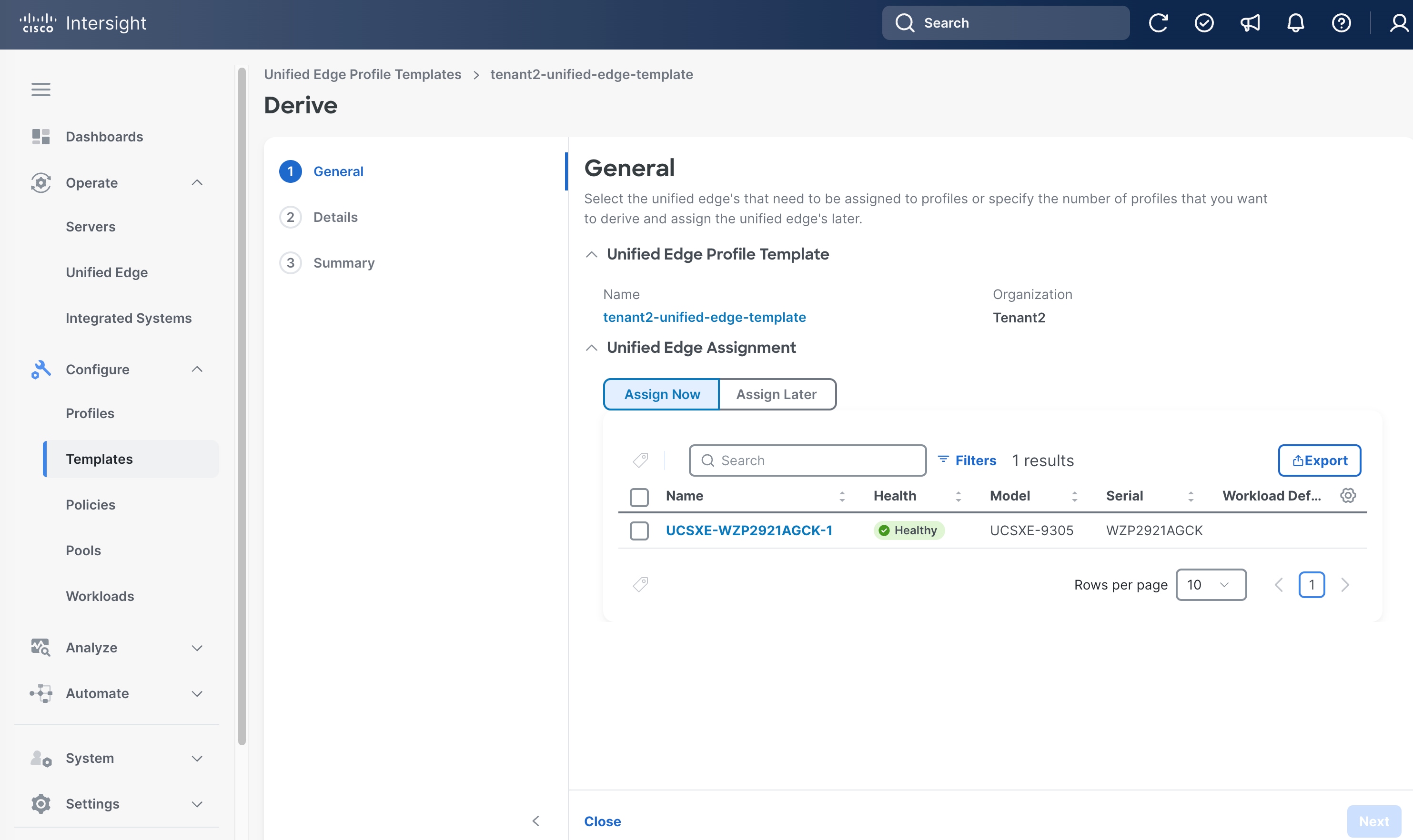
Step 1. On the General page, select the newly claimed Unified Edge Chassis in the Unified Edge Assignment section.
Step 2. Click Next.
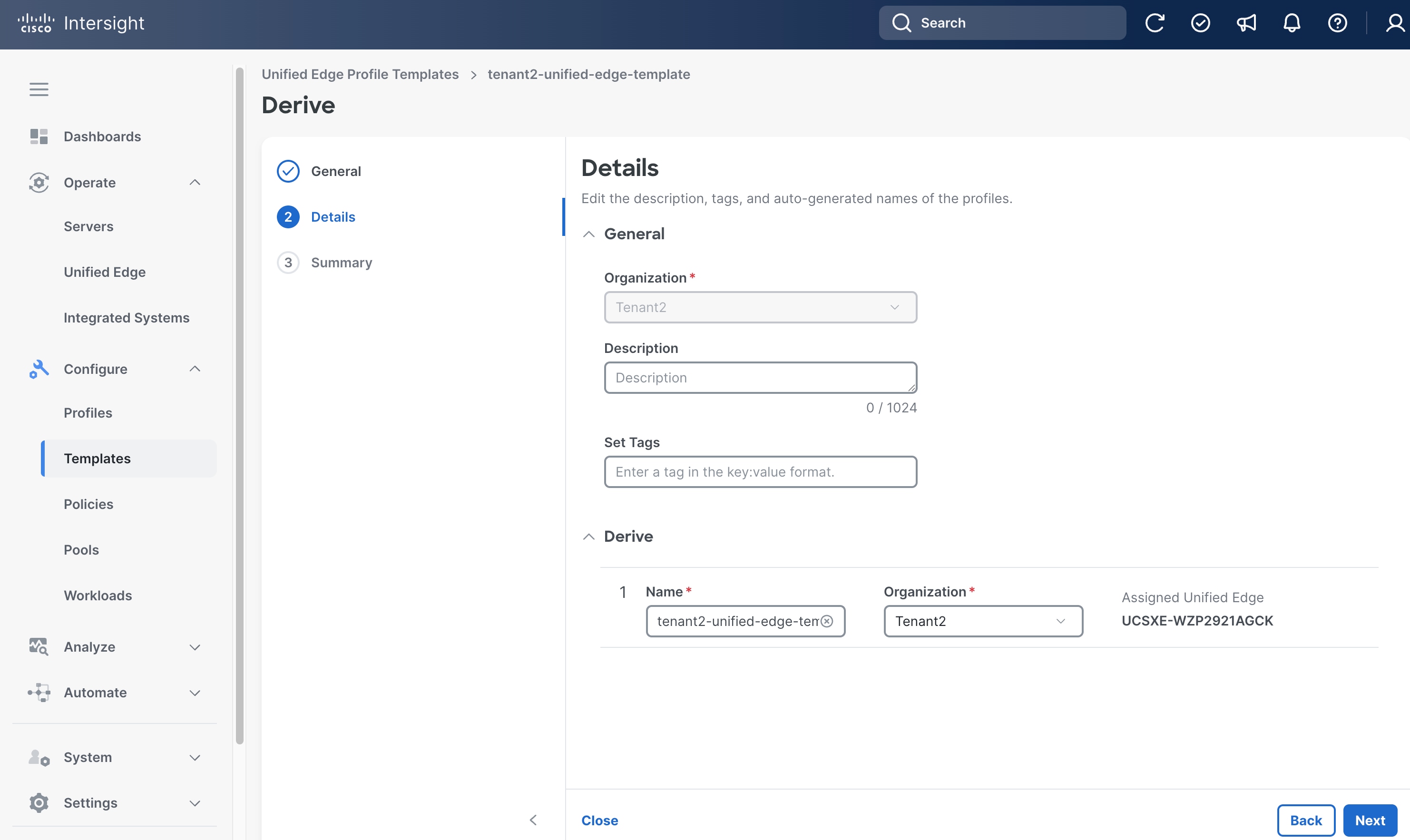
Step 3. On the Details page, select the correct Organization, for example, Tenant2.
Step 4. (Optional) Provide Description and Tags.
Step 5. Leave other field at its default setting.
Step 6. Click Next.
Step 7. On the Summary page, click Derive.
Step 8. Go to Configure > Profiles.
Step 9. Click Unified Edge Profiles.
Step 10. Select the newly created Unified Edge Profile.
Step 11. Click the ellipsis (…) at the end of the row. In the drop-down list, click Deploy.
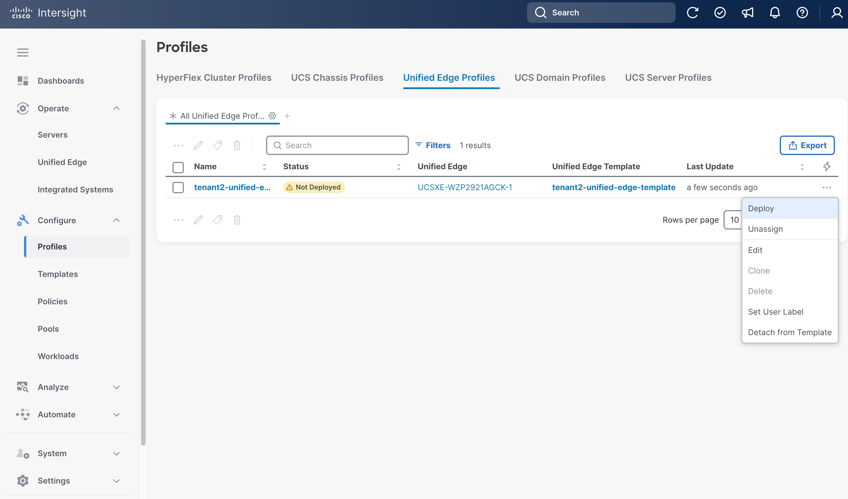
Step 12. Click Deploy in the pop-up window.
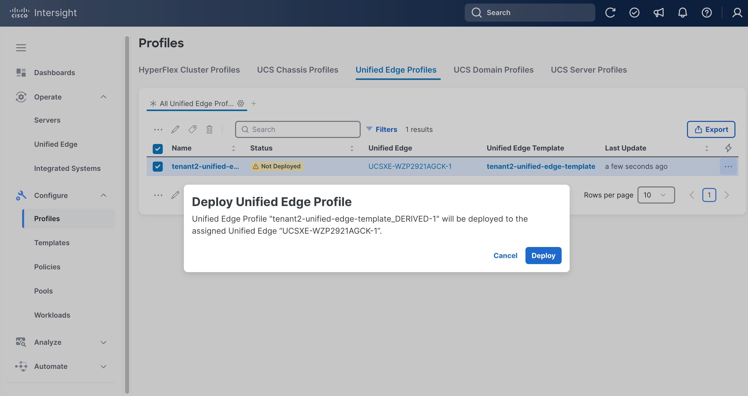
Step 13. The deployment will take a while to complete. Click the checkmark icon at the upper-right corner to check the status of the profile deployment request.
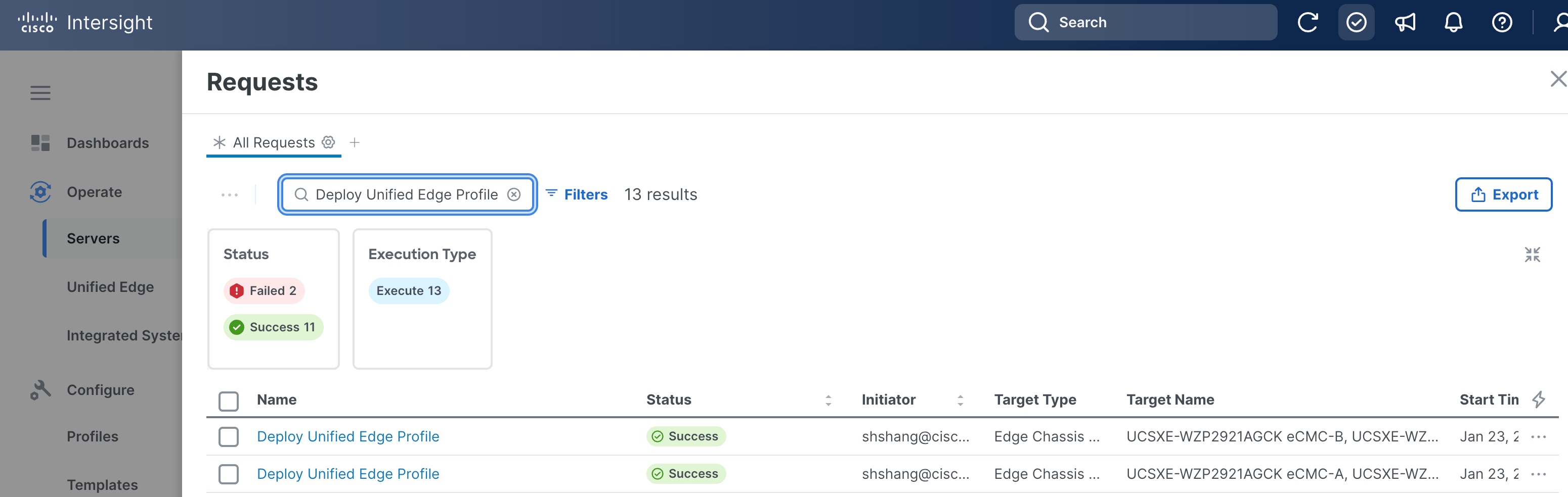
Step 14. Go to Configure > Profiles. Verify that the unified edge profile has been successfully deployed. The Status should be OK.

Step 15. Go to Operate > Unified Edge. Verify that the Health status of the newly added UCS XE9305 is Healthy.
Step 16. Go to Operate > Servers and verify that all UCSXE-130C-M8 servers on UCS XE9305 chassis have been successfully discovered.
Create Server Profile Template
A server profile template enables resource management by simplifying policy alignment and server configuration. A server profile template is created using the server profile template wizard. Server Profiles are derived from Server Profile Templates and applied on Cisco UCSXE-130C-M8 servers that are discovered in Cisco Intersight.
Table 3 lists a summary view of the policies used in the validated design.
| Type |
Name |
Notes |
| Computer Configuration |
||
| BIOS |
tenant2-server-bios |
Sets BIOS configuration options for CPU, memory, virtualization, and platform features. |
| Boot Order |
tenant2-boot-order |
Specifies the boot device sequence and boot mode. |
| Power |
tenant2-server-power |
Control server power consumption and recovery after power events. |
| Virtual Media |
tenant2-vmedia-sno |
Enables mounting images to the server over the network. |
| Management Configuration |
||
| IMC Access |
tenant2-imc |
Defines the management IP address pool for KVM access. |
| Local User |
tenant2-local-user |
Used to enable KVM-based user access |
| Virtual KVM |
tenant2-vKVM |
Configures KVM and remote console access settings. |
| Storage Configuration |
||
| Storage |
tenant2-storage |
Defines storage configuration such as controller mode, RAID settings, and virtual drive parameters. |
| Network Configuration |
||
| LAN Connectivity |
tenant2-lan-conn-sno |
Defines vNIC configuration and network connectivity. Establishes how the server connects to embedded switches on eCMCs. |
| Ethernet QoS |
tenant2-qos |
Defines traffic priority, bandwidth limits, MTU, and Quality of Service parameters for vNIC Ethernet traffic. |
| Ethernet Network Group |
tenant2-eth-netgrp-sno |
Specifies VLAN assignments and network groupings that can be applied to vNICs. |
Table 4 lists the pools used in the validated design.
| Type |
Name |
Notes |
| UUID |
tenant2-uuid-pool |
Provides a range of UUID assigned to server profiles for server identification. |
| IP |
tenant2-inband-mgmt |
Range of IP addresses for server inband management. |
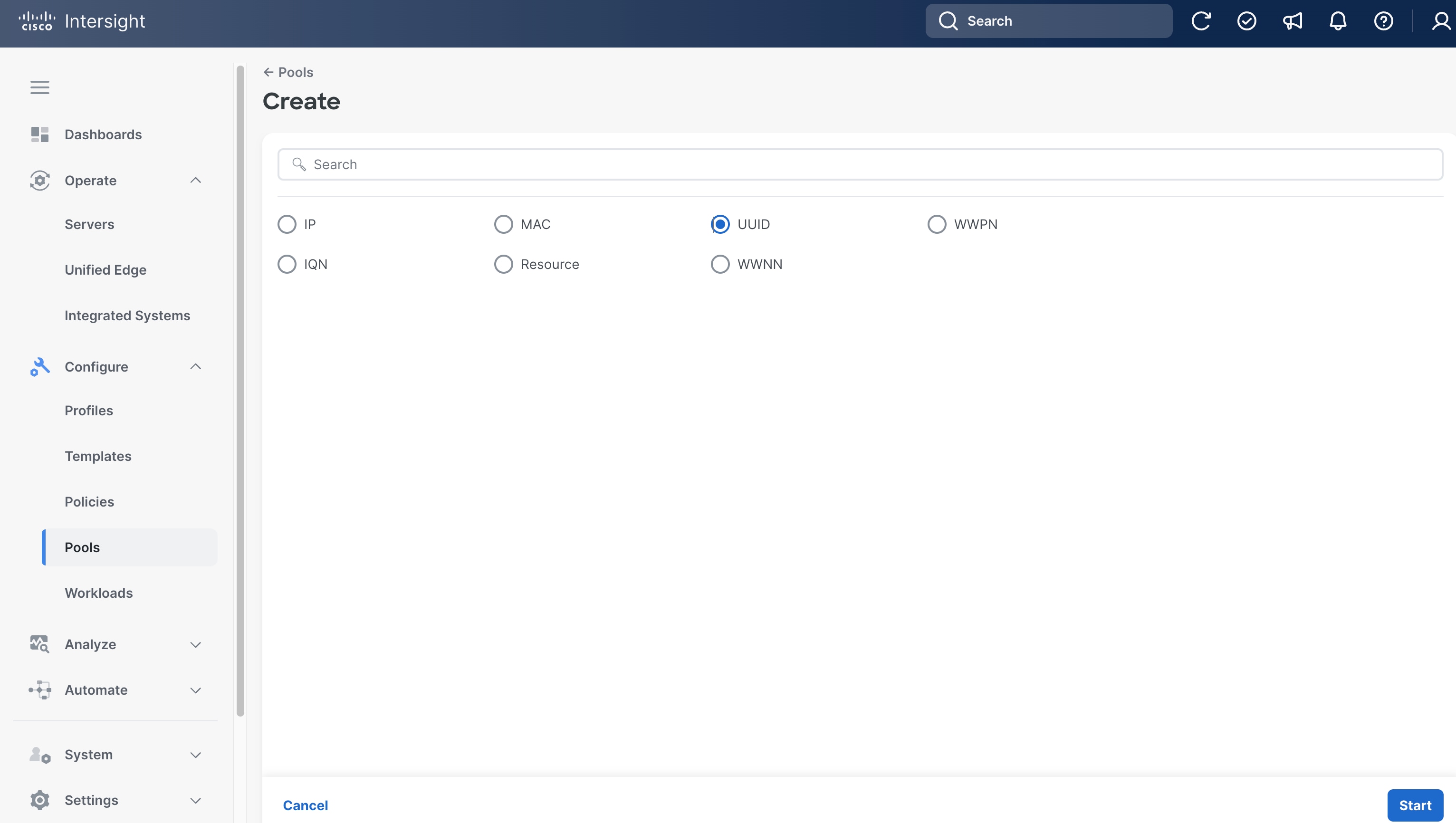
Procedure 1. Create UUID Pool
Step 1. Go to Configure > Pools.
Step 2. Click Pools and then click Create Pool.
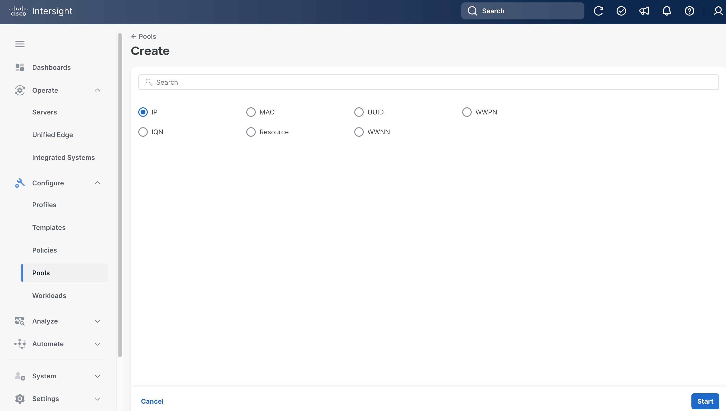
Step 3. On the Create page, select UUID.
Step 4. On General page, select the correct Organization, for example, Tenant2.
Step 5. Provide a Name for the pool, for example, tenant2-uuid-pool).
Step 6. (Optional) Provide Tags and Description.
Step 7. Click Next.

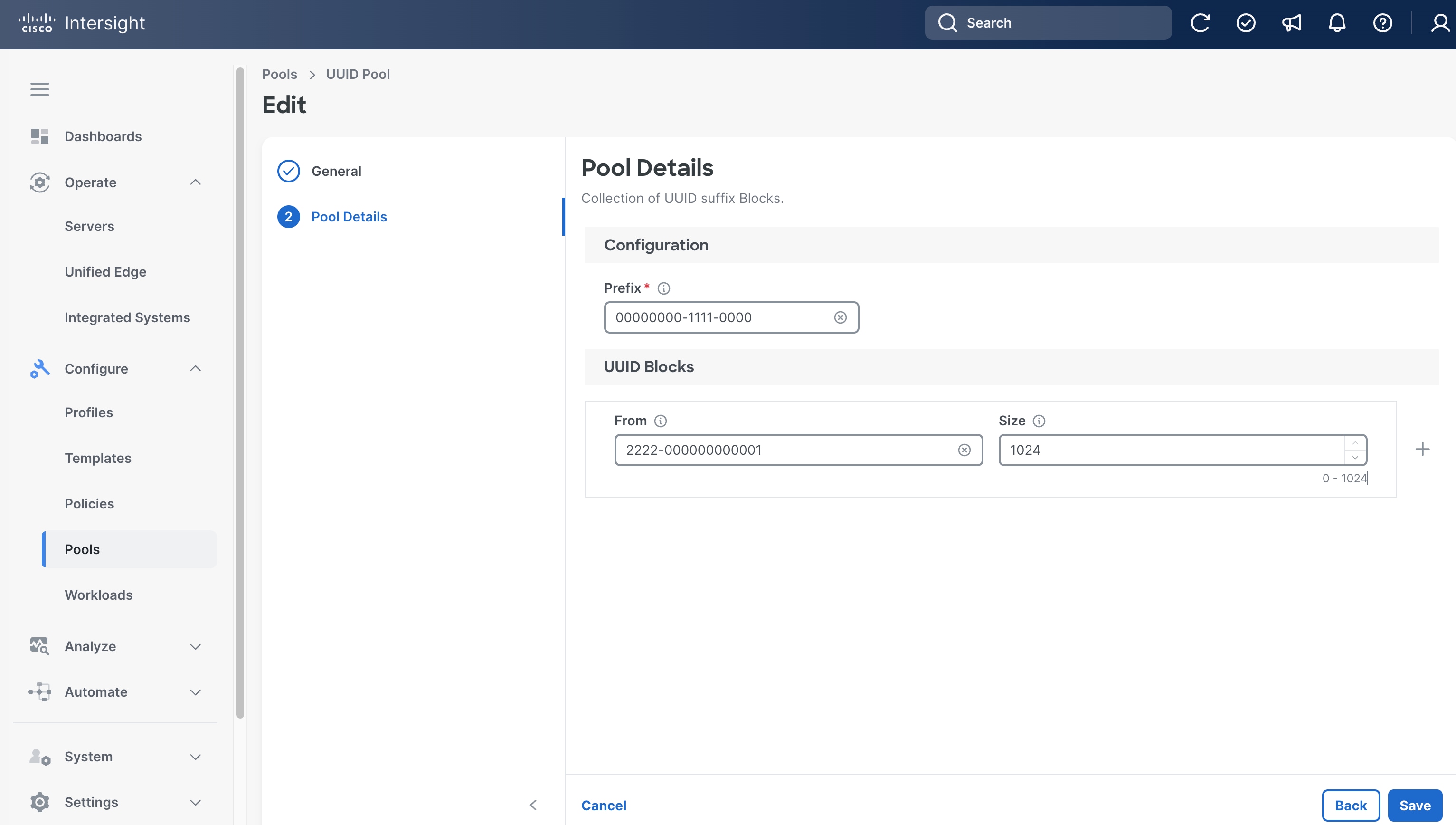
Step 8. On the Pool Details page, in Prefix section set the prefix. In this example, it is 00000000-1111-0000.
Step 9. In UUID Blocks section, set the range of UUID by specifying From and Size. In this example, they are 2222-000000000001 and 1024, respectively.
Step 10. Click Save.
Procedure 2. (Optional) Create Inband Management IP Pool
Step 1. Go to Configure > Pools, click the Pools tab and then click Create Pool.
Step 2. On the Create page, select IP.
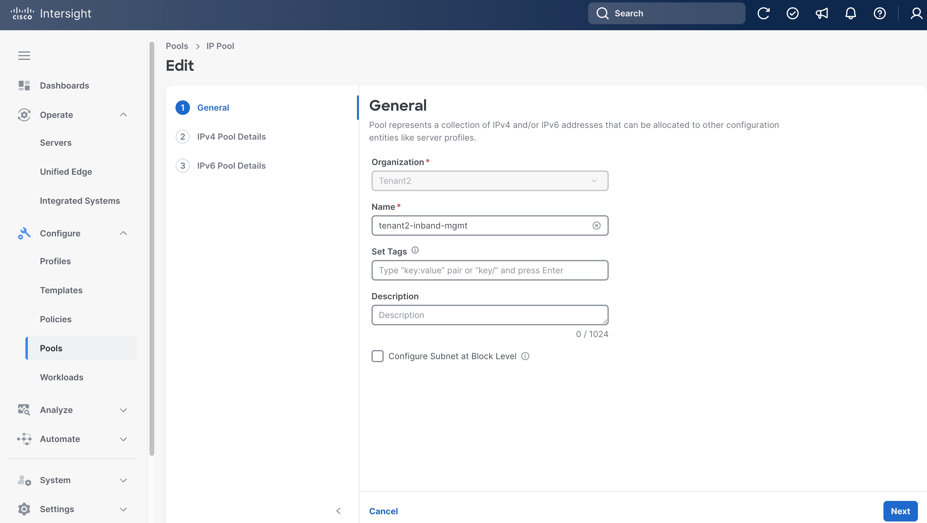
Step 3. On the General page, select the correct Organization, for example, Tenant2.
Step 4. Provide a Name for the pool, for example, tenant2-inband-mgmt.
Step 5. (Optional) Provide Tags and Description.
Step 6. Click Next.
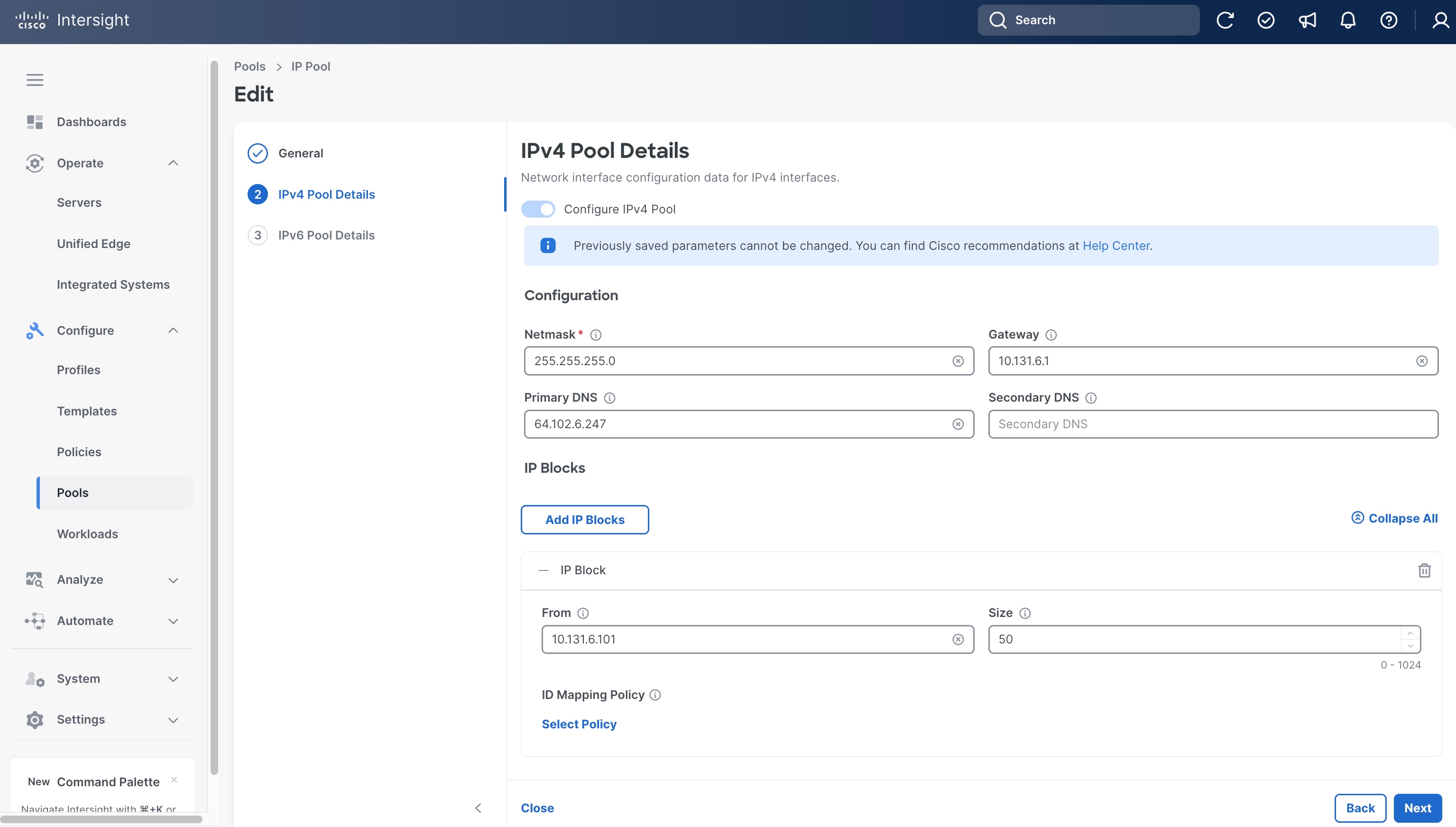
Step 7. On the IPv4 Pool Details page, in Configuration section, set Netmask, Gateway and Primary DNS. In this example, they are 255.255.255.0, 10.131.6.1 and 64.102.6.247, respectively.
Step 8. In IP Blocks section, set the range of IP by specifying From and Size. In this example, they are 10.131.6.101 and 50, respectively.
Step 9. Click Next.
Step 10. On the IPv6 Pool Details page, leave Configure IPv6 Pool switch off.
Step 11. Click Save.

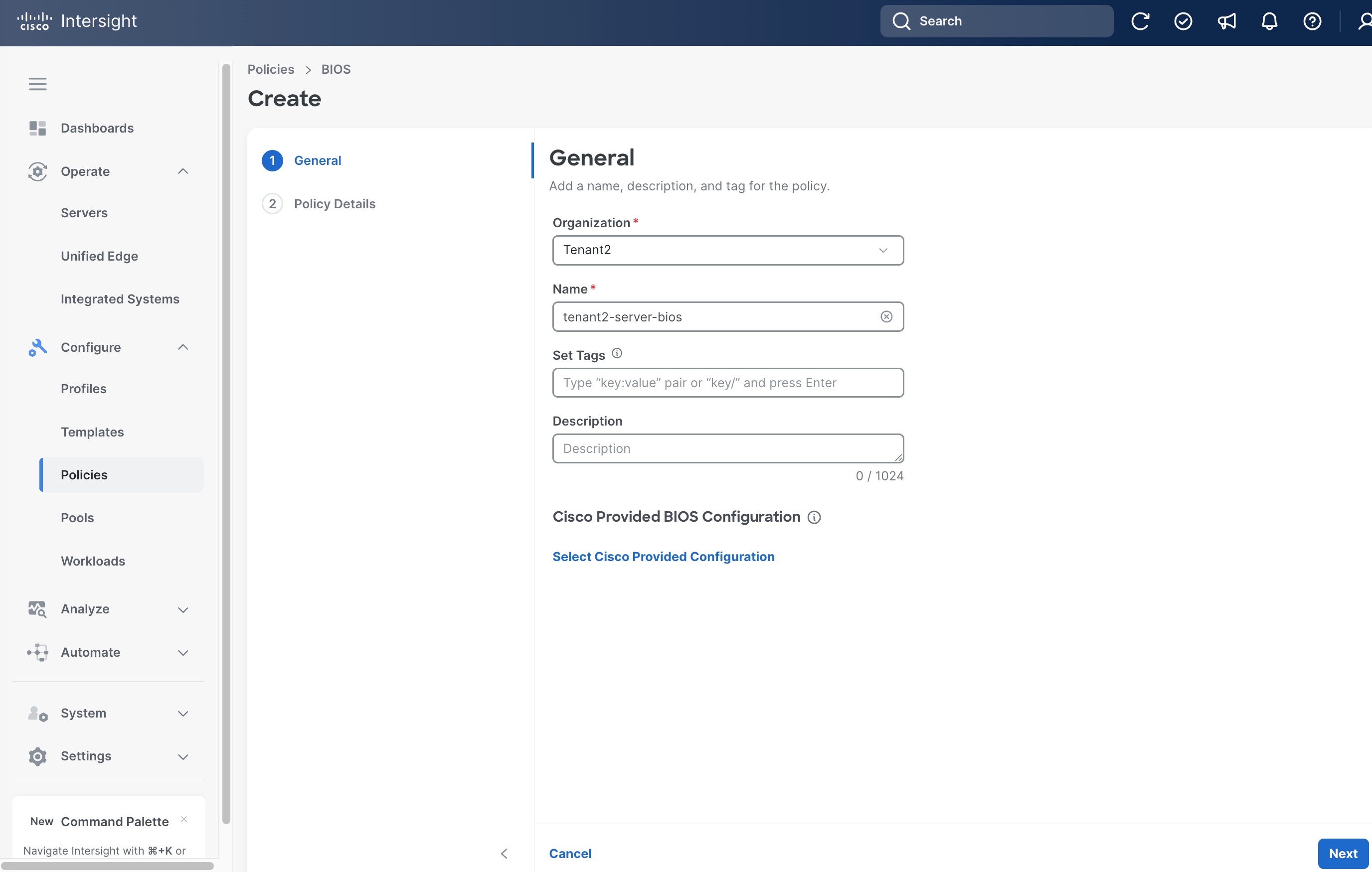
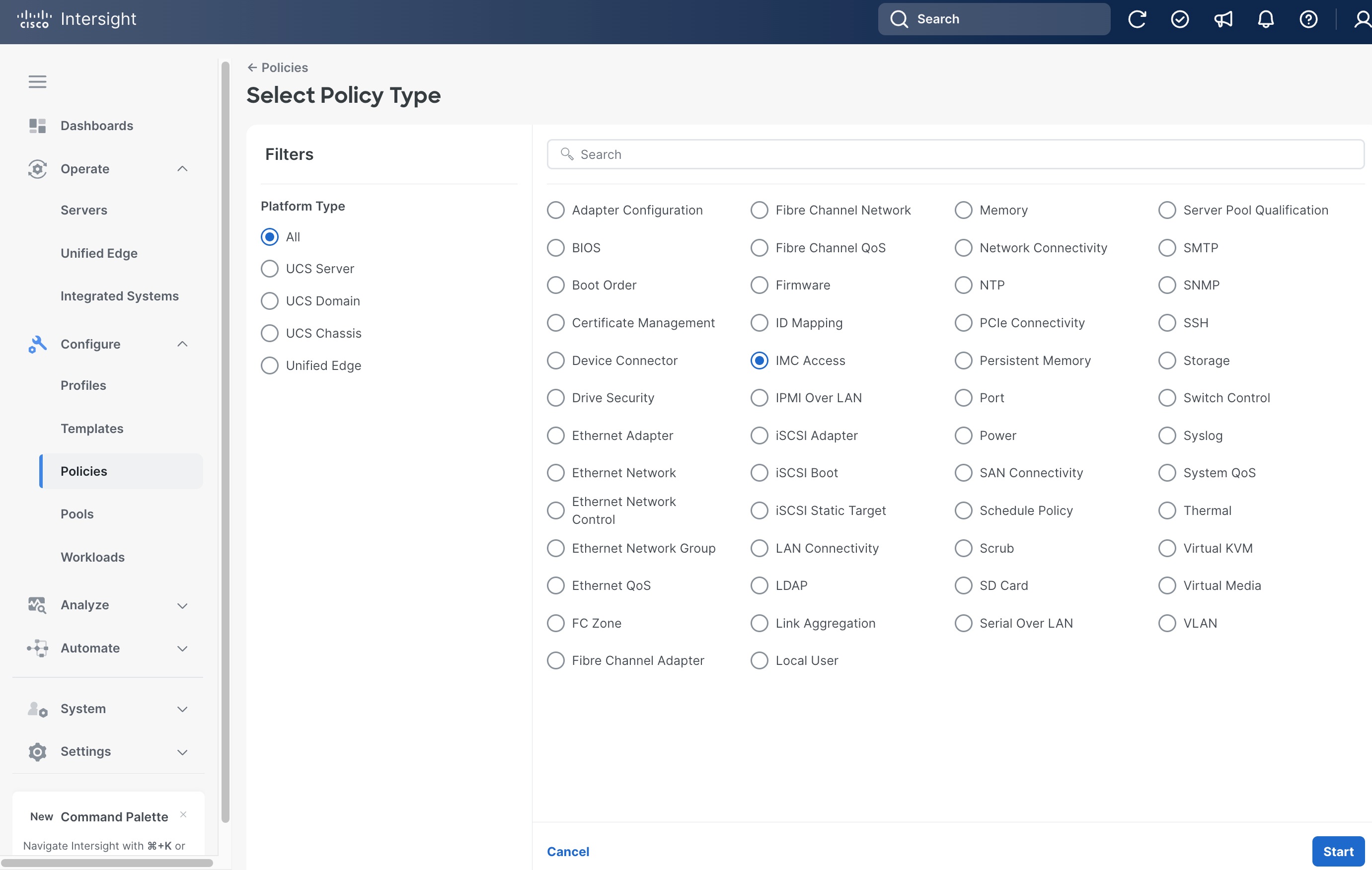
Procedure 3. Create BIOS Policy
Step 1. Go to Configure > Policies and then click Create Policy.
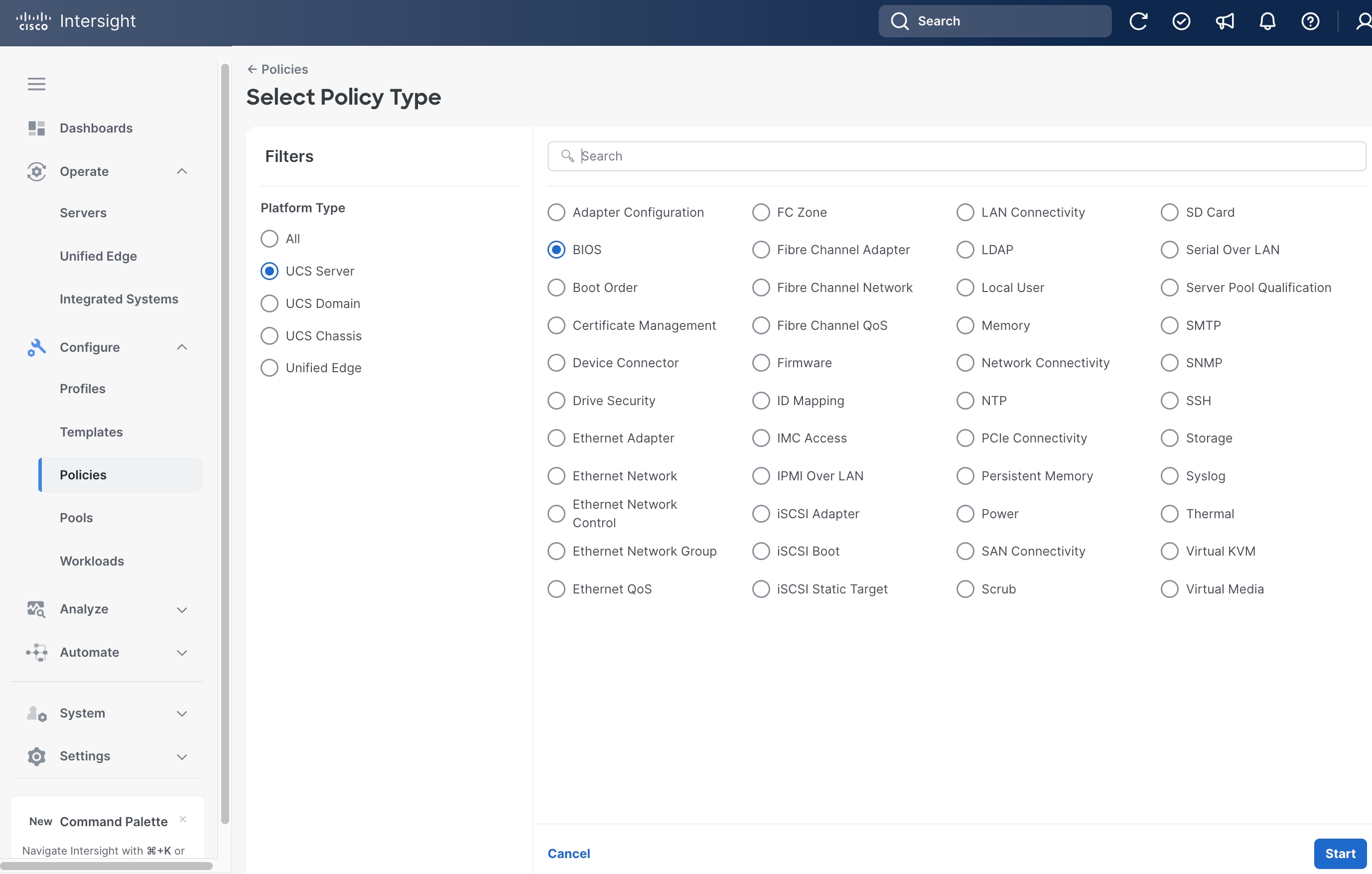
Step 2. On the Select Policy Type page, click UCS Server in the Filters section, then select BIOS.
Step 3. Click Start.
Step 4. On the General page, select the correct Organization, for example, Tenant2.
Step 5. Provide a Name for the policy, for example, tenant2-server-bios.
Step 6. (Optional) Provide Tags and Description.
Step 7. In the Cisco Provided BIOS Configuration section, click Select Cisco Provided Configuration.
Step 8. Search Virtualization-M8-Intel, then click Select.
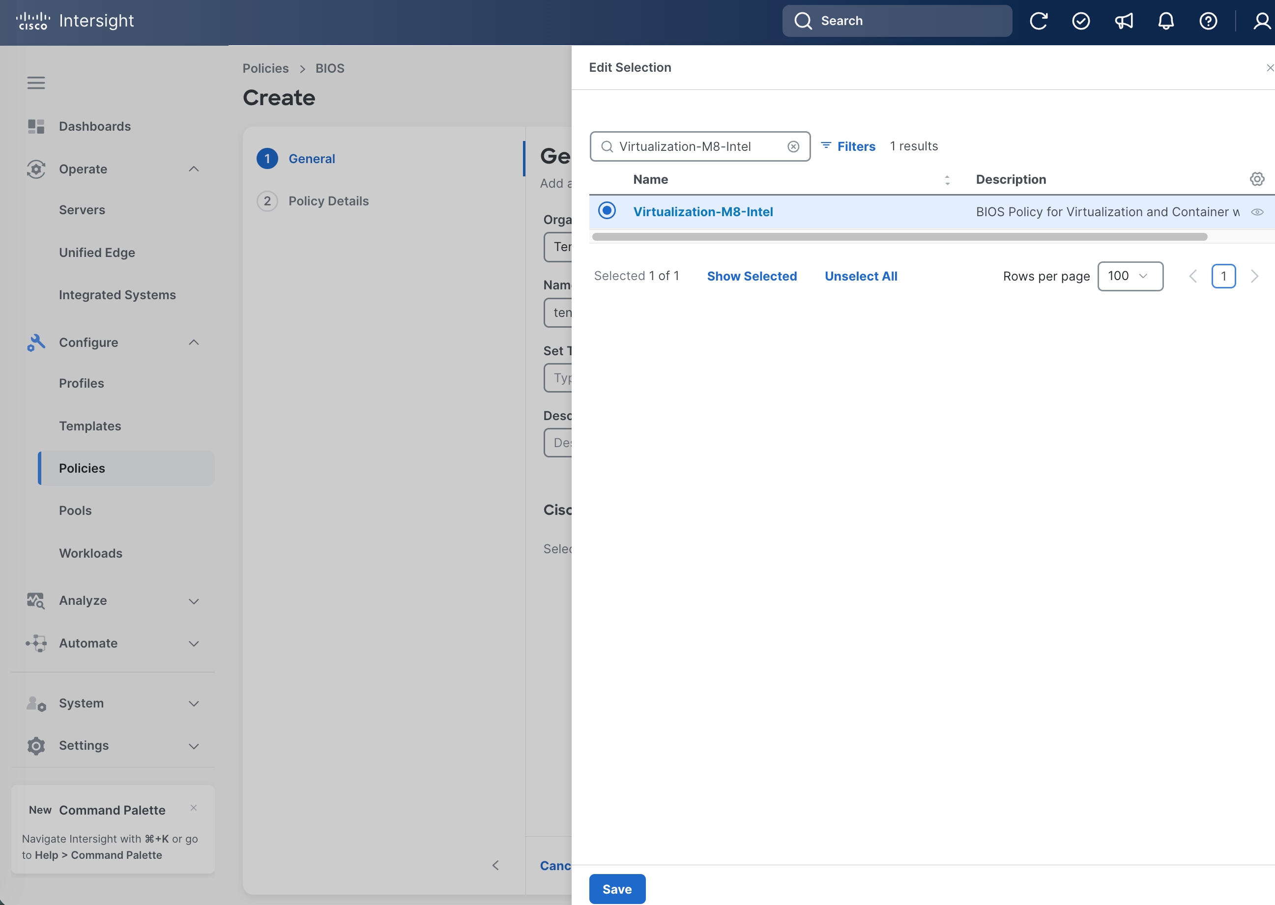
Step 9. From the General page, click Create.
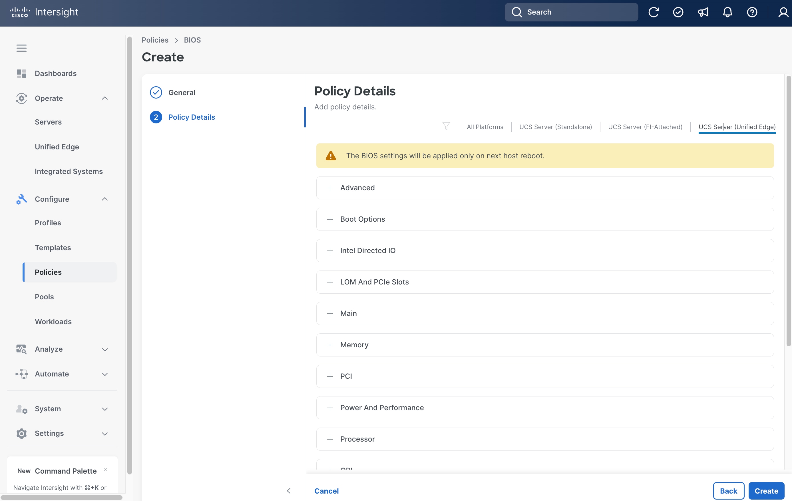
Step 10. In the Policy Details page, click UCS Server (Unified Edge).
Step 11. Click Create.
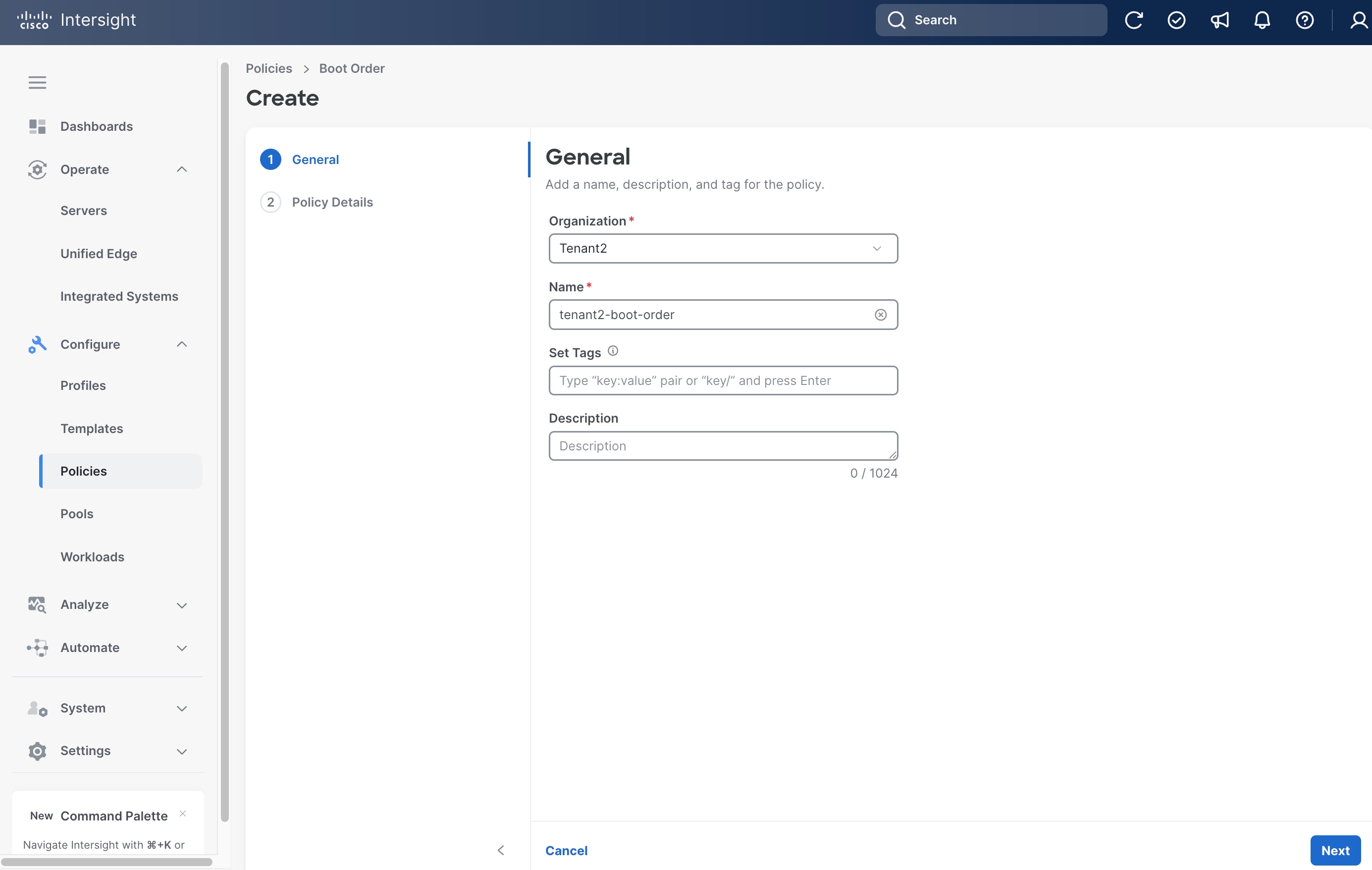
Procedure 4. Create Server Boot Order Policy
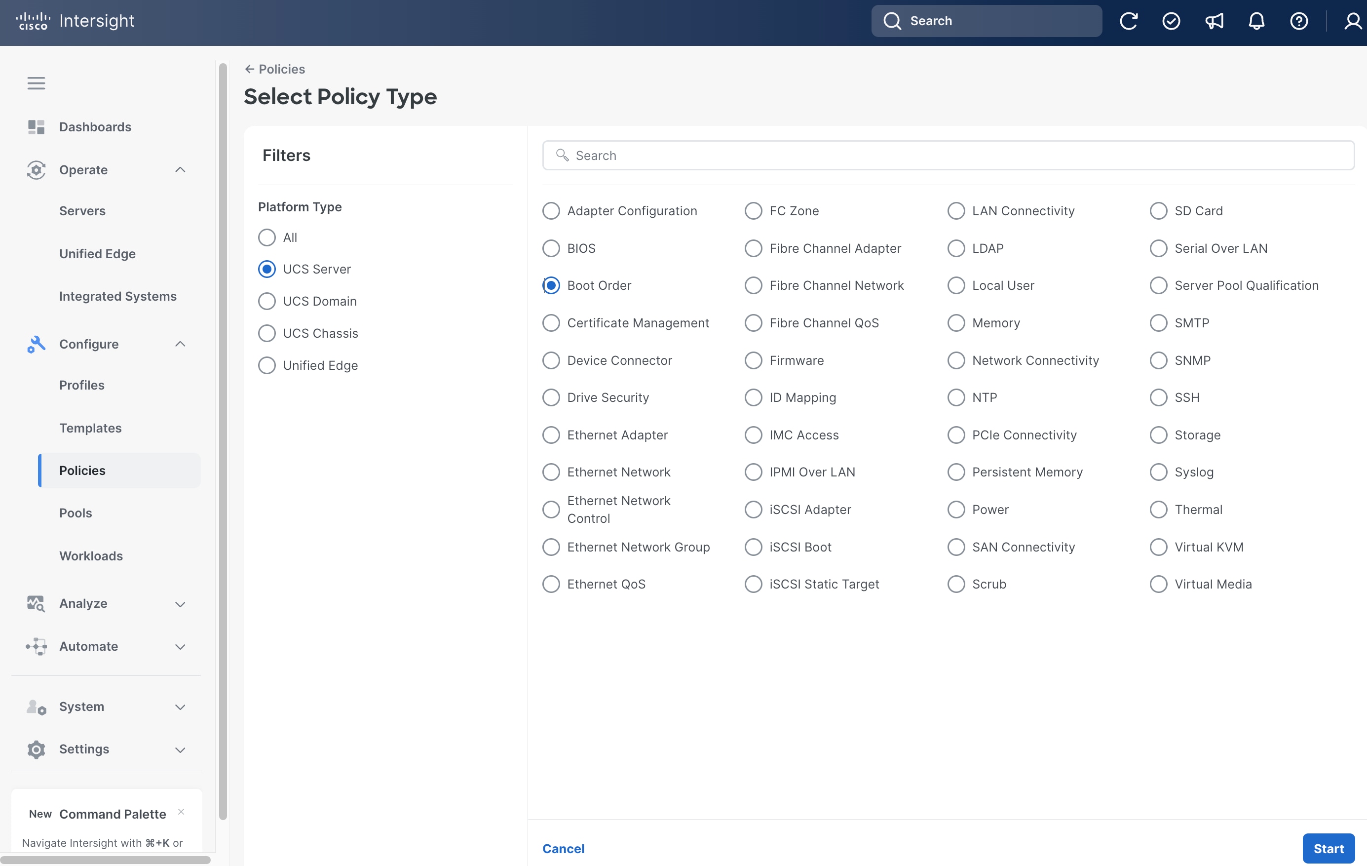
Step 1. Click Configure > Policies and then click Create Policy.
Step 2. On the Select Policy Type page, click UCS Server in the Filters section, then select Boot Order.
Step 3. Click Start.
Step 4. On the General page, select the correct Organization, for example, Tenant2.
Step 5. Provide a Name for the policy, for example, tenant2-boot-order.
Step 6. (Optional) Provide Tags and Description.
Step 7. Click Next.
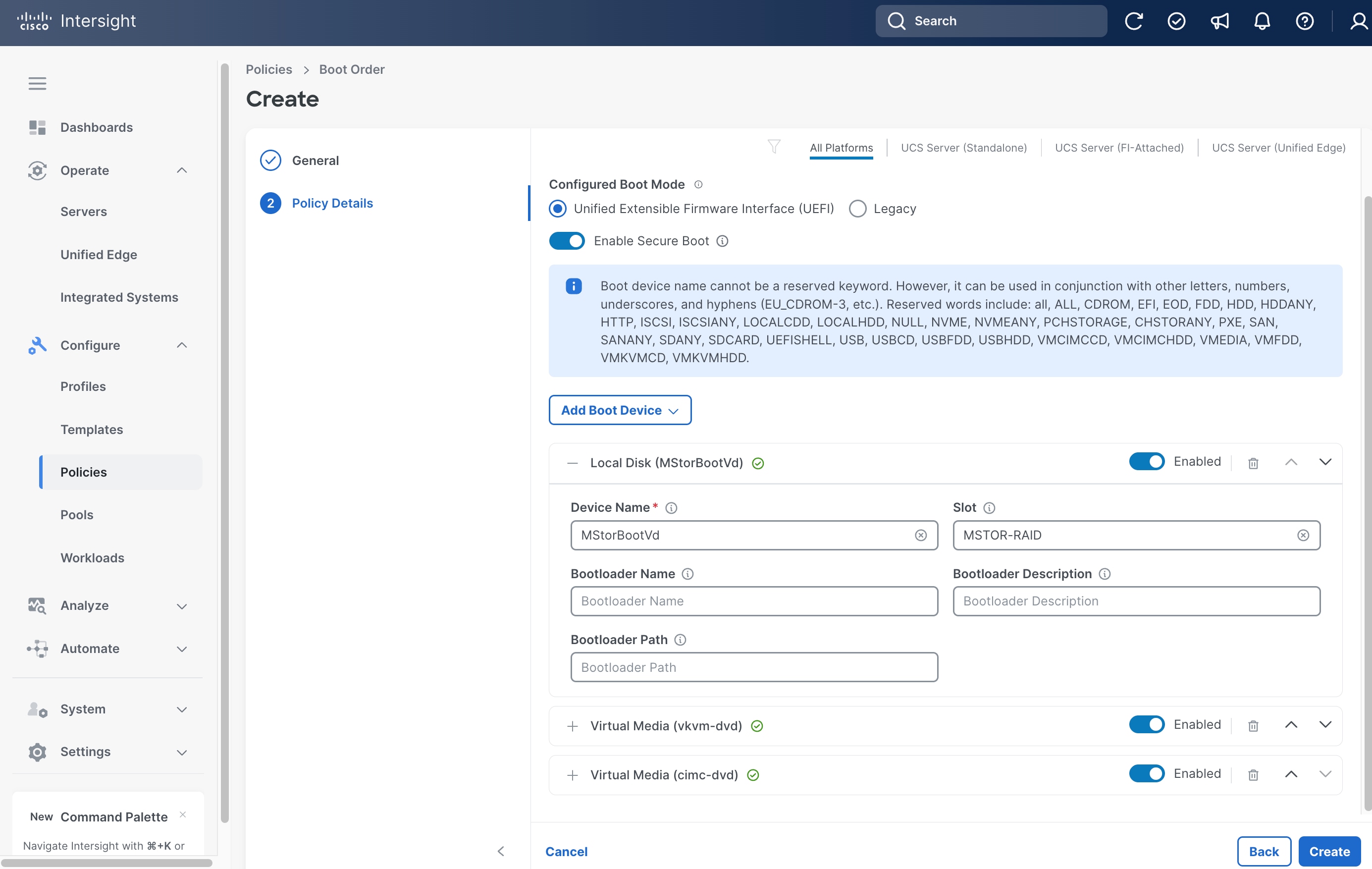
Step 8. On the Policy Details page, in the Configured Boot Mode section, select Unified Extensible Firmware Interface (UEFI).
Step 9. Configure Secure Boot based on your hardware configuration:
● If your server does NOT have an NVIDIA GPU: Toggle the switch ON to enable Secure Boot.
● If your server HAS an NVIDIA GPU: Leave Enable Secure Boot toggled OFF. Enabling Secure Boot on GPU-equipped servers will prevent NVIDIA drivers from loading, rendering the GPU inaccessible.
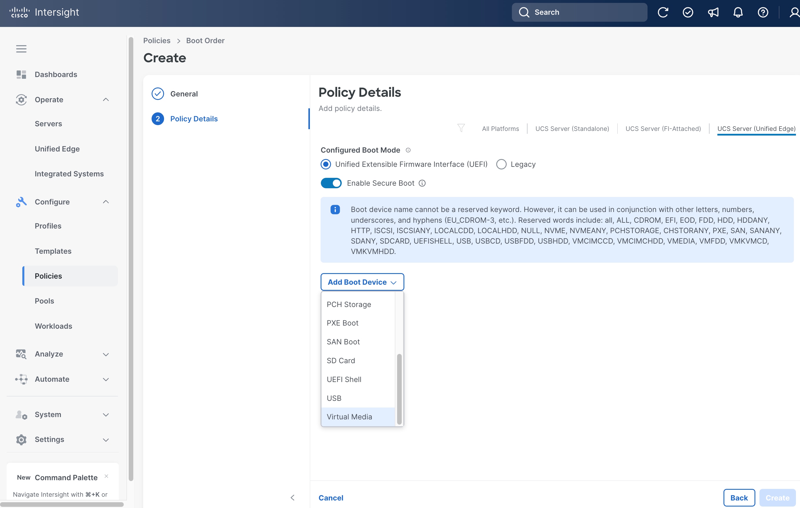
Step 10. From the Add Boot Device drop-down list, select Virtual Media.
Step 11. Set Device Name, for example, cimc-dvd, and choose CIMC MAPPED DVD as the Sub-Type.
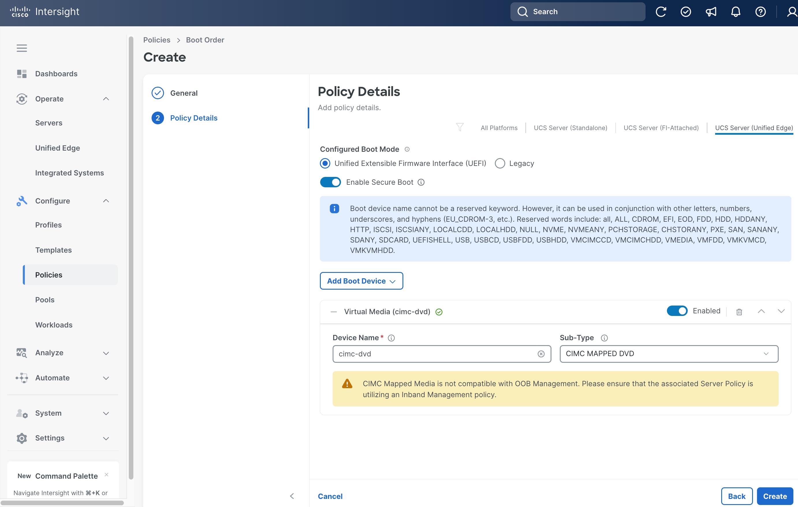
Step 12. From the Add Boot Device drop-down list, select Virtual Media again.
Step 13. Set Device Name, for example kvm-dvd, and choose KVM MAPPED DVD as the Sub-Type.
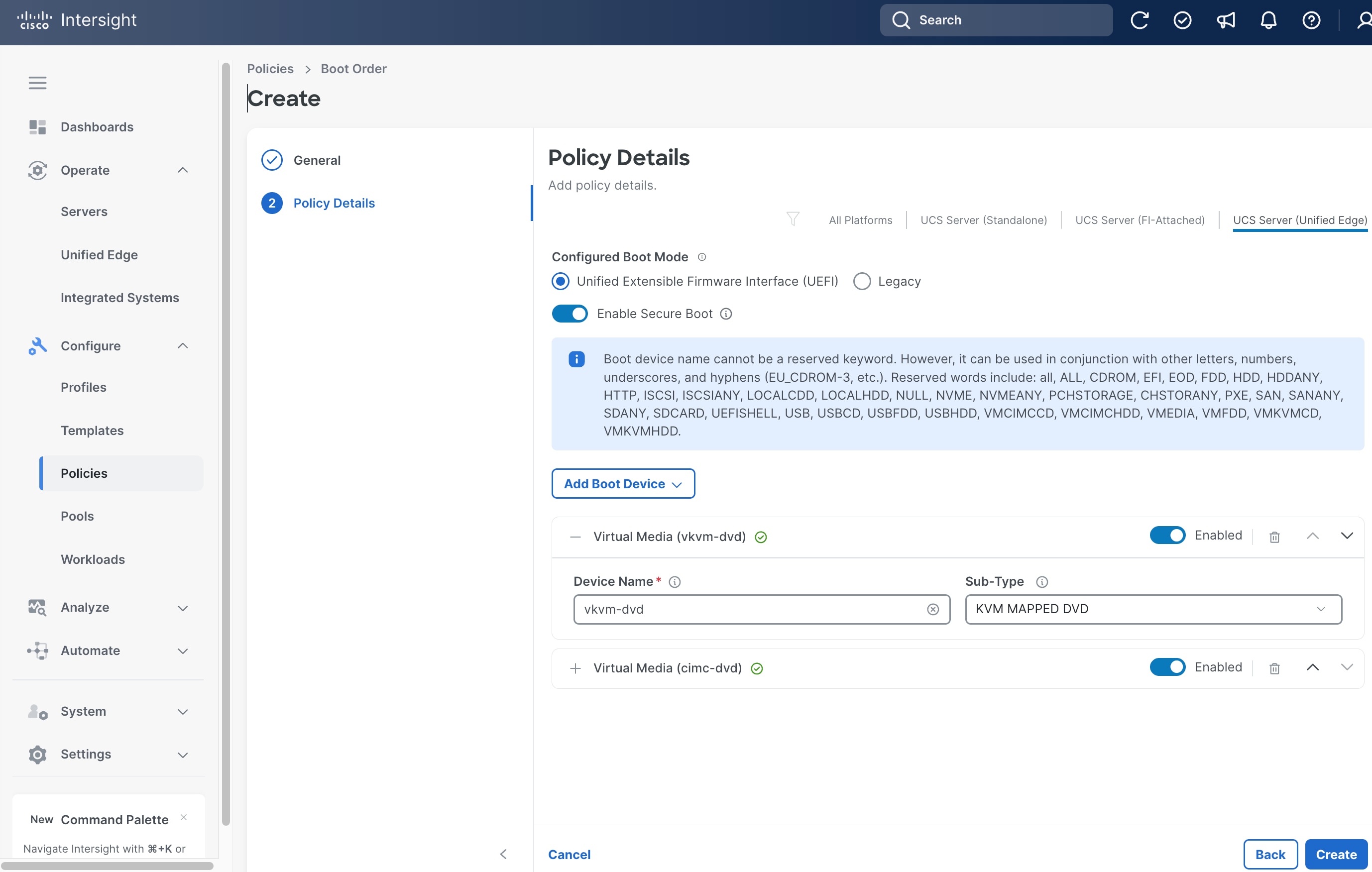
Step 14. From the Add Boot Device drop-down list, select Local Disk.
Step 15. In Local Disk section, enter MStorBootVd as the Device Name.
Step 16. In the Slot field, enter MSTOR-RAID.
Step 17. Click Create.
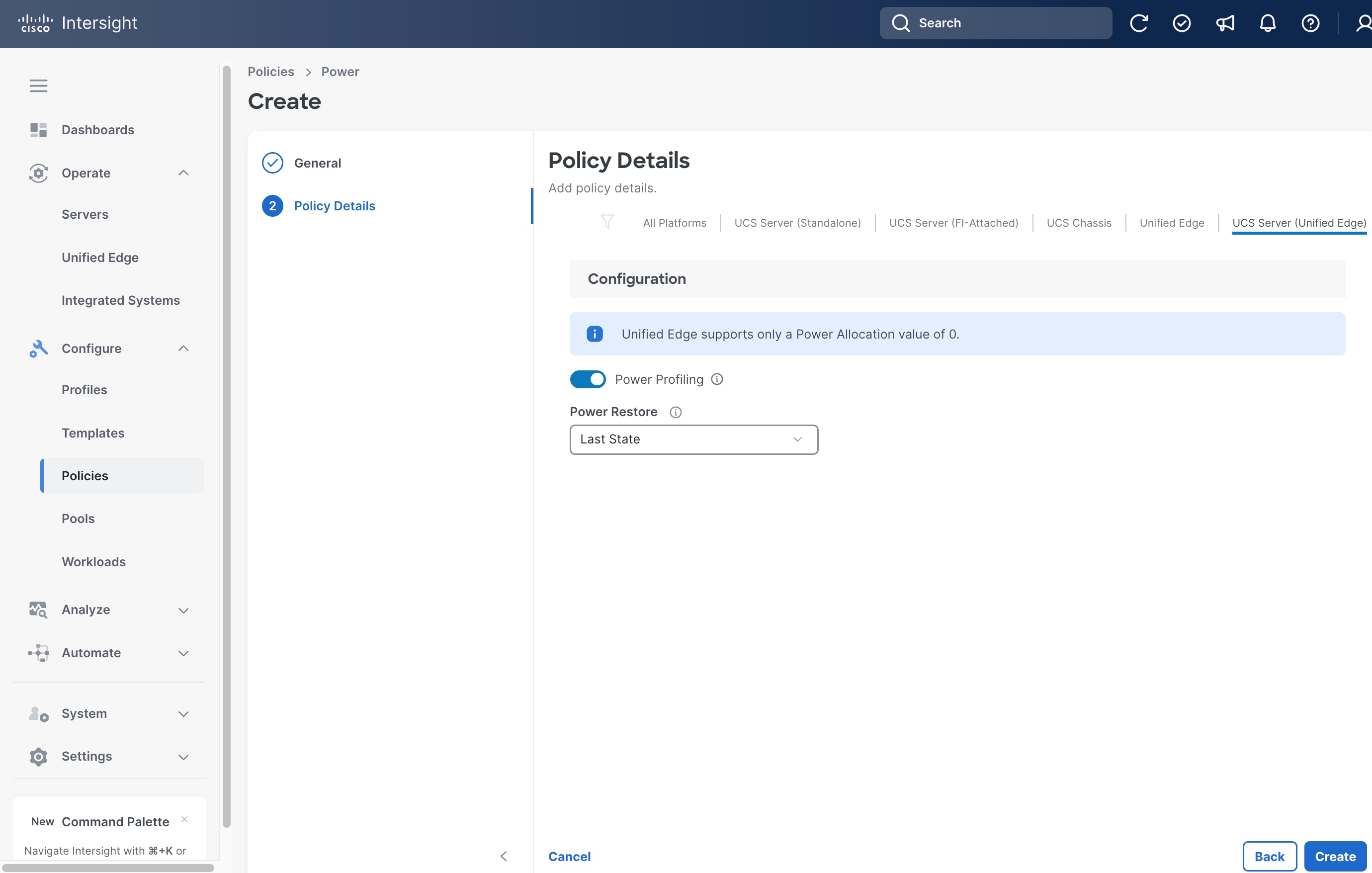
Procedure 5. Create Server Power Policy
Step 1. Click Configure > Policies and then click Create Policy.
Step 2. On the Select Policy Type page, click UCS Server in the Filters section, then select Power.
Step 3. Click Start.

Step 4. On the General page, select the correct Organization, for example, Tenant2.
Step 5. Provide a Name for the policy, for example, tenant2-server-power.
Step 6. (Optional) Provide Tags and Description.
Step 7. Click Next.

Step 8. On the Policy Details page, from the Power Restore drop-down list, select Last State.
Step 9. Click Create.
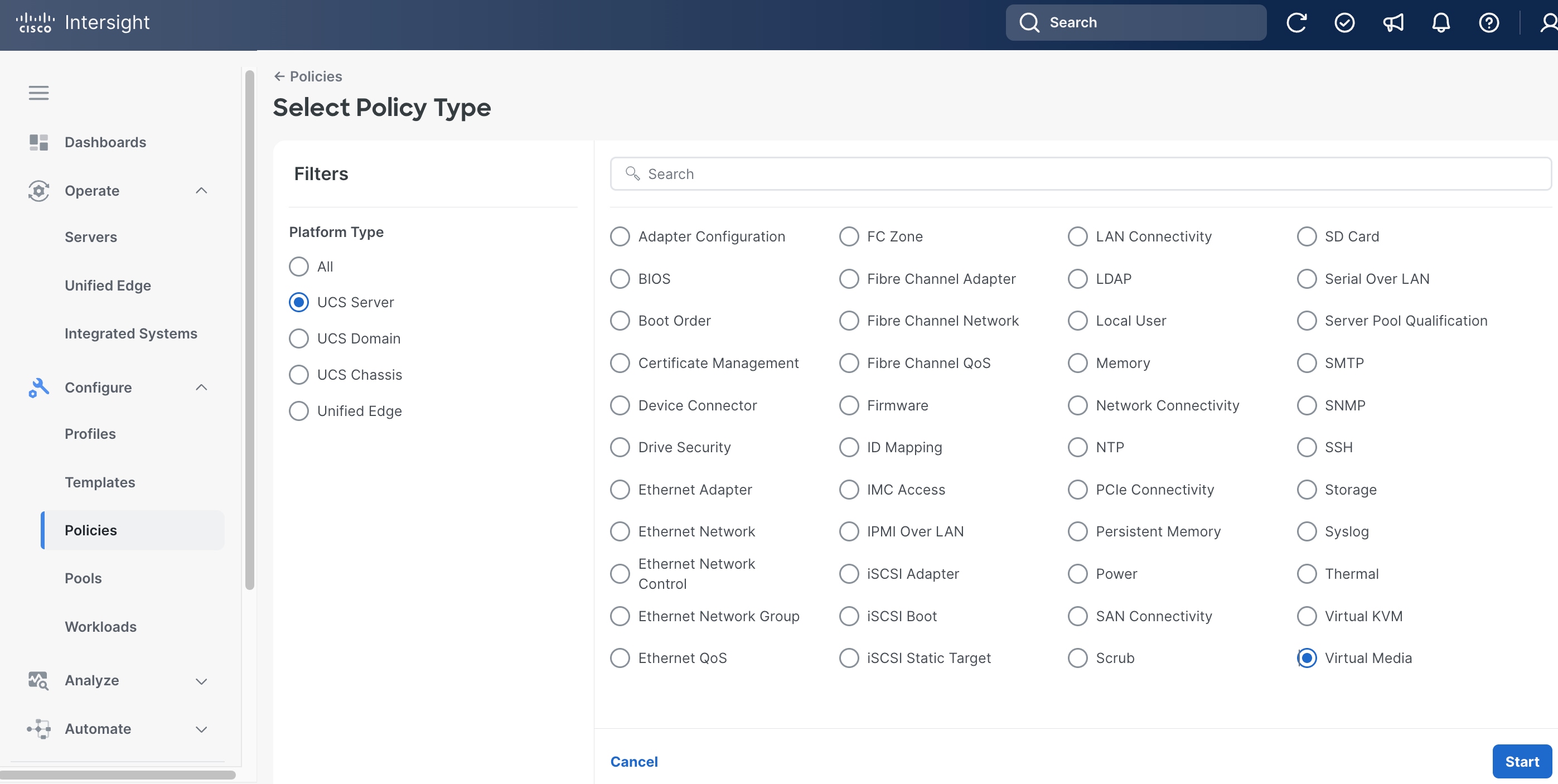
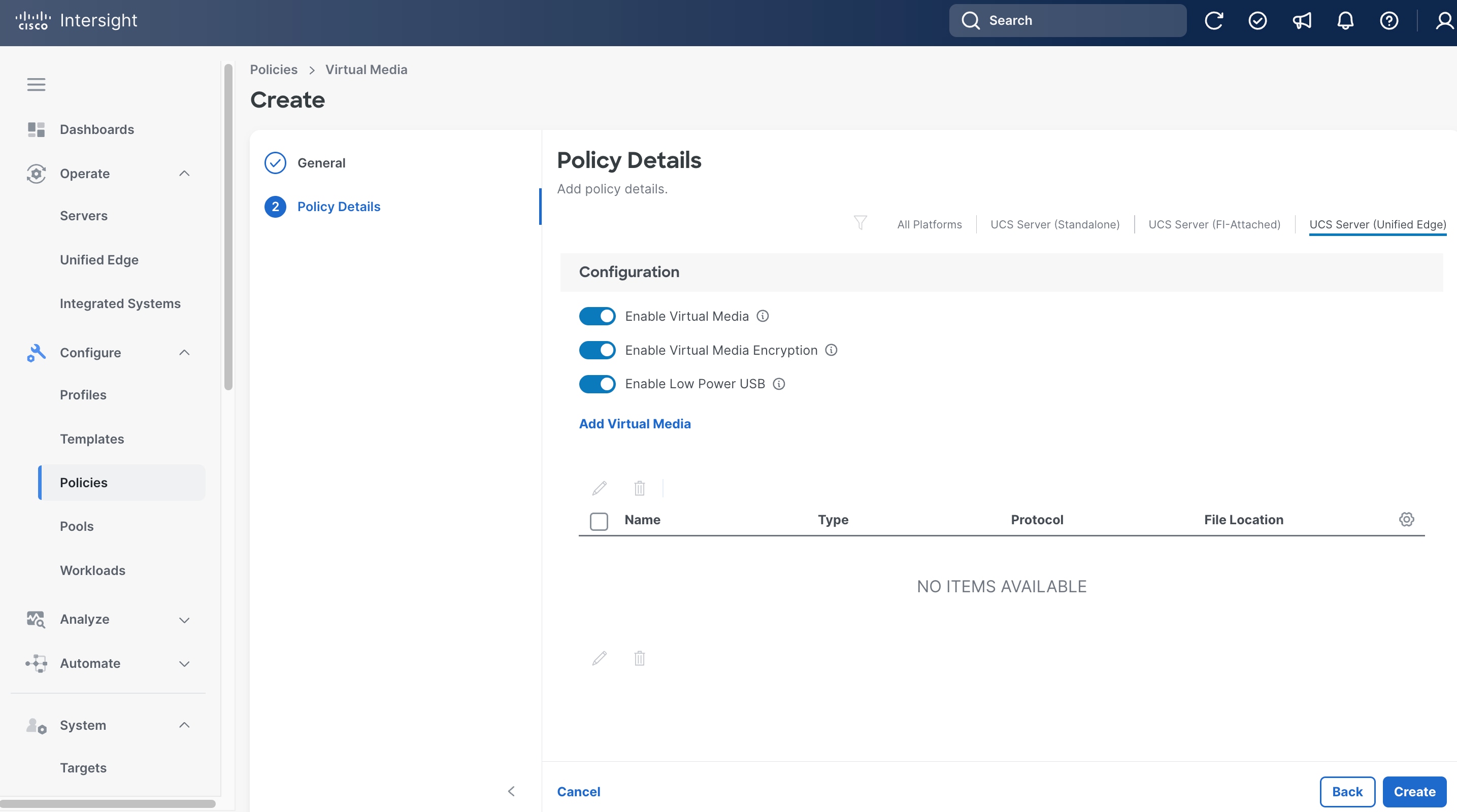
Procedure 6. Create Server Virtual Media Policy
Step 1. Click Configure > Policies and then click Create Policy.
Step 2. On the Select Policy Type page, click UCS Server in the Filters section, then select Virtual Media.
Step 3. Click Start.
Step 4. On the General page, select the correct Organization, for example, Tenant2.
Step 5. Provide a Name for the policy, for example, tenant2-vmedia-sno.
Step 6. (Optional) Provide Tags and Description.
Step 7. Click Next.
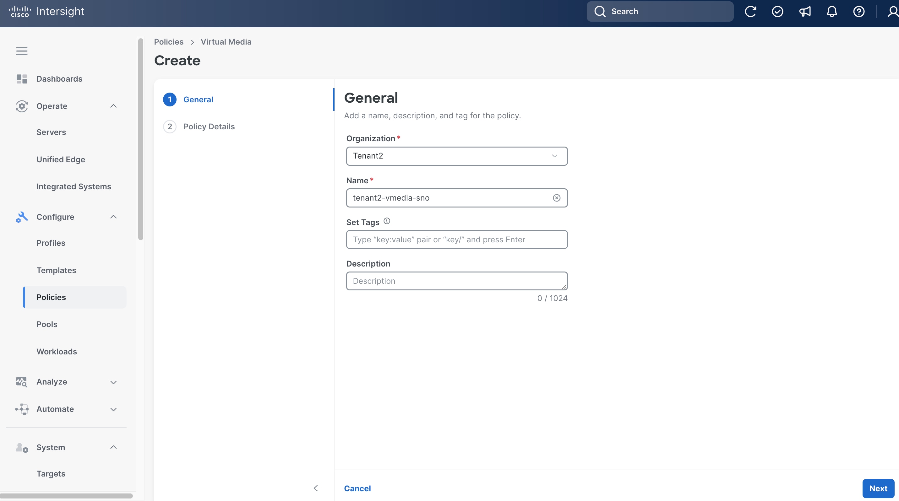
Step 8. Leave all fields at their default settings.
Step 9. Click Create.
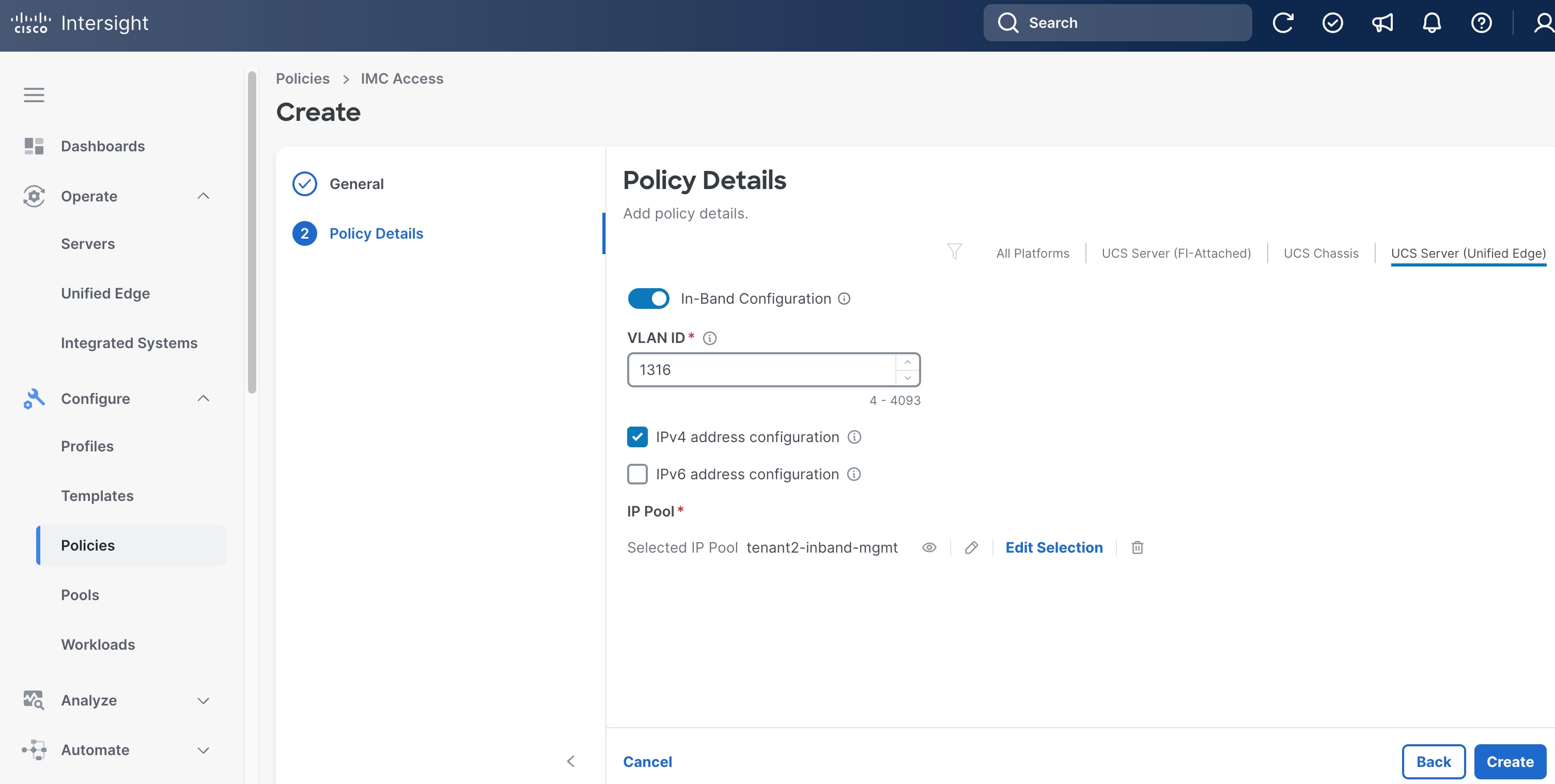
Procedure 7. Create Server IMC Access Policy
Step 1. Click Configure > Policies and then click Create Policy.
Step 2. On the Select Policy Type page, click UCS Server in the Filters section, then select IMC Access.
Step 3. Click Start.
Step 4. On the General page, select the correct Organization, for example, Tenant2.
Step 5. Provide a Name for the policy, for example, tenant2-imc.
Step 6. (Optional) Provide Tags and Description.
Step 7. Click Next.

Step 8. Click UCS Server (Unified Edge).
Step 9. Toggle the switch to enable In-Band Configuration and specify the VLAN ID for the purpose of in-band management, for example, VLAN 1316.
Step 10. In IP Pool section, select the IP Pool tenant2-inband-mgmt we created in the previous step.
Step 11. Click Create.
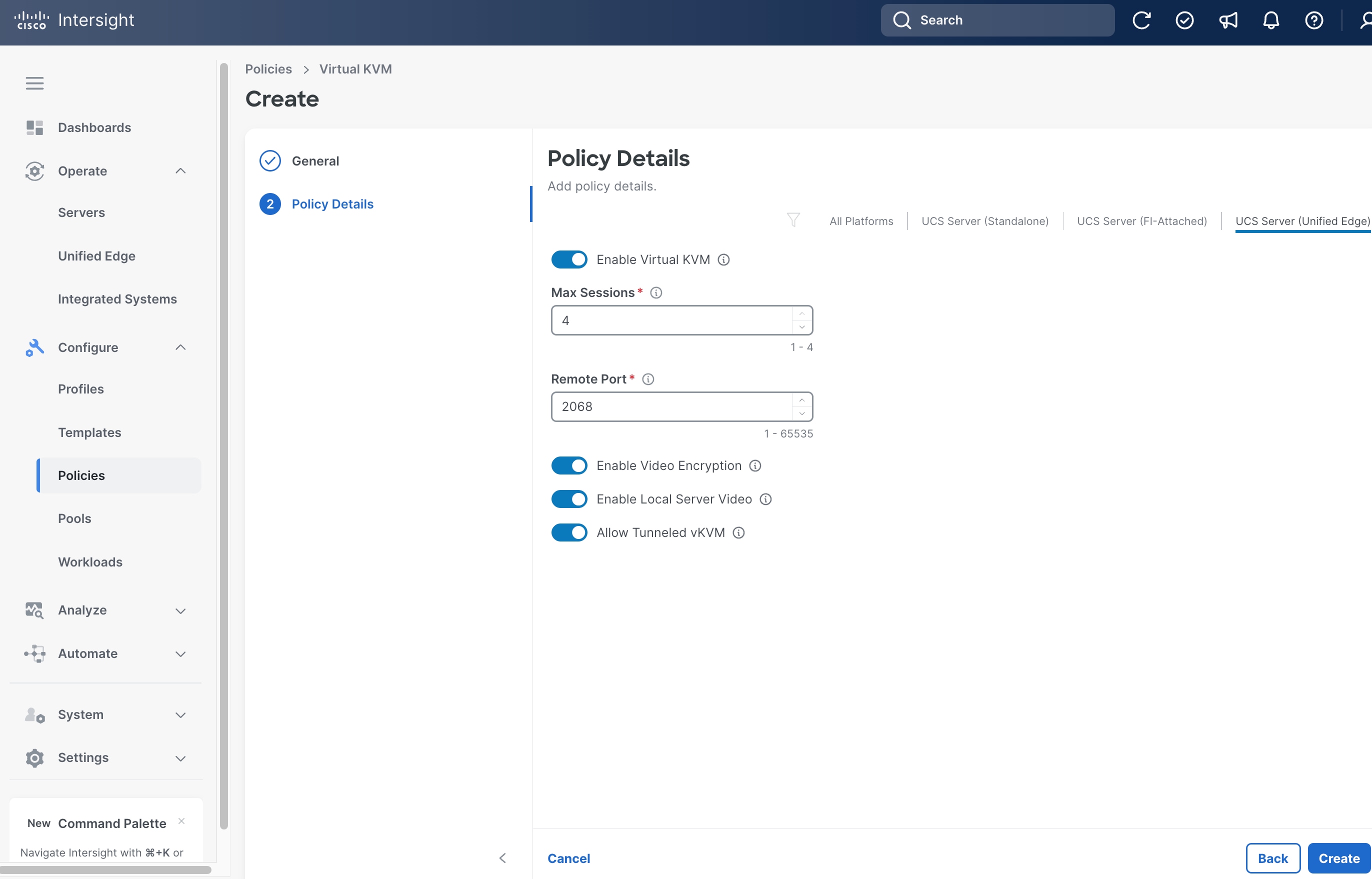
Procedure 8. Create Server Virtual KVM Policy
Step 1. Click Configure > Policies and then click Create Policy.
Step 2. On the Select Policy Type page, click UCS Server in the Filters section, then select Virtual KVM.
Step 3. Click Start.

Step 4. On the General page, select the correct Organization, for example, Tenant2.
Step 5. Provide a Name for the policy, for example, tenant2-vKVM.
Step 6. (Optional) Provide Tags and Description.
Step 7. Click Next.

Step 8. Click UCS Server (Unified Edge).
Step 9. Toggle the switch to enable Allow Tunneled vKVM. Leave all other fields at their default settings.
Step 10. Click Create.
Procedure 9. Create Server Storage Policy
Step 1. Click Configure > Policies and then click Create Policy.
Step 2. On the Select Policy Type page, click UCS Server in the Filters section, then select Storage.
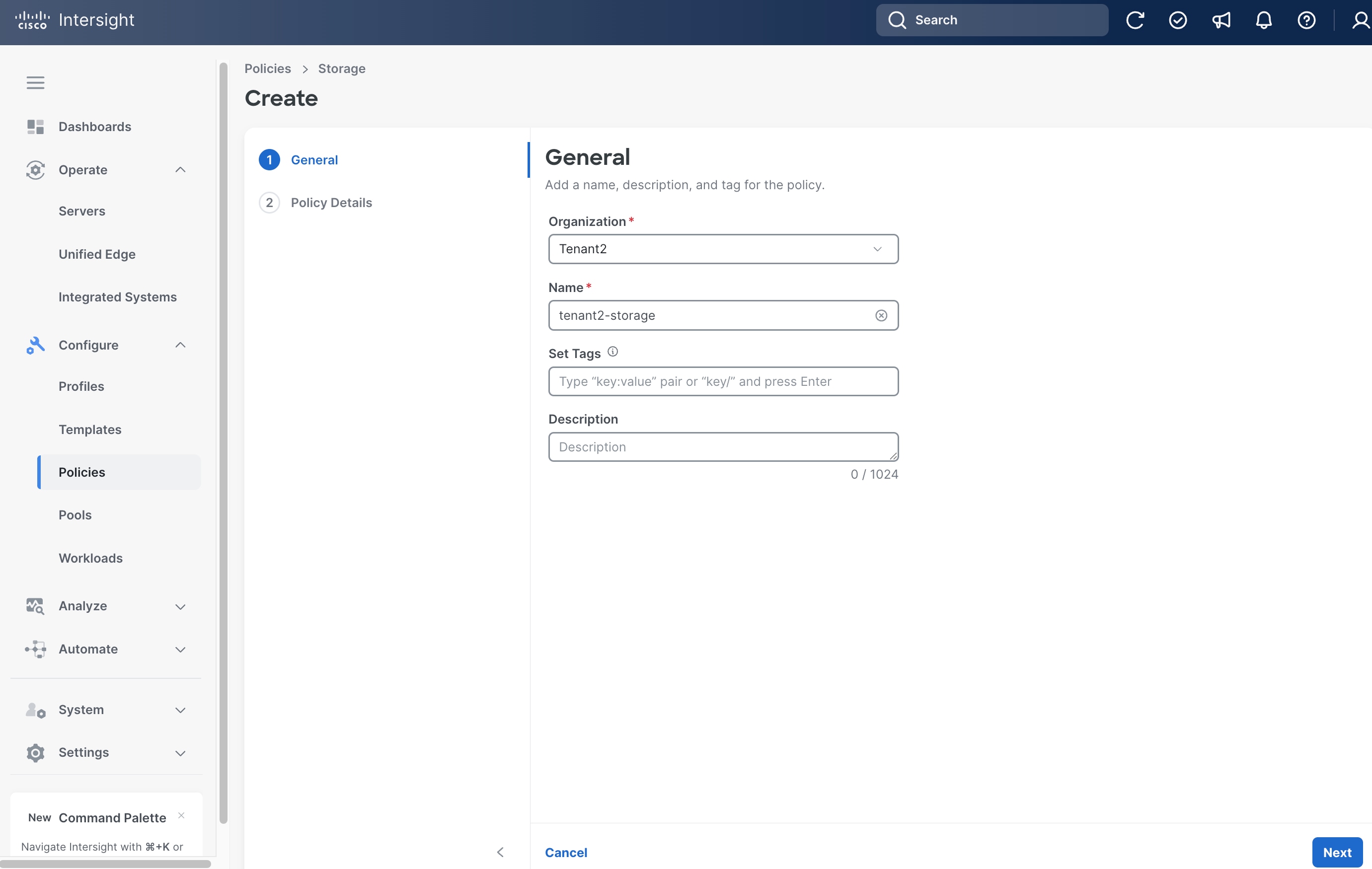
Step 3. Click Start.
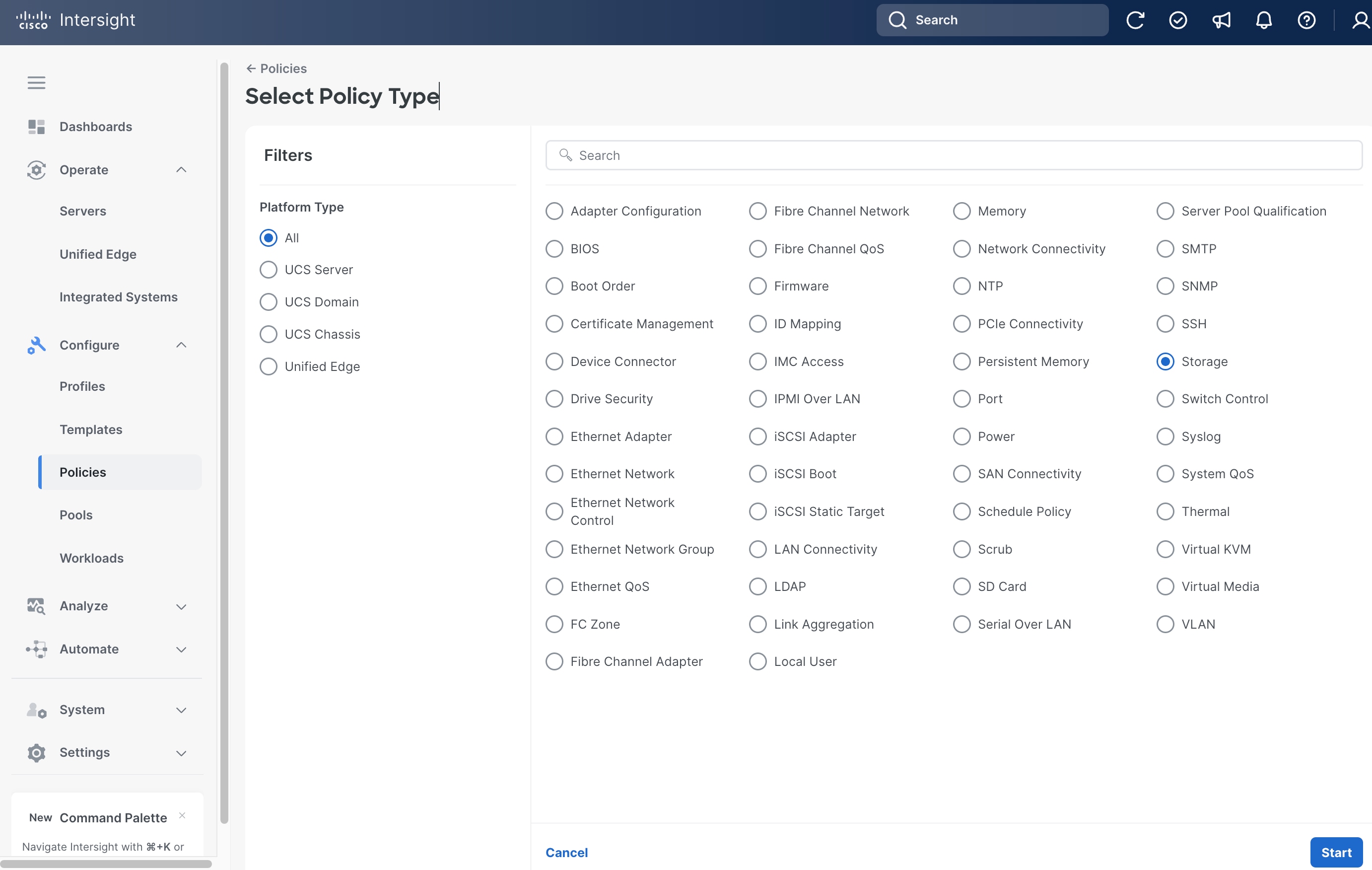
Step 4. On the General page, select the correct Organization, for example, Tenant2.
Step 5. Provide a Name for the policy, for example, tenant2-storage.
Step 6. (Optional) Provide Tags and Description.
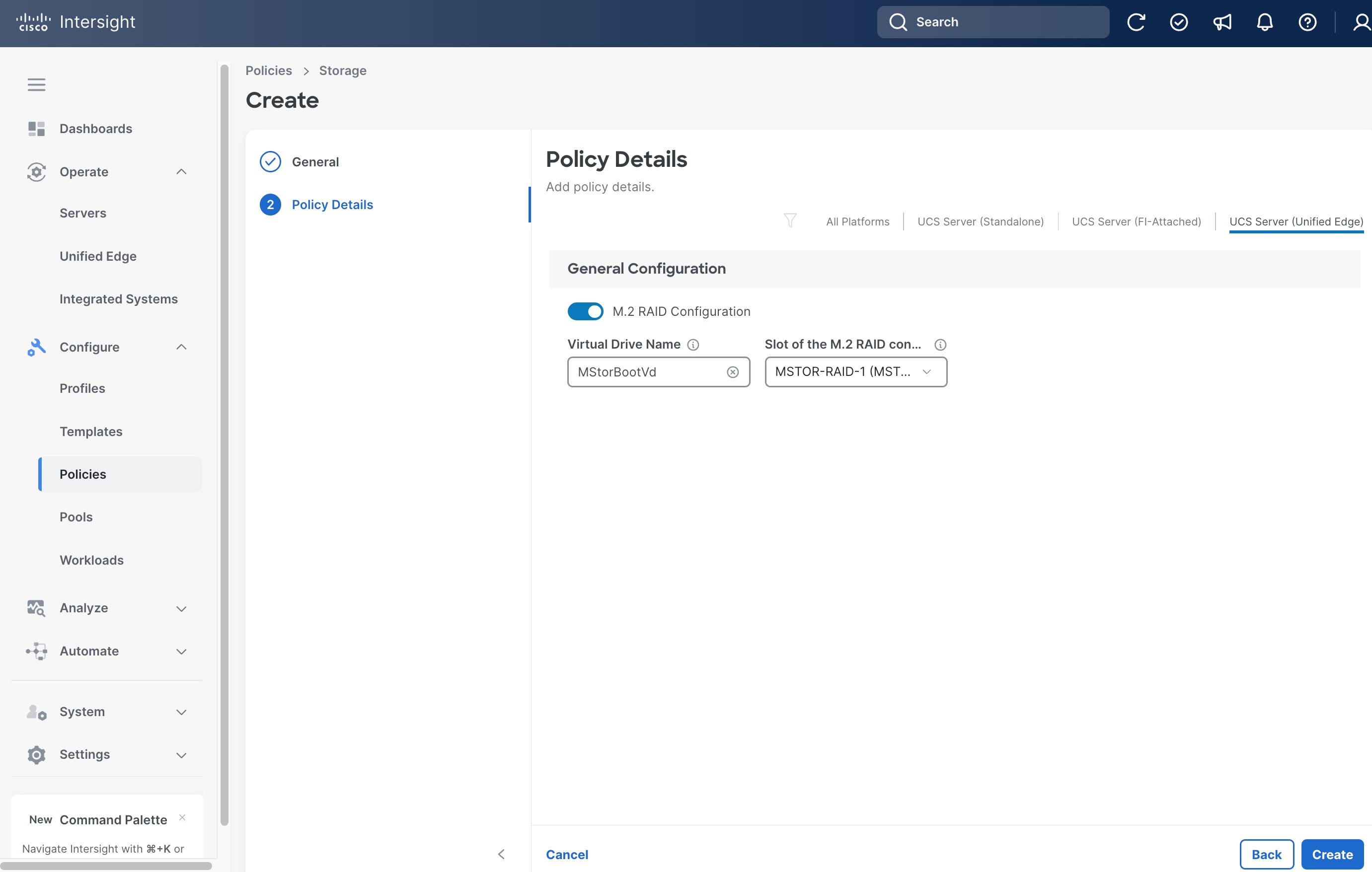
Step 7. Click Next.
Step 8. Click UCS Server (Unified Edge).
Step 9. Toggle the switch to enable M.2 RAID Configuration. Leave all fields at their default settings.
Step 10. Click Create.
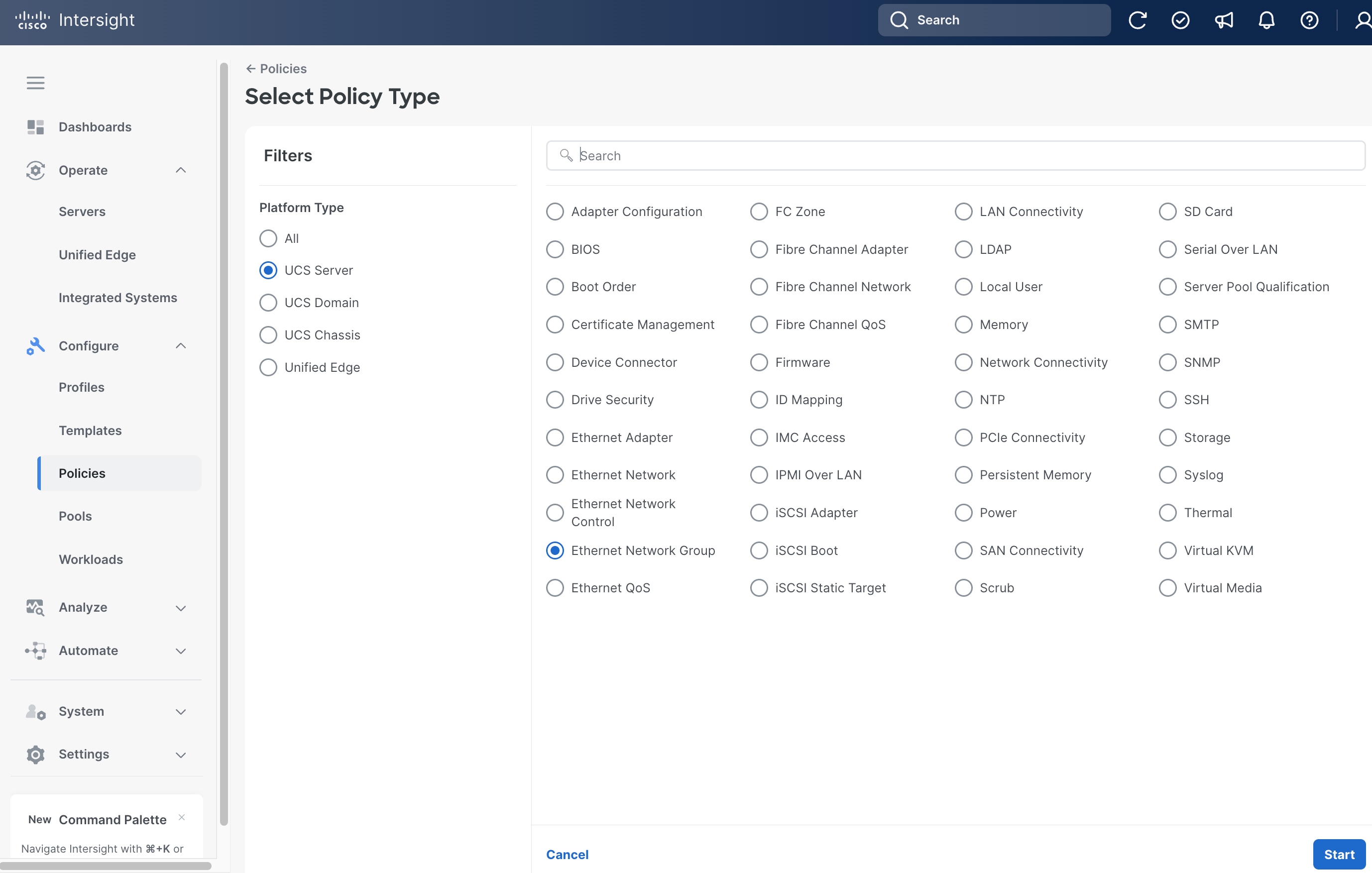
Procedure 10. Create Server Ethernet Network Group Policy
Step 1. Click Configure > Policies and then click Create Policy.
Step 2. On the Select Policy Type page, click UCS Server in the Filters section, then select Ethernet Network Group.
Step 3. Click Start.
Step 4. On the General page, select the correct Organization, for example, Tenant2.
Step 5. Provide a Name for the policy, for example, tenant2-eth-netgrp-sno.
Step 6. (Optional) Provide Tags and Description.
Step 7. Click Next.

Step 8. On the Policy Details page, click UCS Server (Unified Edge).
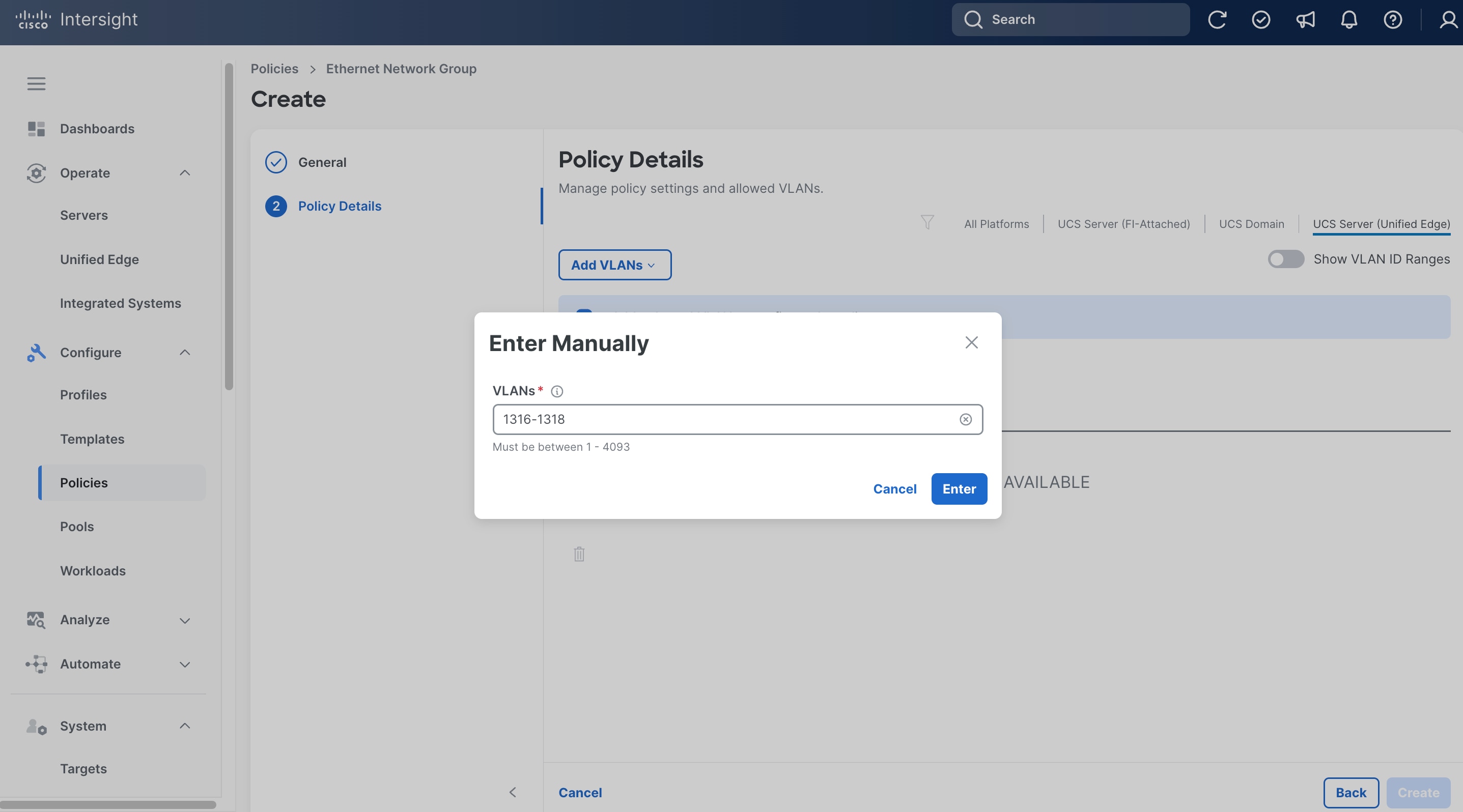
Step 9. From the Add VLANs drop-down list, choose Enter Manually.
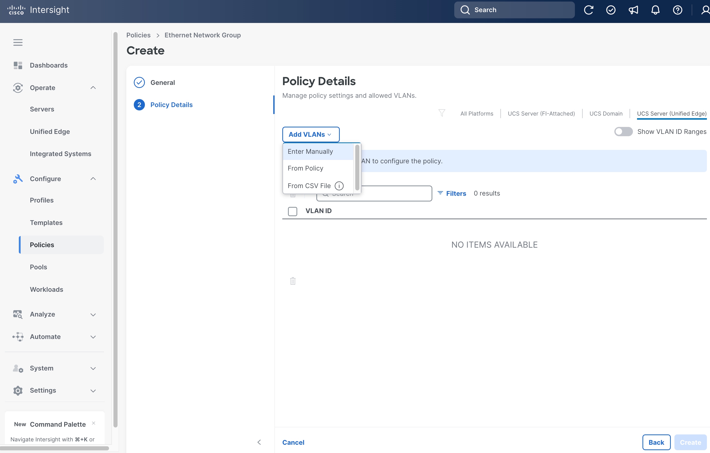
Step 10. Enter the VLAN range, for example, 1316-1318.
Step 11. Click Enter.
Step 12. From the Policy Details page, select the native VLAN id, for example, 1316, click the ellipses (…) at the end of the row, then from the drop-down list, click Set Native VLAN.
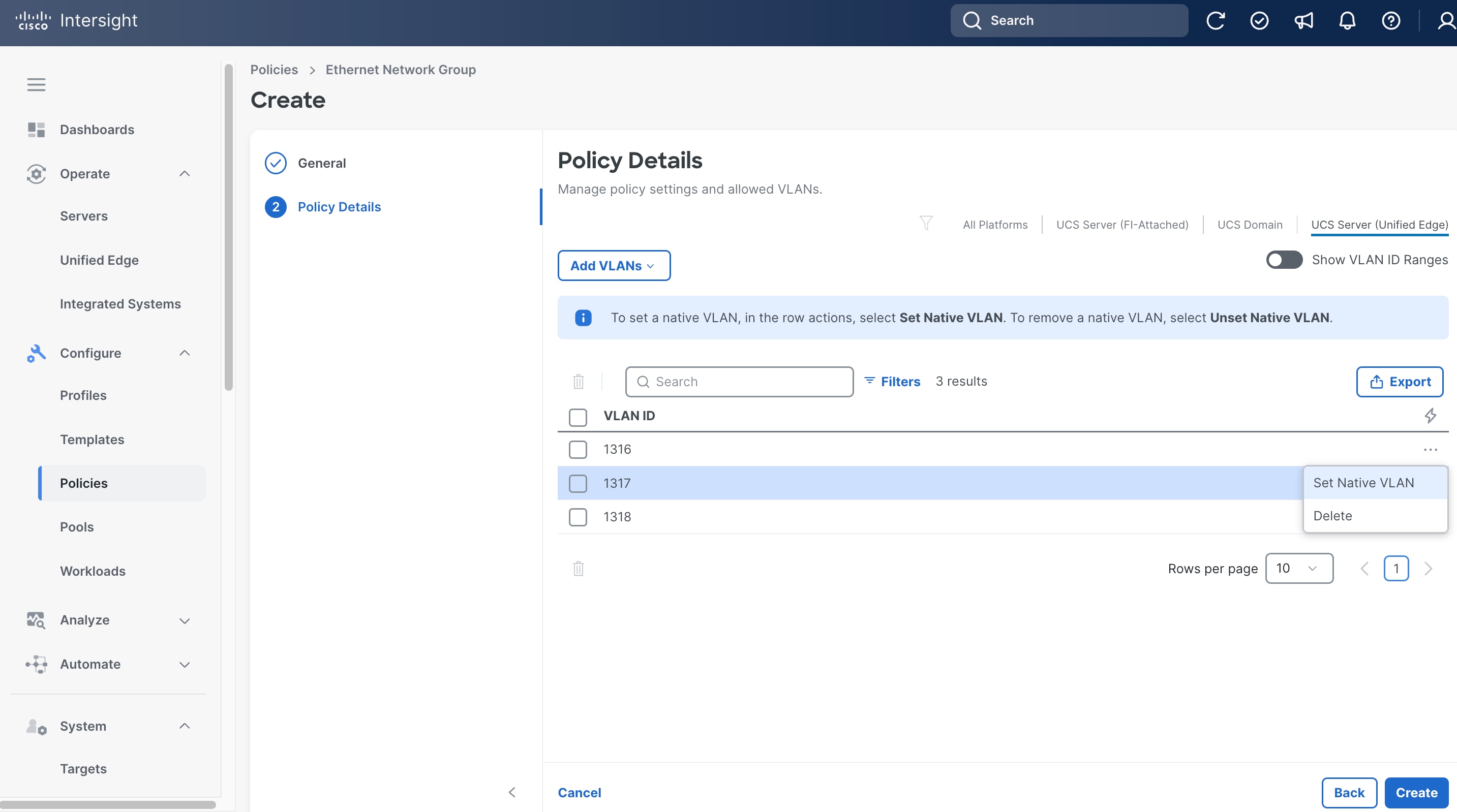
Step 13. Click Create.
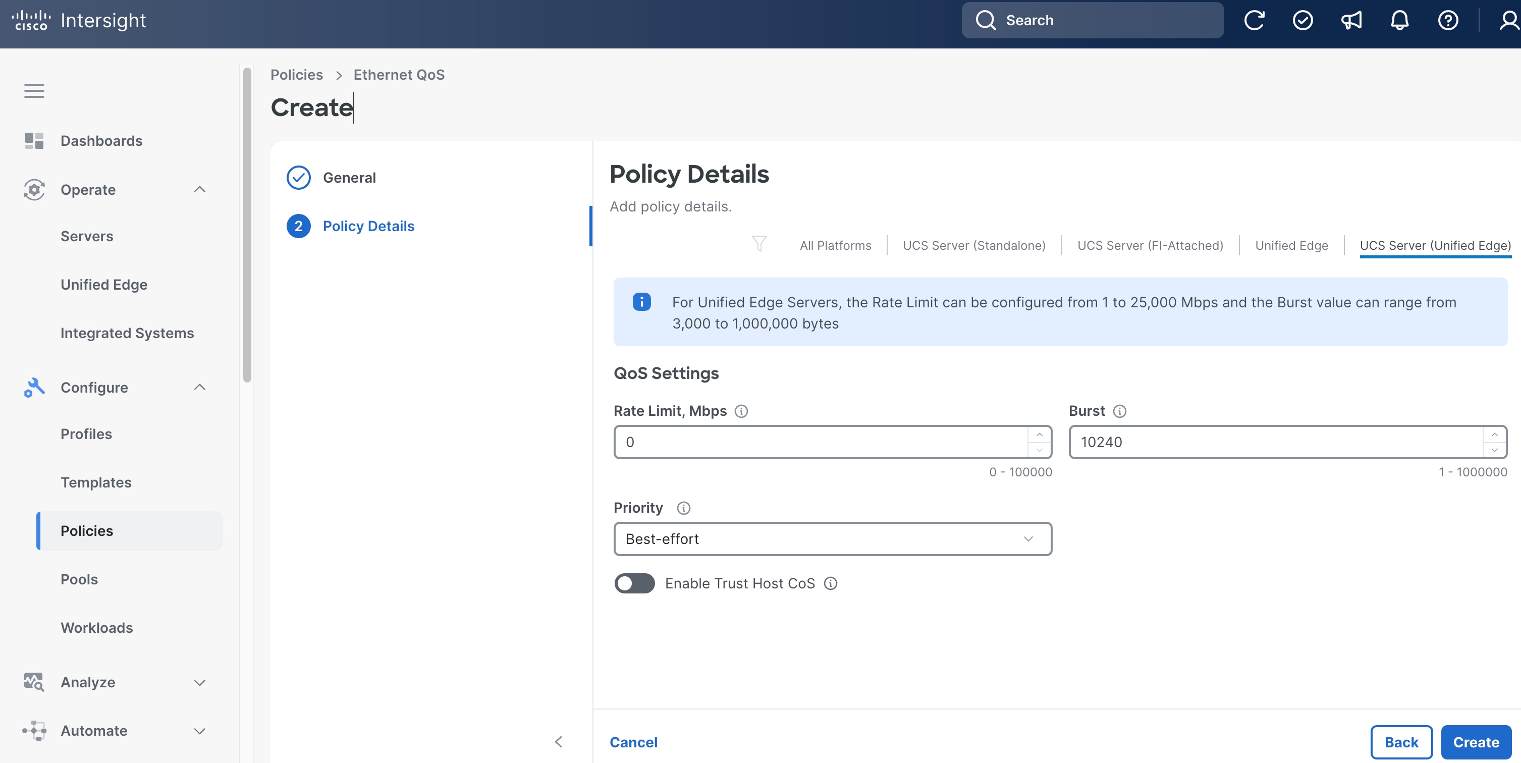
Procedure 11. Create Server Ethernet QoS Policy
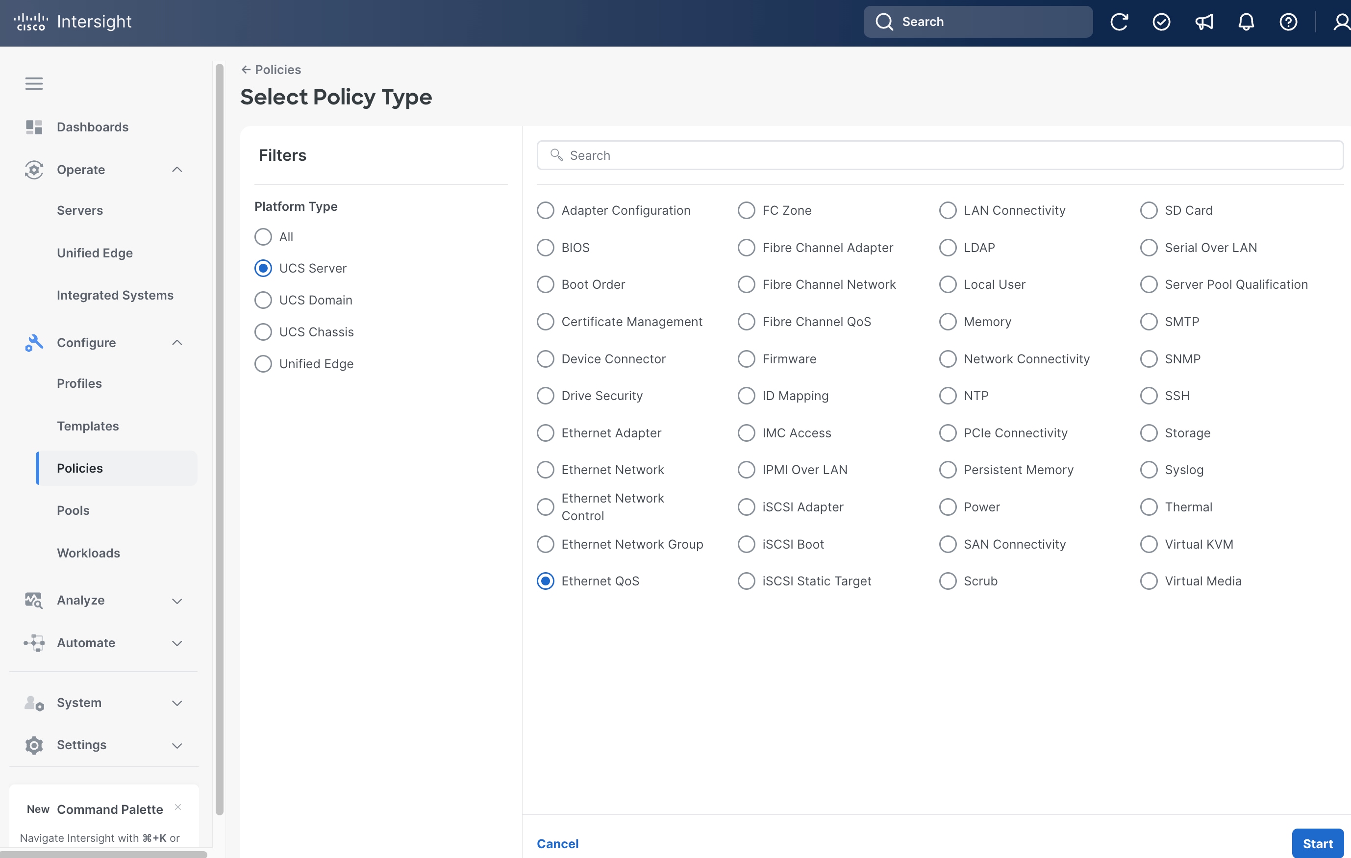
Step 1. Click Configure > Policies and then click Create Policy.
Step 2. On the Select Policy Type page, click UCS Server in the Filters section, then select Ethernet QoS.
Step 3. Click Start.
Step 4. On the General page, select the correct Organization, for example, Tenant2.
Step 5. Provide a Name for the policy, for example, tenant2-eth-qos.
Step 6. (Optional) Provide Tags and Description.
Step 7. Click Next.
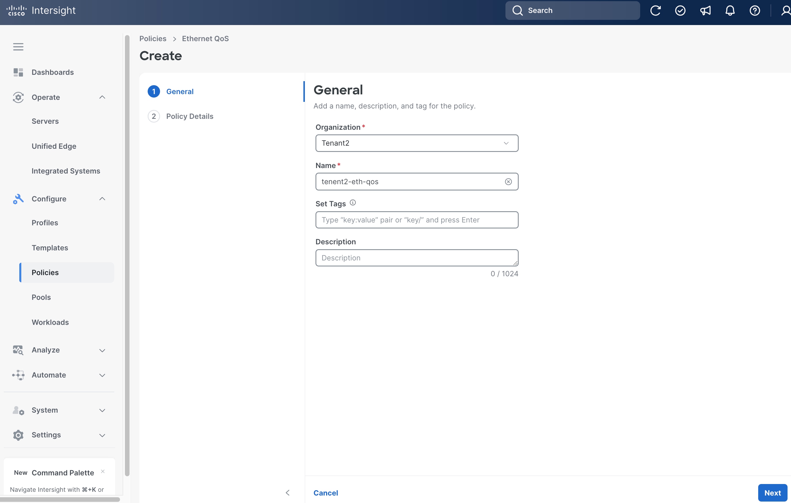
Step 8. On the Policy Details page, click UCS Server (Unified Edge).
Step 9. Leave all fields at their default settings, then click Create.
Procedure 12. Create Server LAN Connectivity Policy
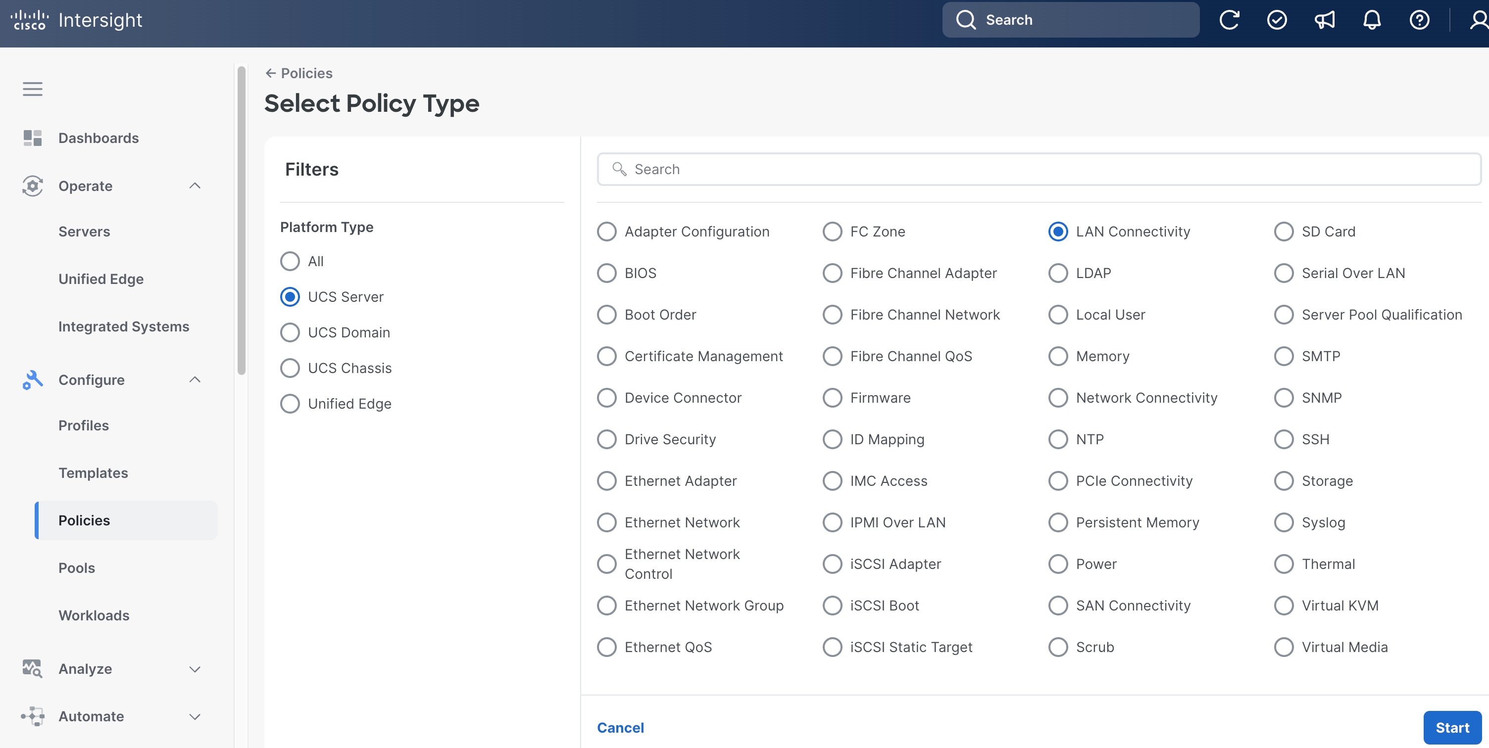
Step 1. Click Configure > Policies and then click Create Policy.
Step 2. On the Select Policy Type page, click UCS Server in the Filters section, then select LAN Connectivity.
Step 3. Click Start.
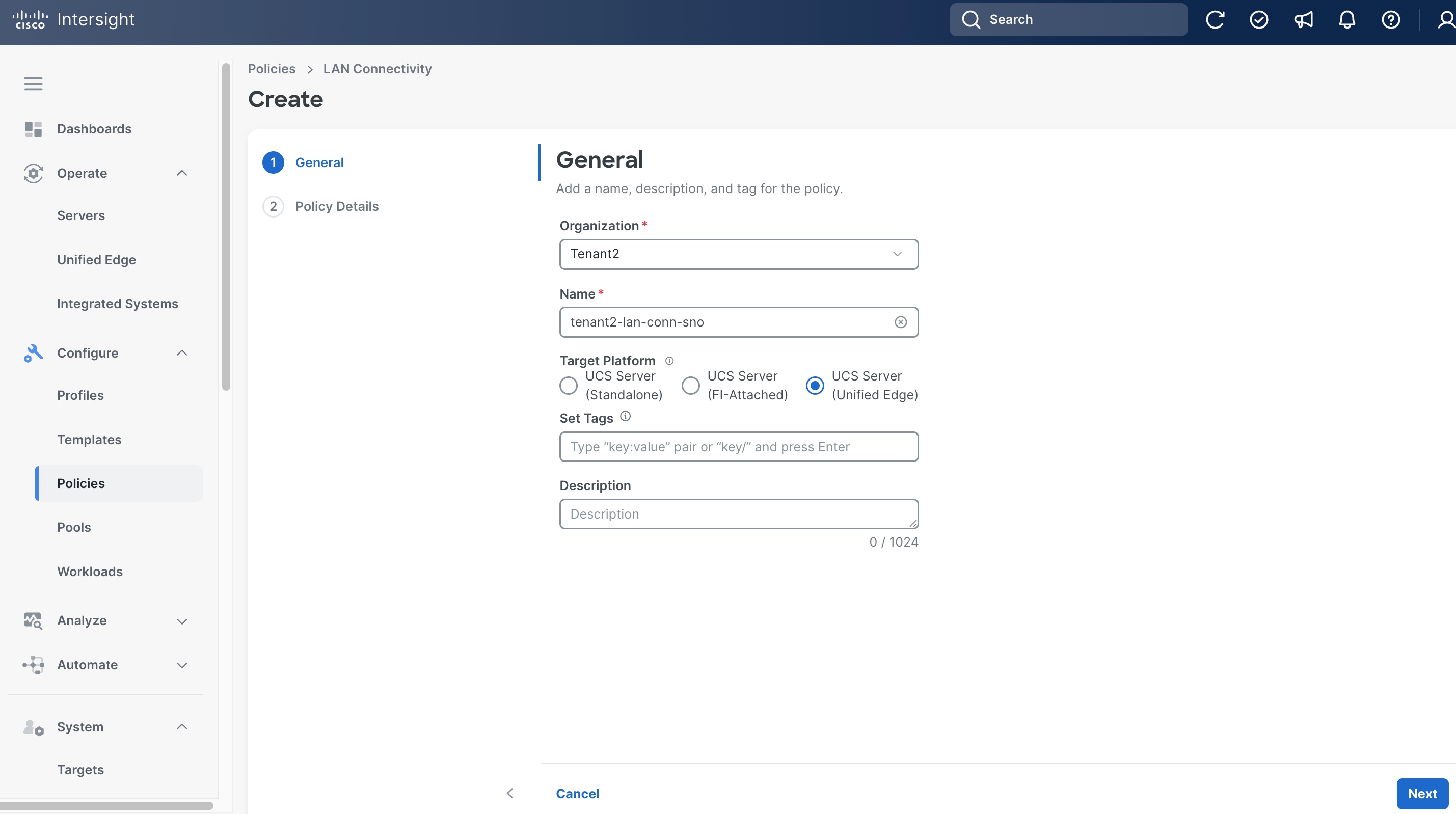
Step 4. On the General page, select the correct Organization, for example, Tenant2.
Step 5. Provide a Name for the policy, for example, tenant2-lan-conn-sno.
Step 6. Set Target Platform to UCS Server (Unified Edge).
Step 7. (Optional) Provide Tags and Description.
Step 8. Click Next.
Step 9. On the Policy Details page, click Add vNIC.
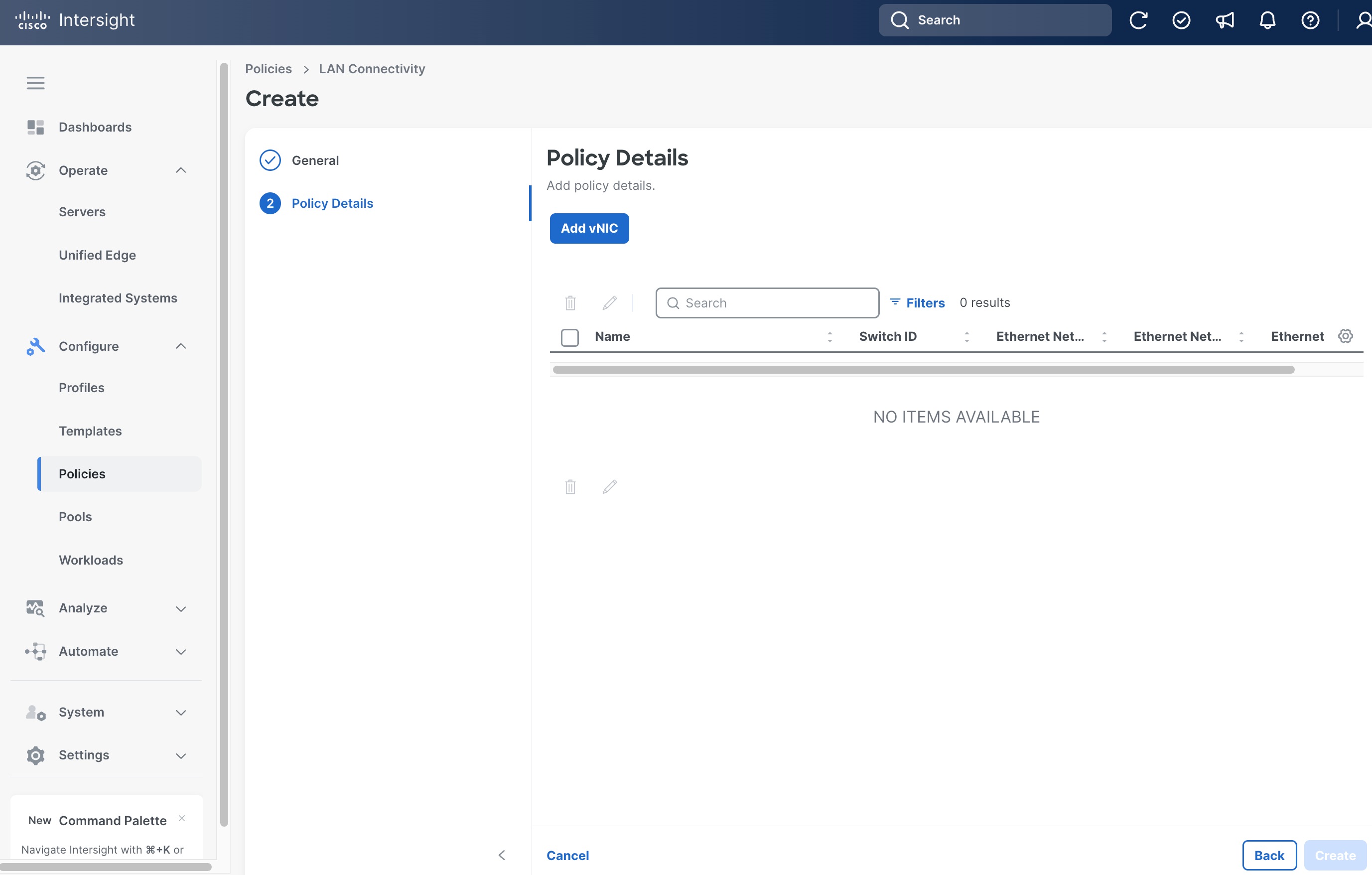
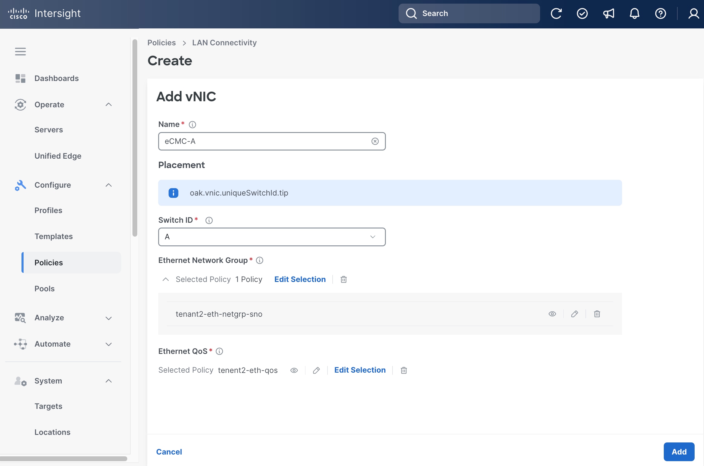
Step 10. On the Add vNIC page, provide the name, for example, eCMC-A.
Step 11. Select A as Switch ID.
Step 12. Select the Ethernet Network Group policy and Ethernet QoS policy we created in the previous steps, which are tenant2-eth-netgrp-sno and tenant2-eth-qos, respectively.
Step 13. Click Add.
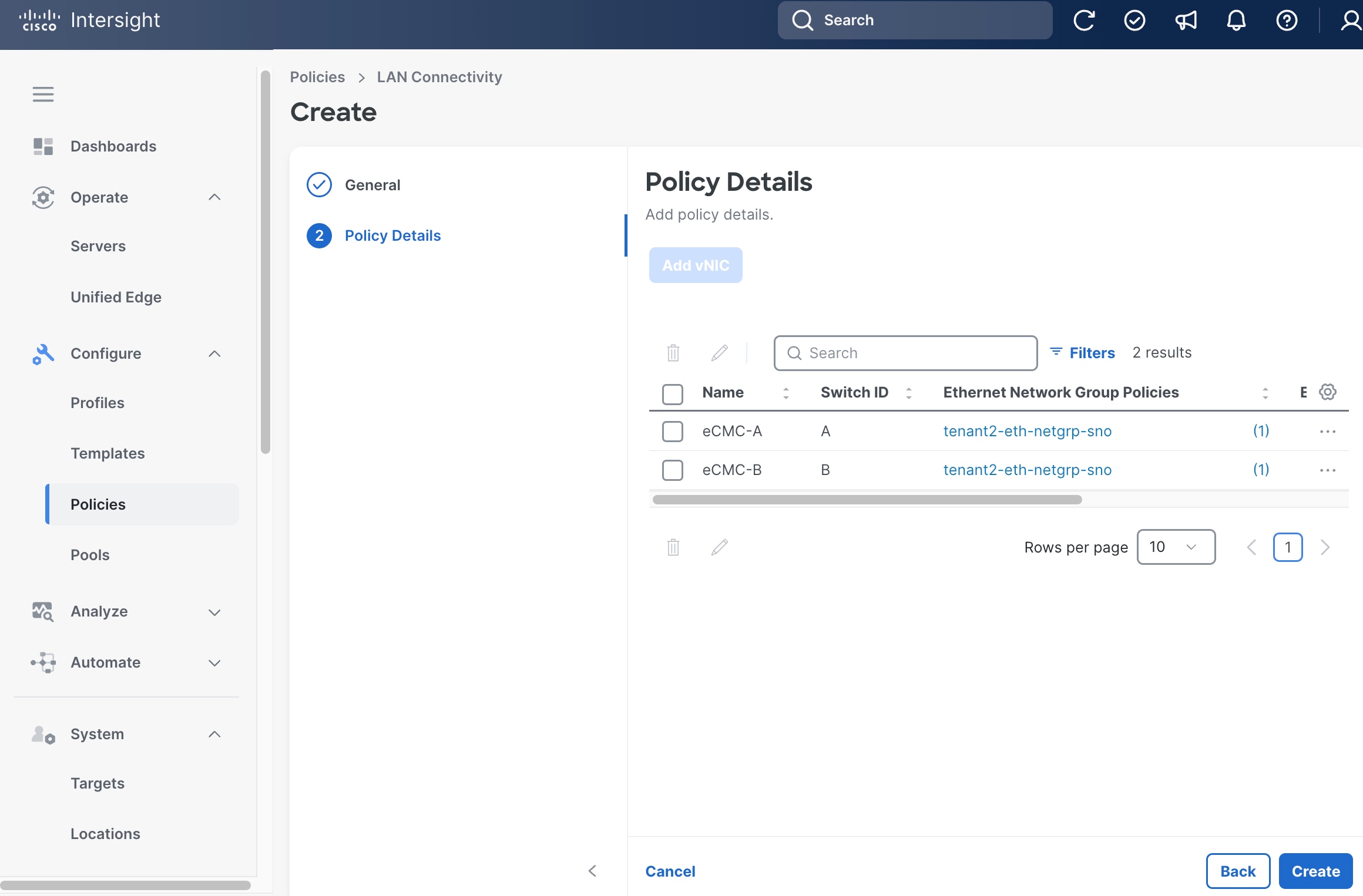
Step 14. From the Policy Details page, click Add vNIC.
Step 15. On the Add vNIC page again, provide a different name from the previous step, for example, eCMC-B.
Step 16. Select B as Switch ID.
Step 17. Select the Ethernet Network Group policy and Ethernet QoS policy we created in the previous steps, which are tenant2-eth-netgrp-sno and tenant2-eth-qos, respectively.
Step 18. Click Add.

Step 19. From the Policy Details page, click Create.
Procedure 13. Create Server Profile Templates
Step 1. Click Configure > Templates.
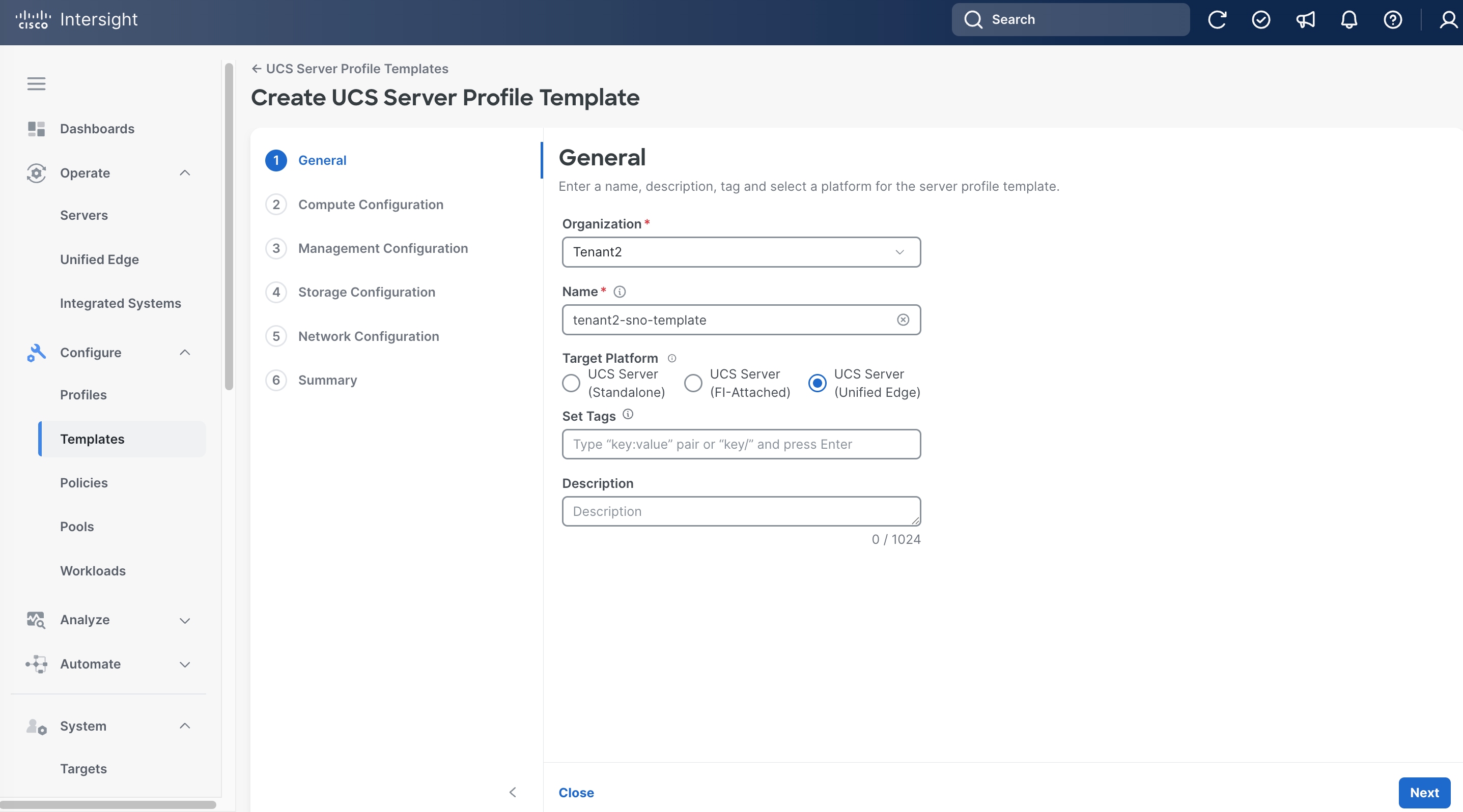
Step 2. On the Templates page, click UCS Server Profile Templates, then click Create UCS Server Profile Template.
Step 3. On the General page, select the correct Organization, for example, Tenant2.
Step 4. Provide a Name for the template, for example, tenant2-sno-template.
Step 5. Set UCS Server (Unified Edge) as the Target Platform
Step 6. (Optional) Provide Tags and Description.
Step 7. Click Next.
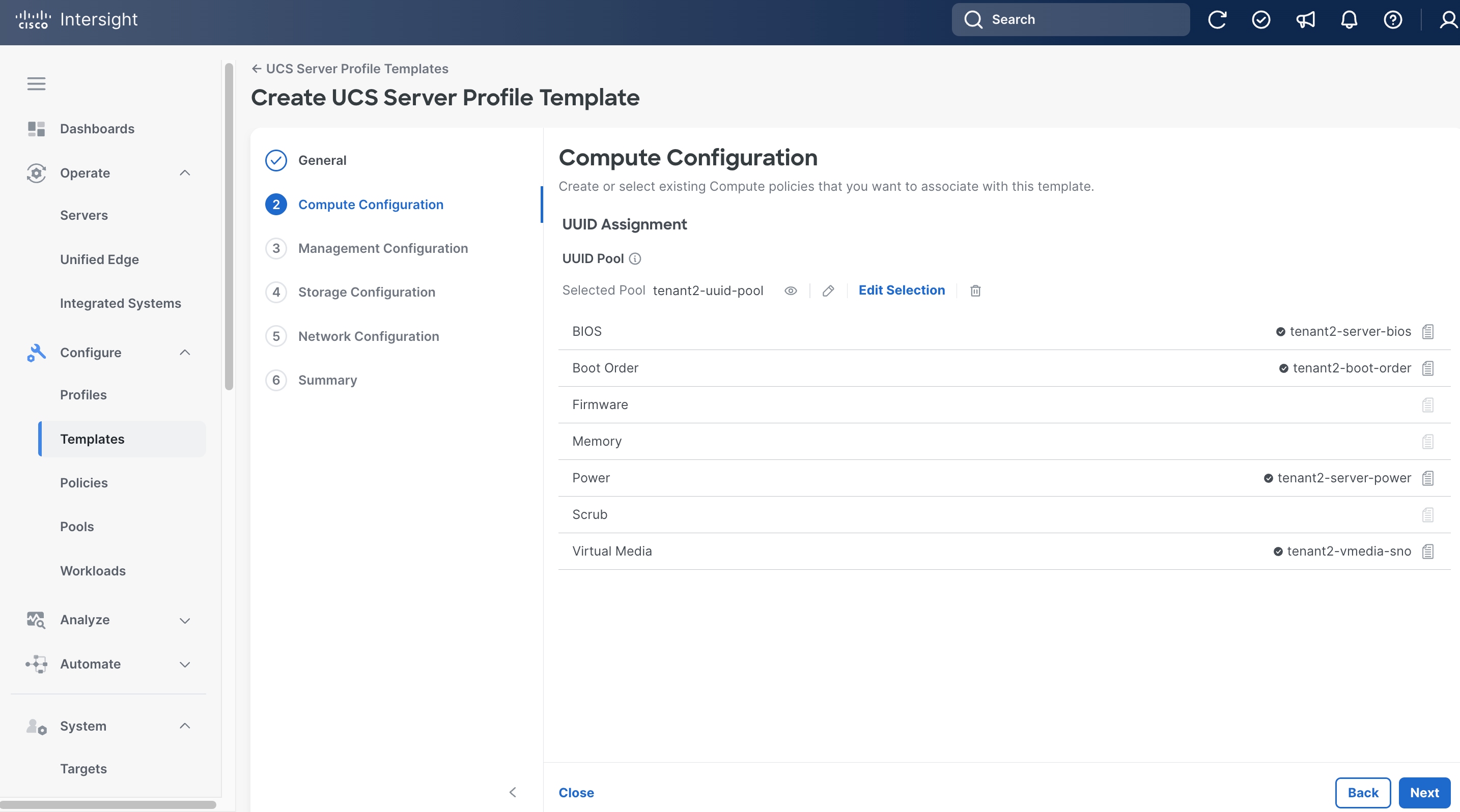
Step 8. On the Compute Configuration page, in UUID Pool section, click Select Pool, and choose the UUID pool created in the previous step, which is tenant2-uuid-pool.
Step 9. Click Select Policy next to BIOS. Select the BIOS policy created in the previous step, for example, tenant2-server-bios.
Step 10. Click Select Policy next to Boot Order. Select the Boot Order policy created in the previous step, for example, tenant2-boot-order.
Step 11. Click Select Policy next to Power. Select the Power policy created in the previous step, for example, tenant2-server-power.
Step 12. Click Select Policy next to Virtual Media. Select the Virtual Media policy created in the previous step, for example, tenant2-vmedia-sno.
Step 13. Click Next.
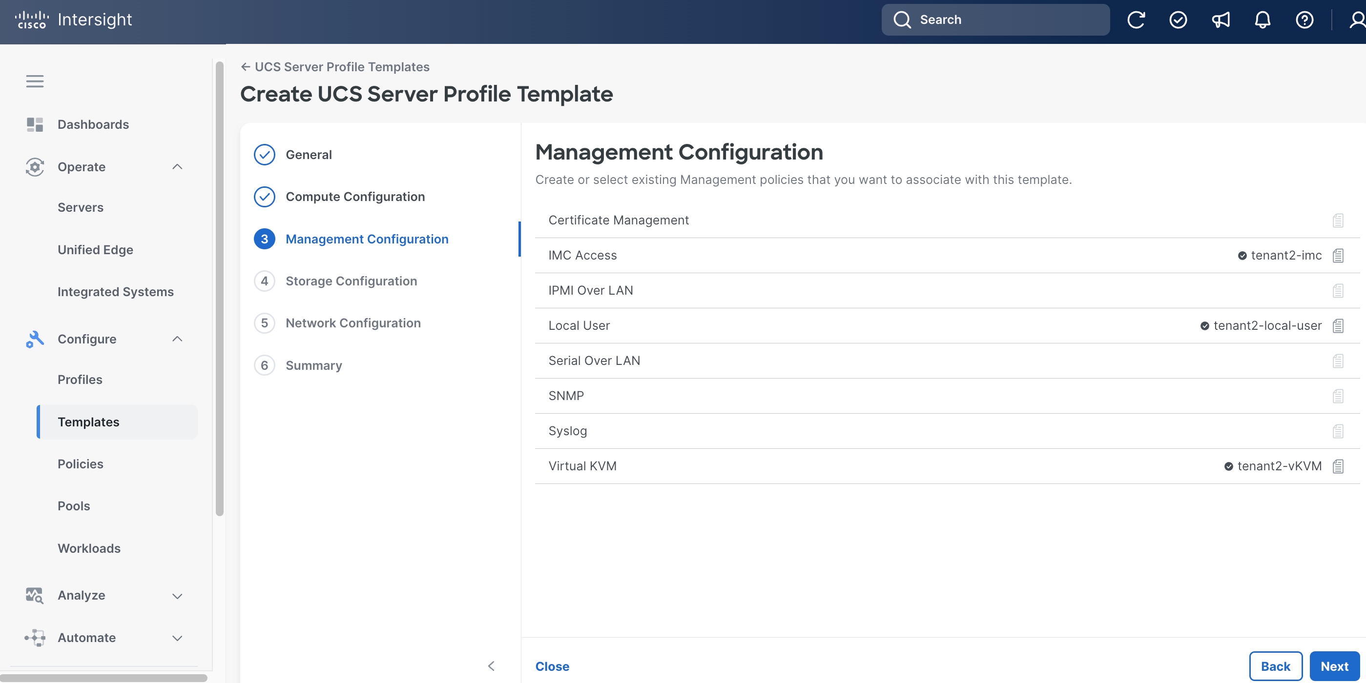
Step 14. On the Management Configuration page, click Select Policy next to IMC Access. Select IMC Access policy created in the previous step, for example, tenant2-imc.
Step 15. Click Select Policy next to Local User. Select the Local User policy created in the previous step, for example, tenant2-local-user.
Step 16. Click Select Policy next to Virtual KVM. Select the Virtual KVM policy created in the previous step, for example, tenant2-vKVM.
Step 17. Click Next.
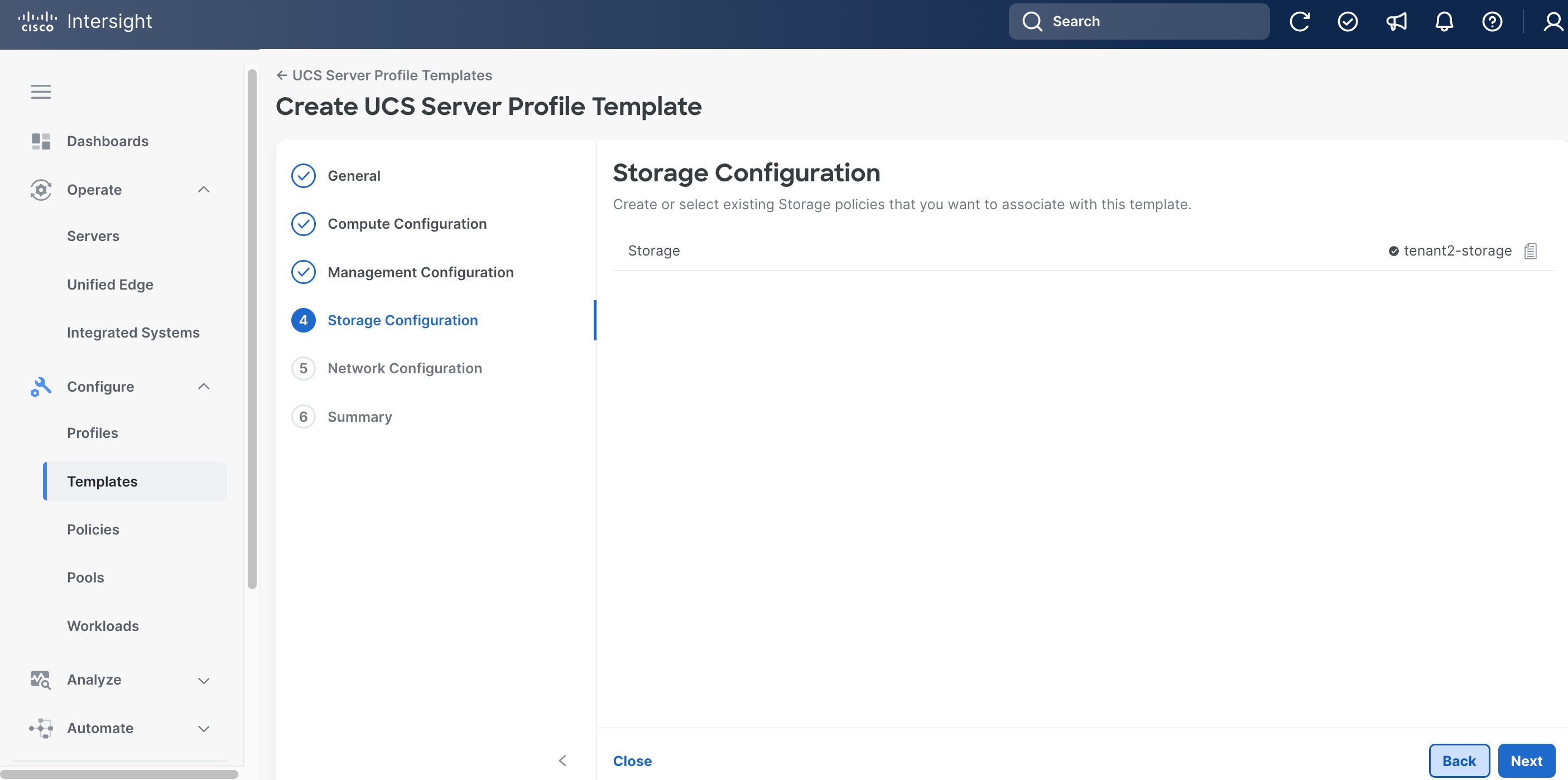
Step 18. On the Storage Configuration page, click Select Policy next to Storage. Select Storage policy created in the previous step, for example, tenant2-storage.
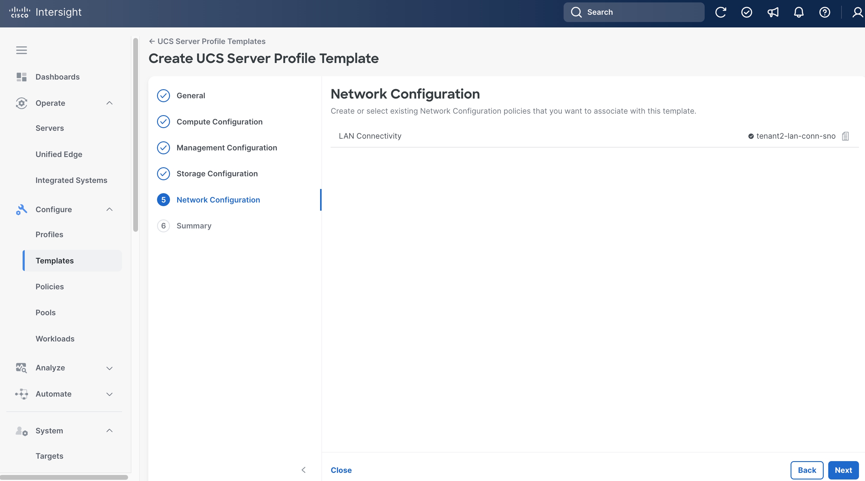
Step 19. On the Network Configuration page, click Select Policy next to LAN Connectivity. Select the LAN Connectivity policy created in the previous step, for example, tenant2-lan-conn-sno.
Step 20. On the Summary page, click Derive Profile.
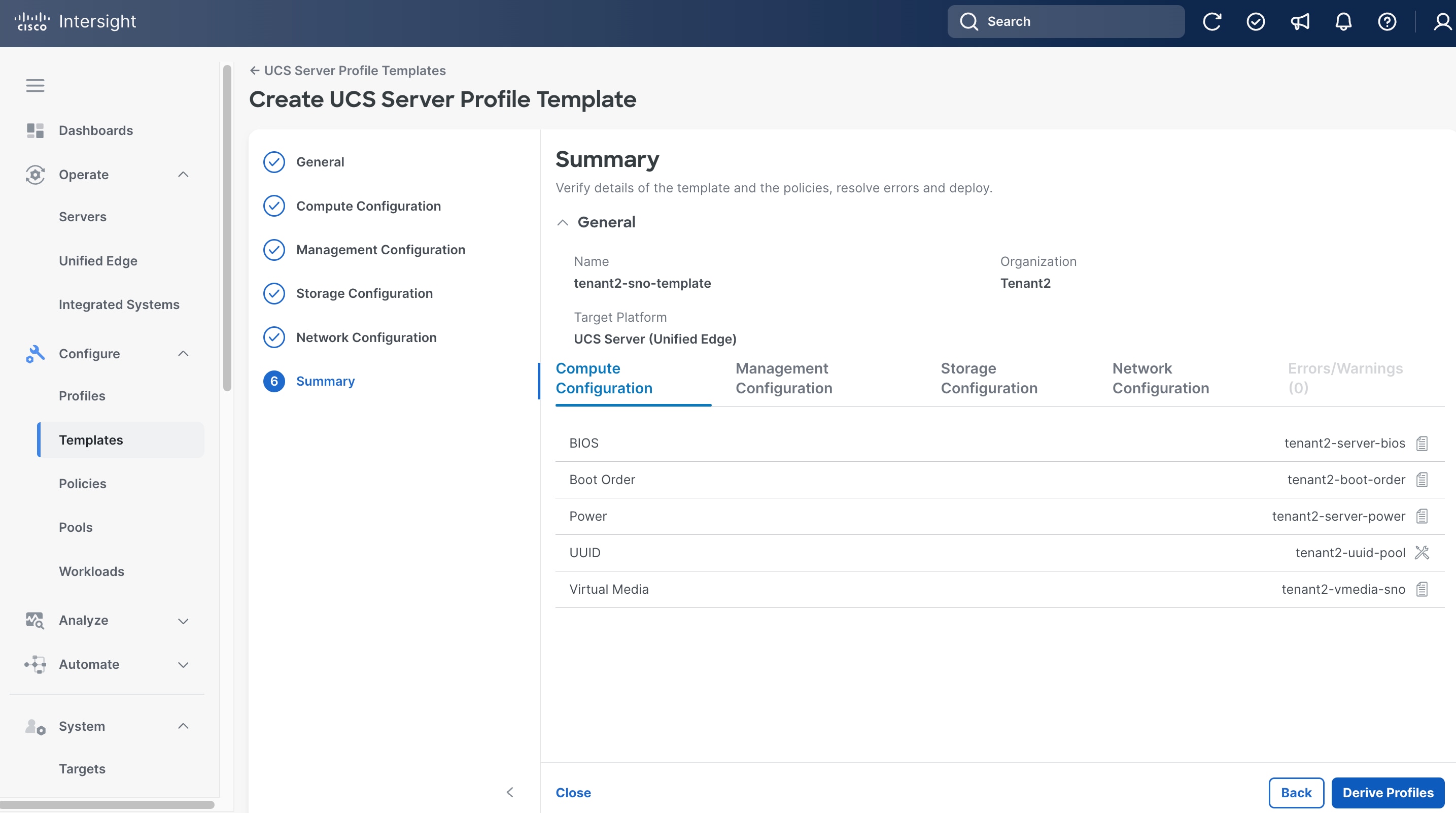
Provision Servers
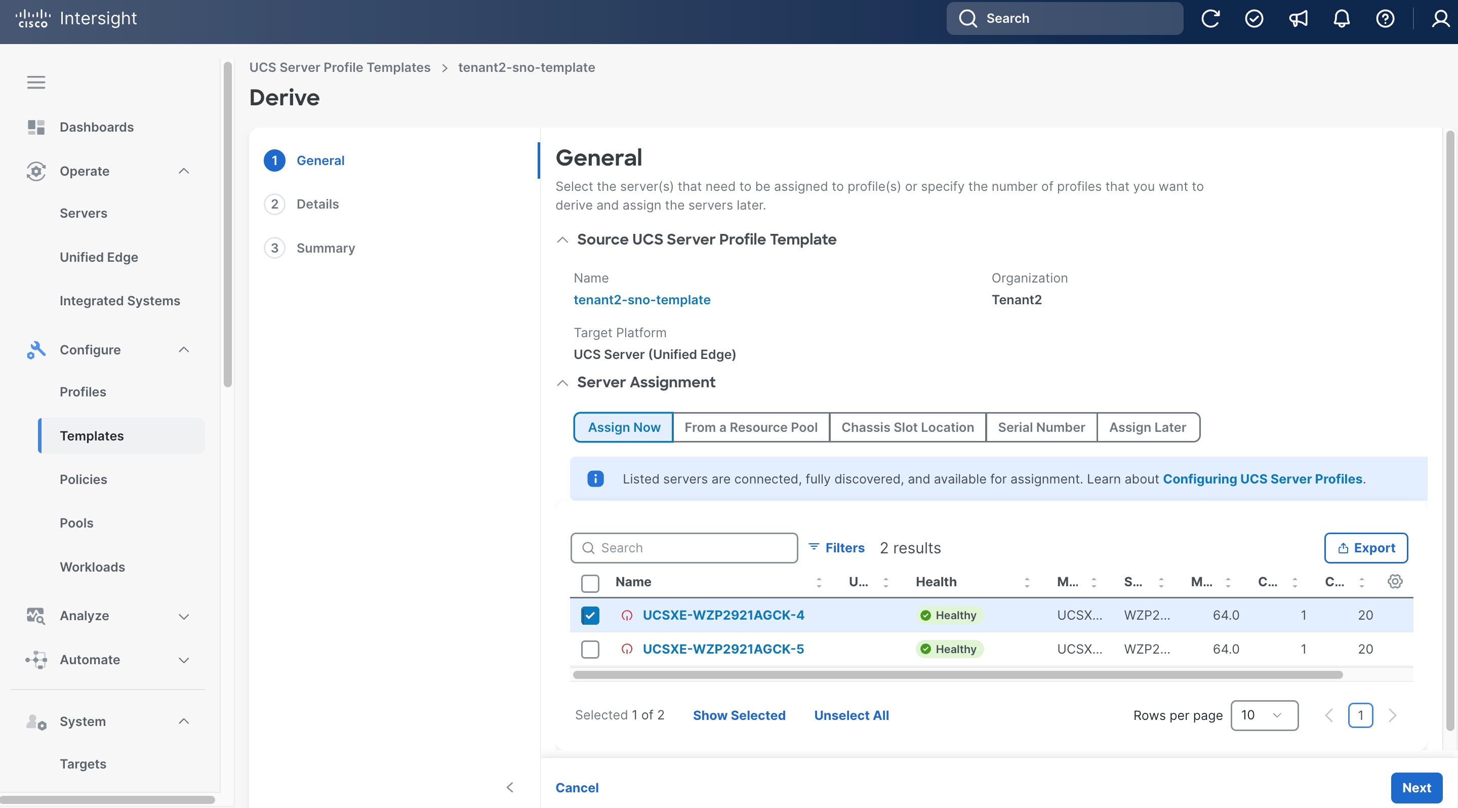
Procedure 14. Derive and Apply Server Profile
Step 1. On the General page, select the server you want to assign to the server profile.
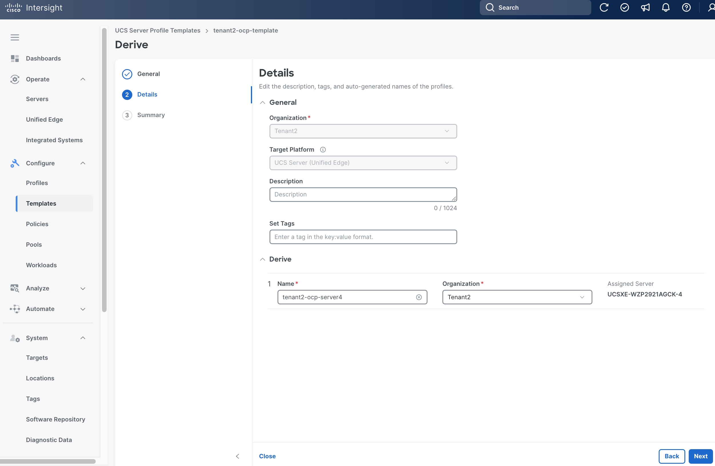
Step 2. Click Next.
Step 3. On the Details page, provide Name, for example, tenant2-sno-server4, and make sure the Organization is set to the right value, for example, Tenant2.
Step 4. (Optional) Provide Tags and Description.
Step 5. Click Next.
Step 6. On the Summary page, click Derive.
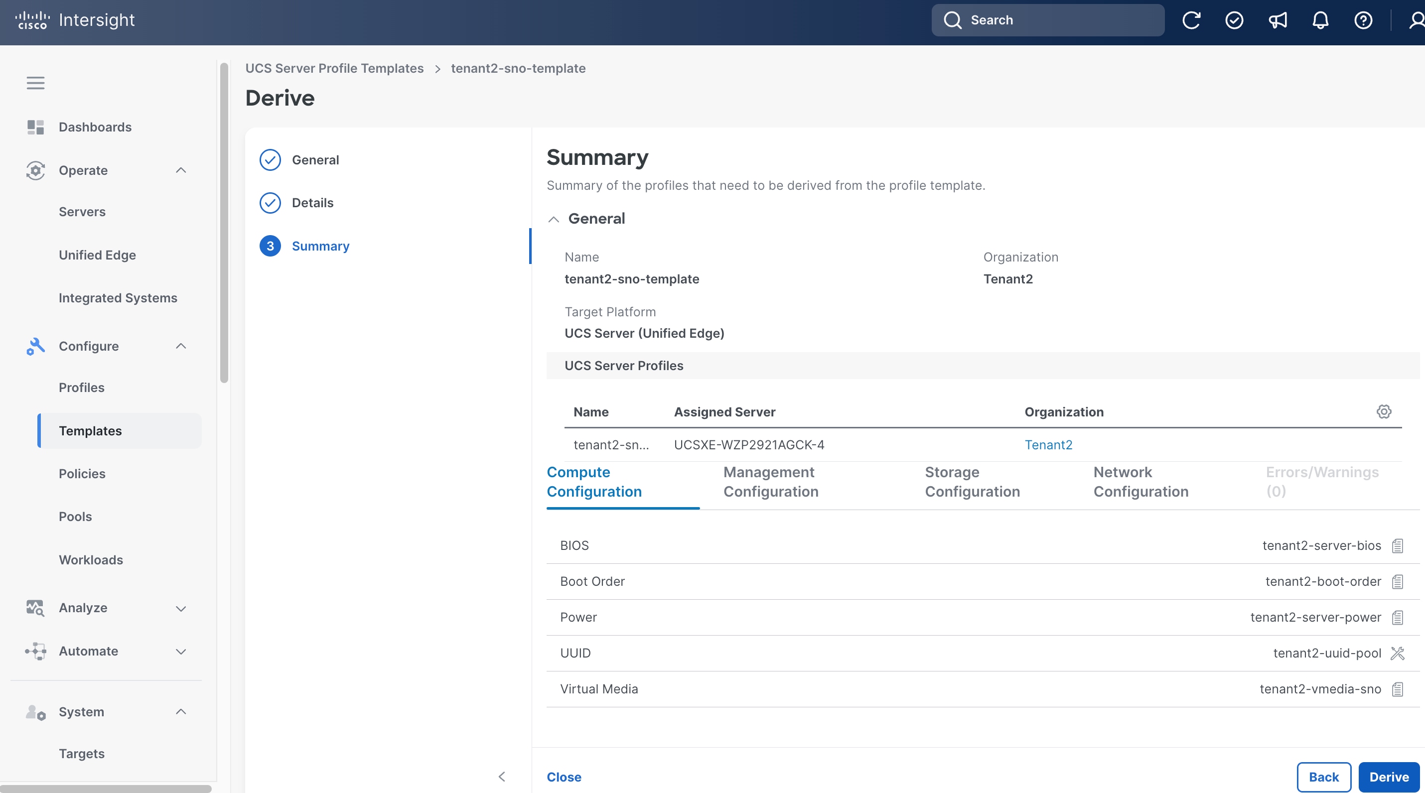
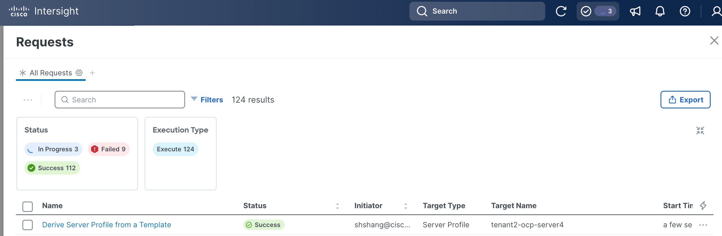
Step 7. Click the checkmark icon at the upper right corner to monitor the status of profile creation request. It will take a few minutes for the request Derive Server Profile from a Template to reach the Success status.
Procedure 15. Apply Server Profile
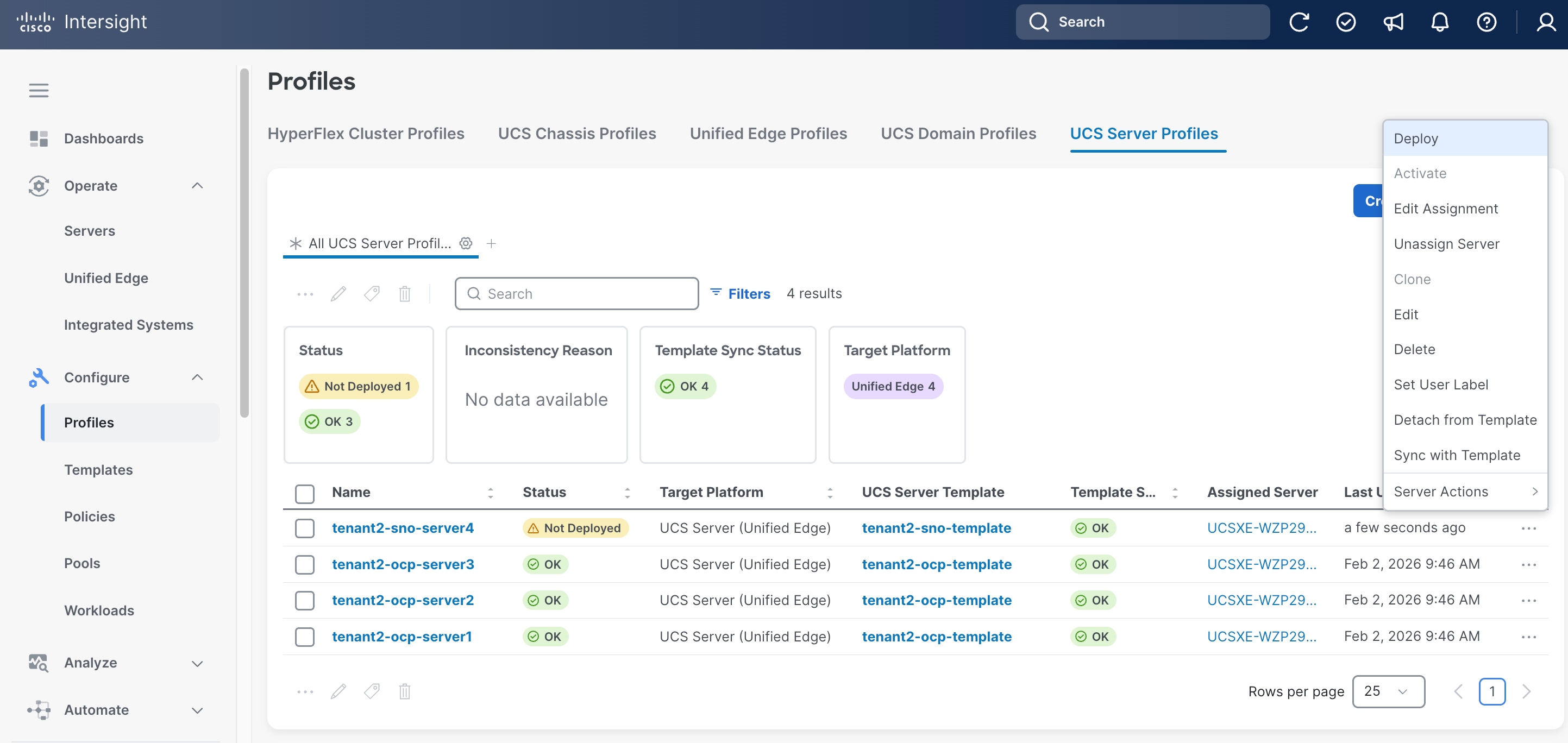
Step 1. Click Configure > Profiles.
Step 2. On the Profiles page, select the UCS Server Profiles.
Step 3. Select a profile created in the previous step. Click the ellipses (…) at the end of the row, then click Deploy from the drop-down list.
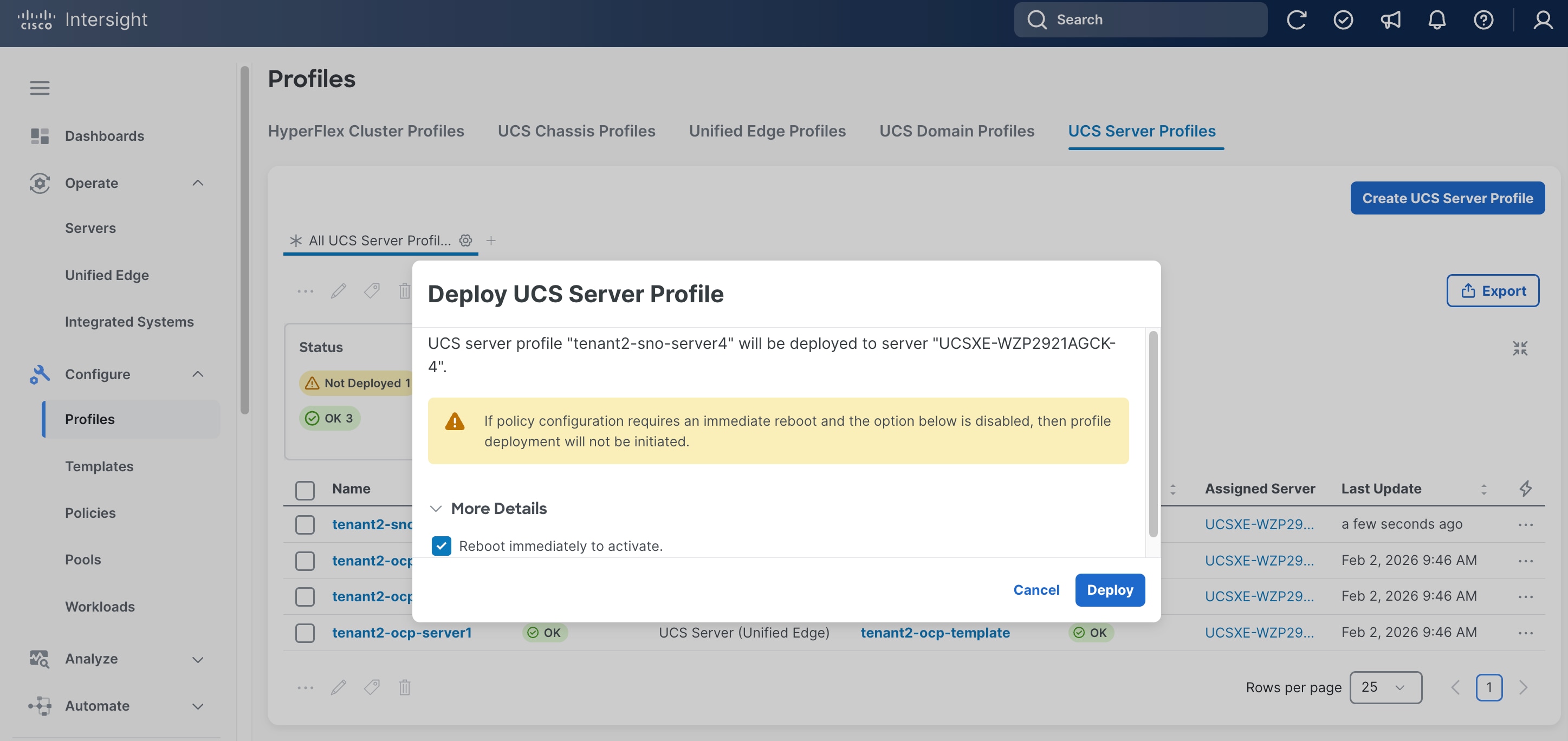
Step 4. In the pop-up window, click Reboot immediately to active, then click Deploy.
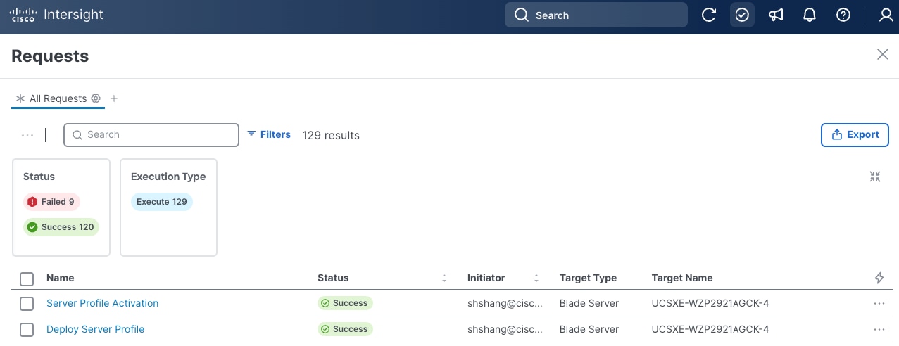
Step 5. Click the checkmark icon at the upper right corner to monitor the status of server profile deployment request. It will take a while for the requests Deploy Server Profile and Server Profile Activation to reach Success status.
Step 6. Go to Configure > Servers. Verify the Health status for the server is Healthy.
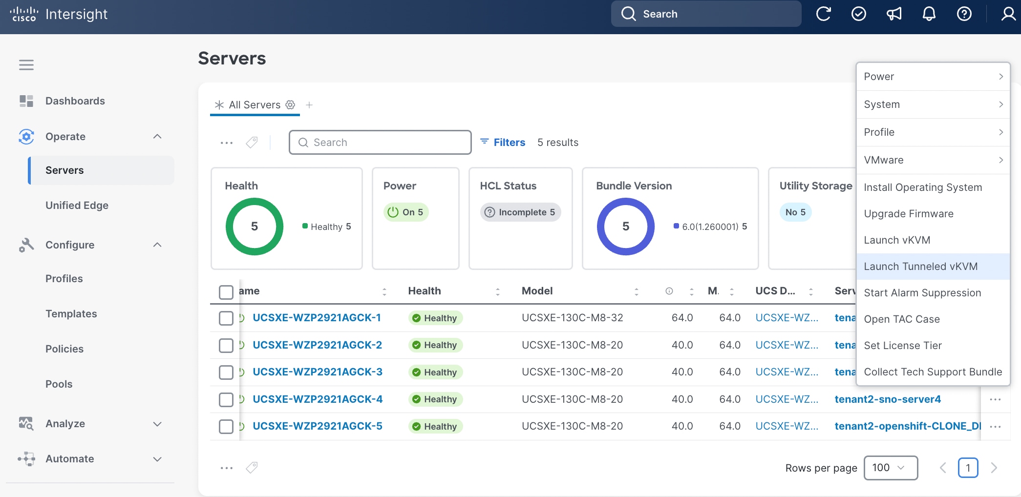
Procedure 16. Enable Tunnel vKVM (Optional)
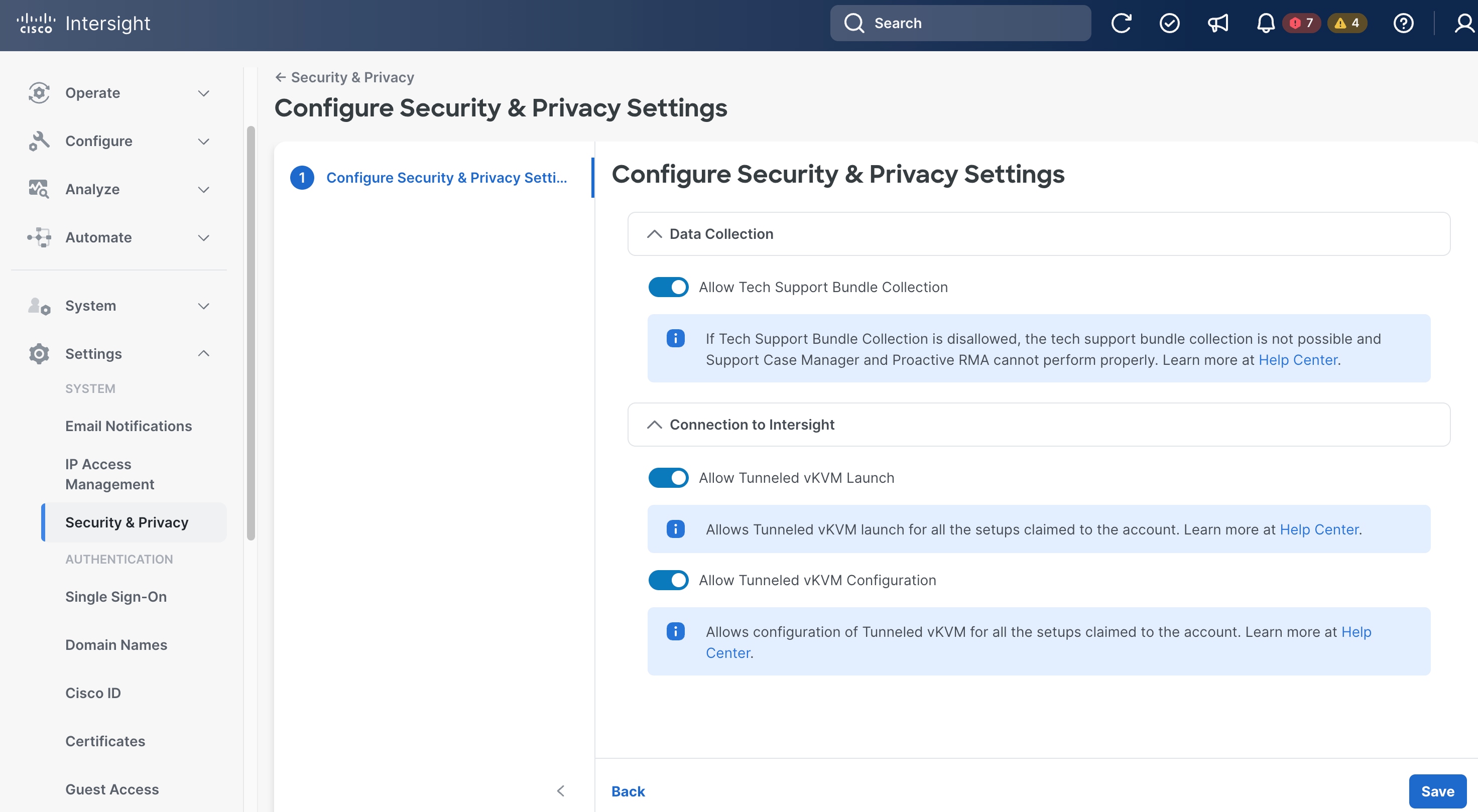
Step 1. Go to Settings > Security & Privacy, then click Configure.
Step 2. On the Configure Security & Privacy Settings page, in Connection to Intersight section, toggle the switch to enable Allow Tunneled vKVM Launch and Allow Tunneled vKVM Configuration.
Step 3. Click Save.
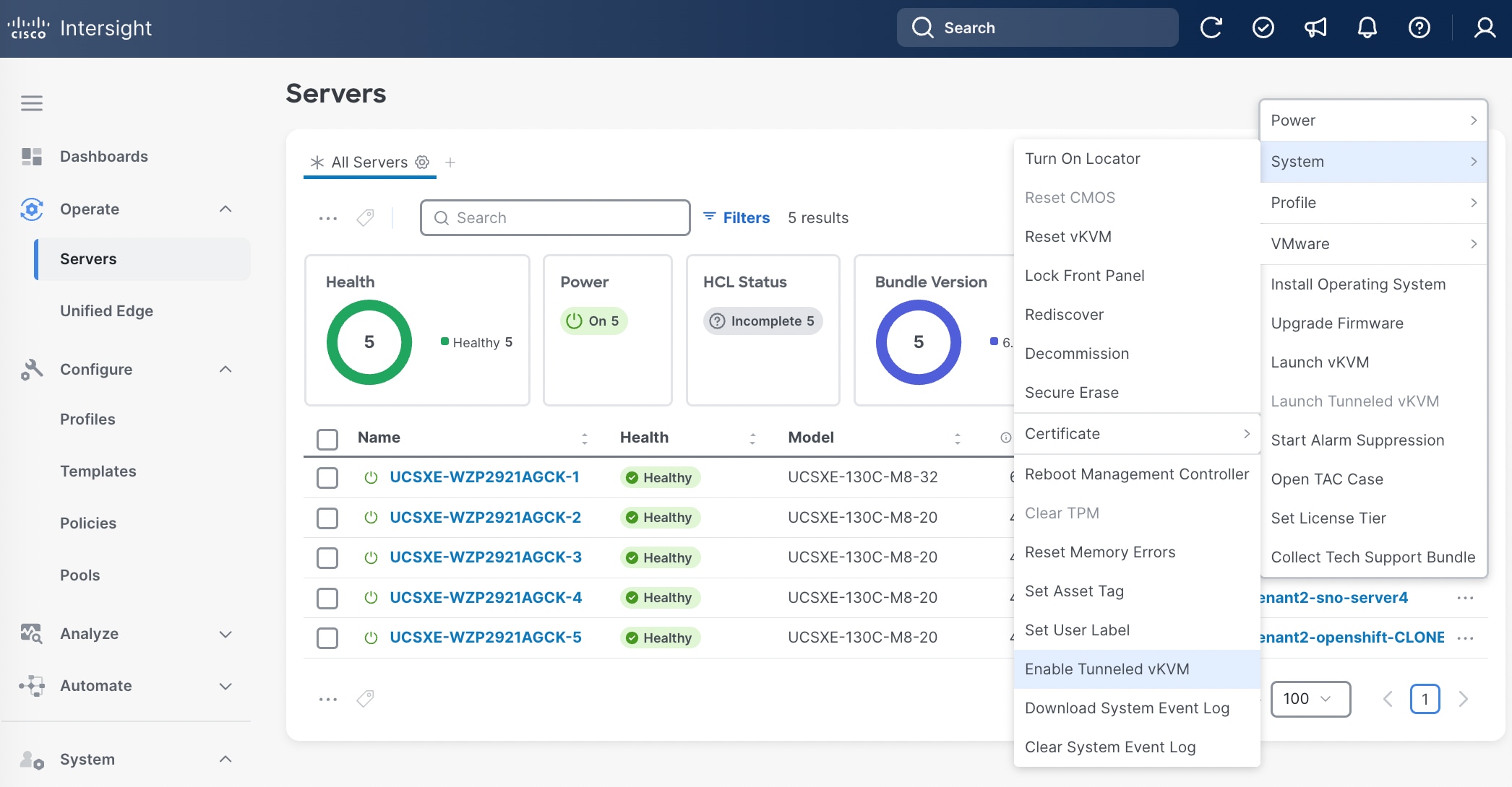
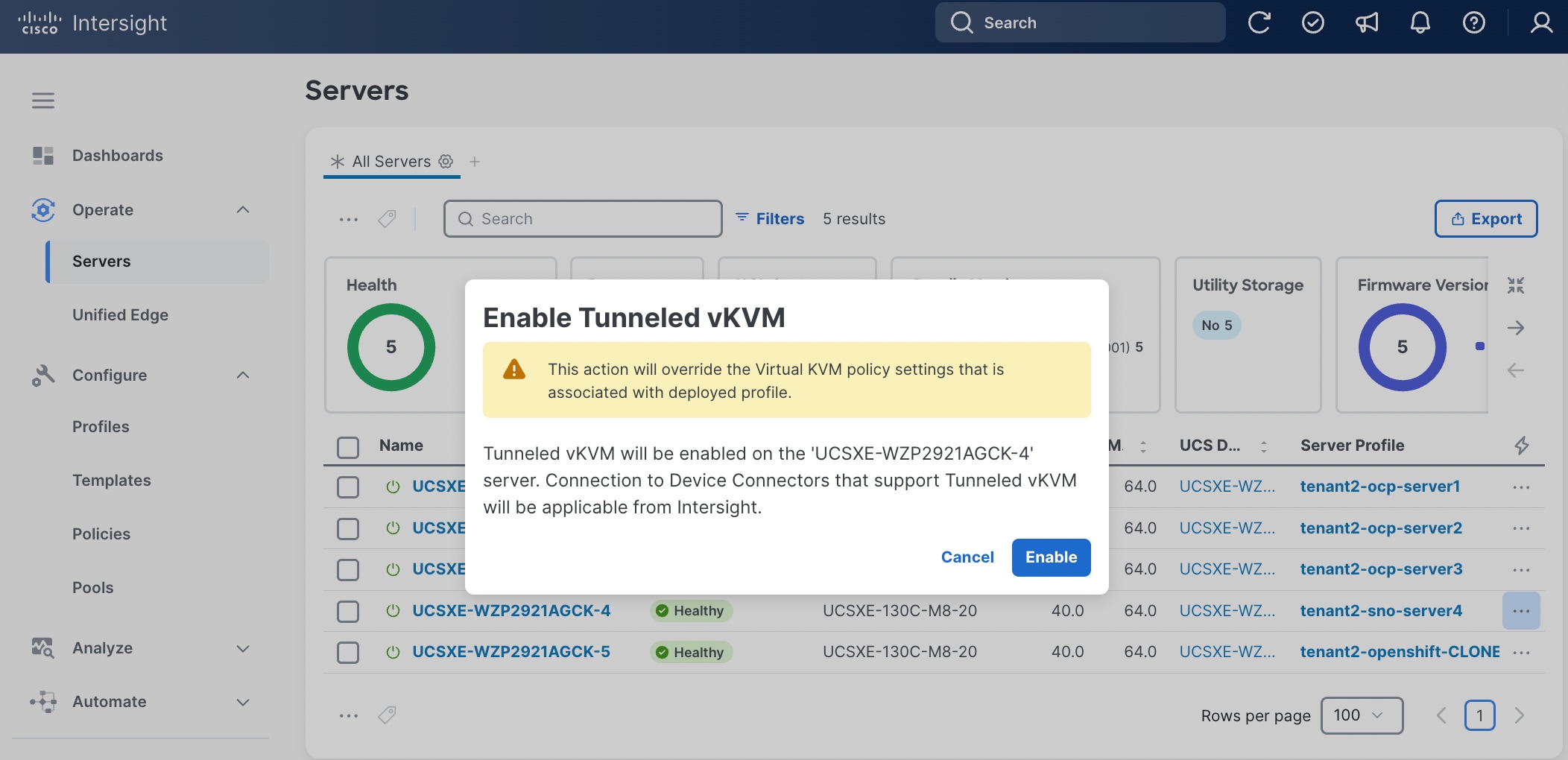
Step 4. Go to Operate > Servers, select the server and then click the ellipses (…) at the end of the row. From the drop-down list, select System > Enable Tunneled vKVM.
Step 5. In the pop-up window, click Enable.
Step 6. Go to Operate > Servers, select the server and then click the ellipses (…) at the end of the row. From the drop-down list, select Launch Tunneled vKVM.
Install and Configure SNO Using Assisted Installer
This section describes the deployment procedures for installing a Red Hat OpenShift Single Node (SNO) cluster using the Assisted Installer method. The Assisted Installer provides a web-based graphical user interface that simplifies the deployment process through guided workflows and automated validation checks. This approach is recommended for users who prefer an interactive installation experience with real-time feedback and minimal manual configuration.
Note: If you prefer a command-line interface (CLI) approach with direct YAML configuration management, go to Install and Configure SNO Using CLI and YAMLs, which provides detailed instructions for a declarative, automation-friendly deployment method.
The deployment process begins with the Assisted Installer to establish your OpenShift SNO first, then progressively builds the required infrastructure through operator installations. You'll configure networking capabilities through NMState, establish persistent storage with LVM, and enable virtualization features through the OpenShift Virtualization Operator. Optional VM secondary networks can be configured to support complex networking topologies. For environments with NVIDIA L4 GPU hardware, the guide includes additional configuration steps using the Node Feature Discovery and NVIDIA GPU Operators to unlock GPU-accelerated computing capabilities for your virtual machines.
Installation Flow:
● Deploy base OpenShift cluster via Assisted Installer
● Enable infrastructure operators: NMState, LVM Storage, OpenShift Virtualization
● Configure optional VM secondary networks (if required)
● Enable GPU support: Node Feature Discovery Operator + NVIDIA GPU Operator (L4 GPU systems)
Prerequisites
DNS Entries
The following domain and OpenShift cluster names are used in this deployment guide:
● Base Domain: tenant2.avatar.local
● OpenShift Cluster Name: sno
The DNS domain name for the OpenShift cluster should be the cluster name followed by the base domain, for example, sno.tenant2.avatar.local.
Prior to initiating the OpenShift installation see Table 5 for the DNS entries that must be configured on your DNS server.
Table 5. DNS FQDN Names Used in OCP SNO Cluster
| DNS Name |
IP Address |
Note |
| api.sno.tenant2.avatar.local |
10.131.7.104 |
Points to the API server endpoint IP address, used for cluster management and API access |
| *.apps.sno.tenant2.avatar.local |
10.131.7.104 |
Wildcard entry pointing to the Ingress/Router IP address, enabling access to all applications and routes deployed on the cluster |
| node.sno.tenant2.avatar.local |
10.131.7.104 |
Points to the node IP address(es) for Single Node OpenShift (SNO) deployment |
Reverse DNS entries for all IP addresses used by the cluster nodes, API endpoints, and ingress controllers must also be configured to map back to their respective hostnames. This ensures proper hostname resolution during installation and is required for various OpenShift components to function correctly.
SSH Key
Before proceeding with the OpenShift installation using the Assisted Installer, you must generate an SSH key pair on your local machine or workstation. The SSH key pair consists of a private key (which you retain securely) and a public key (which will be provided to the Assisted Installer during the cluster configuration process). The public key is embedded into all OpenShift nodes during installation, enabling secure SSH access to the cluster nodes for troubleshooting, maintenance, and administrative tasks.
OC CLI
Note: Follow the instruction in Red Hat documentation to install oc cli tool on the workstation: https://docs.redhat.com/en/documentation/openshift_container_platform/4.19/html/cli_tools/openshift-cli-oc
Procedure 1. Obtain MAC addresses
Obtain the MAC addresses of the two interfaces from the UCS Server Profile for the OpenShift node. The MAC addresses will be used in the static IP address binding to assign reserved IP addresses to the node.
Step 1. Log into Cisco Intersight
Step 2. Go to Operate > Servers, click the server you want to install OpenShift.
Step 3. Click the Inventory tab, go to Network Adapters > Adapter LOM-NIC-1, then click the Interfaces tab.

Step 4. Write down the MAC addresses for network interface 1, which is associated with chassis-1/switch-WZP29259V1L/slot-1/muxhostport-6, and network interface 2, which is associated with chassis-1/switch-WZP29259V2C/slot-1/muxhostport-6. These values will be used to create static IP assignment:
● Network Interface 1 MAC =
● Network Interface 2 MAC =
Note: The chassis and switch identifiers shown in the interface associations (e.g., chassis-1/switch-WZP29259V1L/slot-1/muxhostport-6) are examples from this deployment and will differ in your environment.
Procedure 2. Install Red Hat OpenShift Using Assisted Installer
Step 1. Launch web browser and connect to Red Hat Hybrid Cloud Console here: https://console.redhat.com/ and log into your Red Hat account.
Step 2. Click OpenShift in Red Hat OpenShift block.
Step 3. On the Featured OpenShift cluster types page, click Create cluster in Red Hat OpenShift Container Platform.
Step 4. On the Cluster Type page, select the Datacenter tab and then select Bare Metal (x86_64).
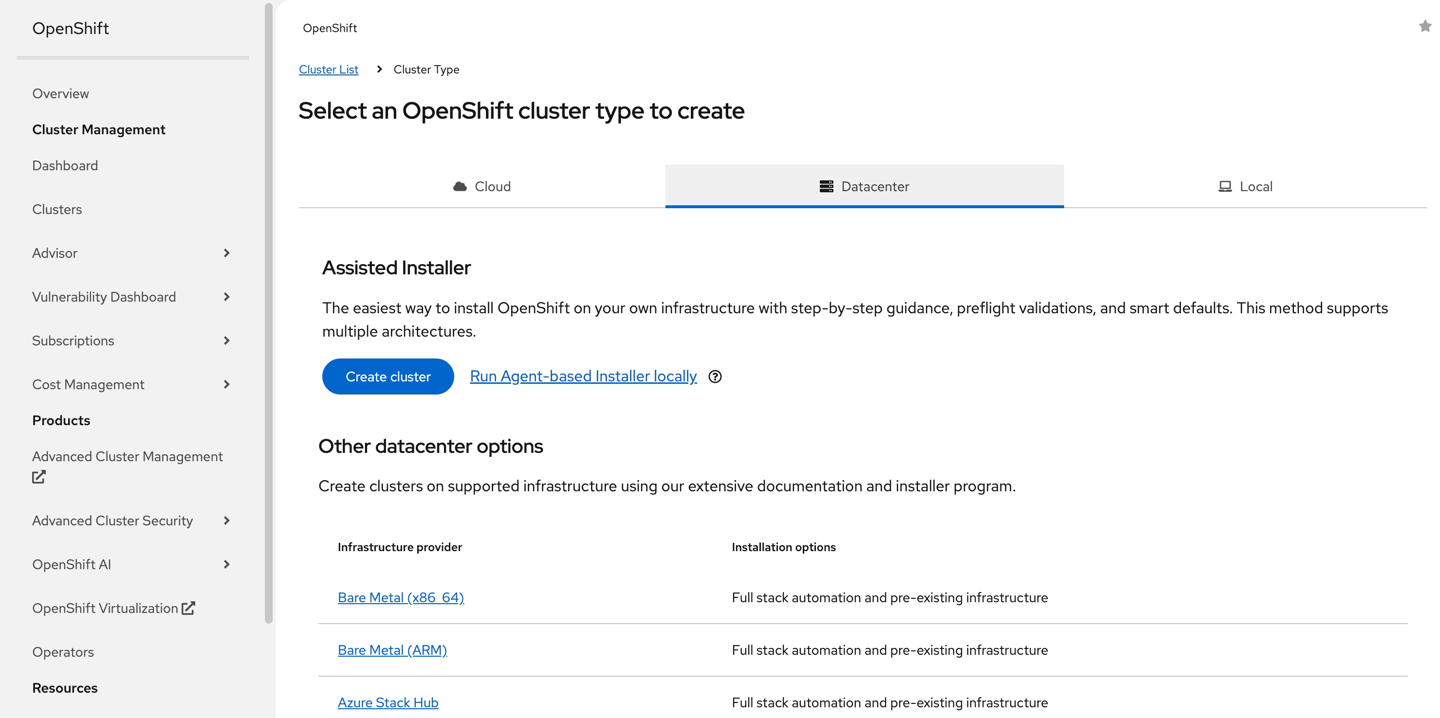
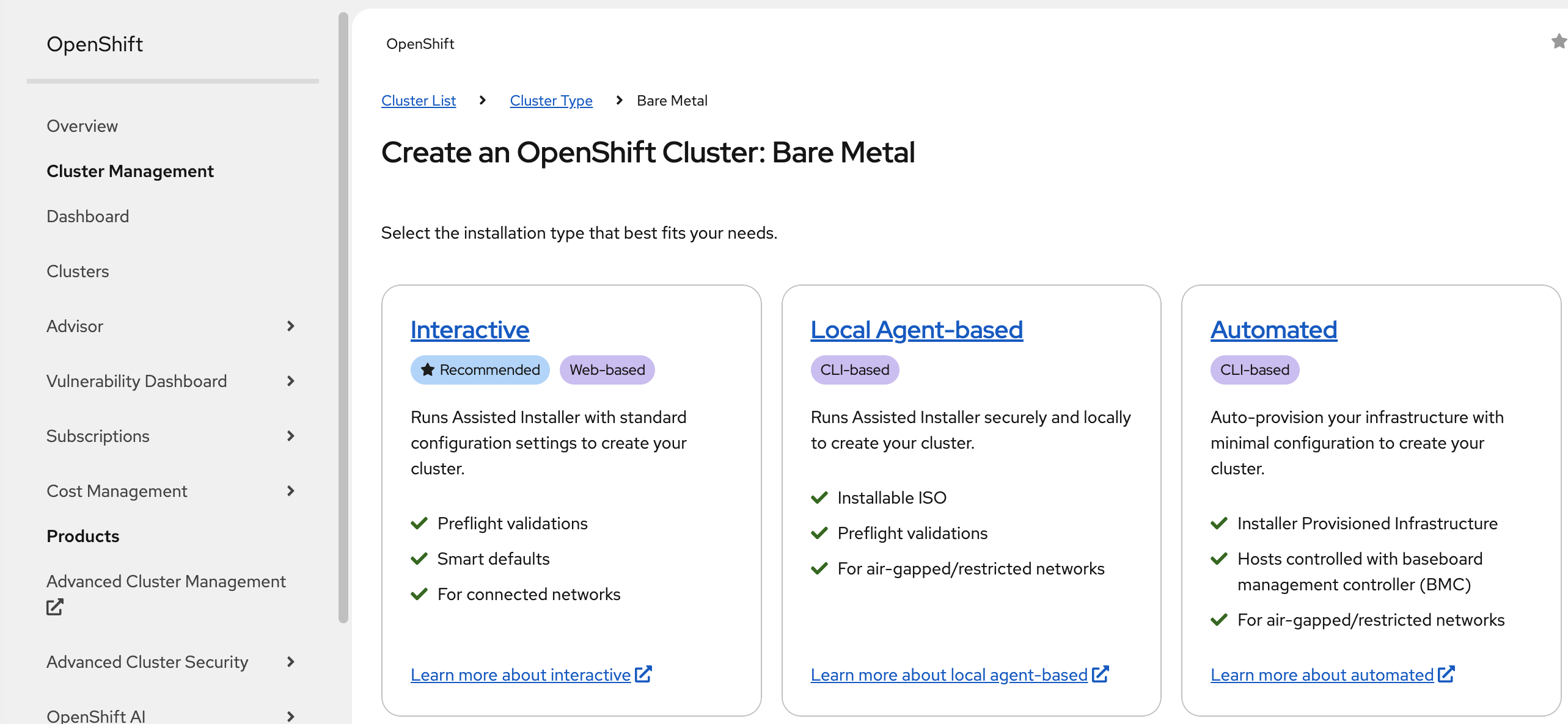
Step 5. Select Interactive to launch the Assisted Installer.
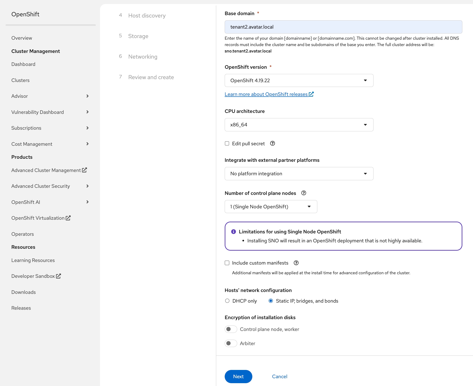
Step 6. On the Cluster details page, provide the Cluster name and Base domain.
Step 7. Select the OpenShift 4.19.22 version.
Step 8. In the Number of control plane nodes drop-down list, select 1(Single Node OpenShift).
Step 9. In the Hosts’ network configuration section, select Static IP, bridges, and bonds.
Step 10. Scroll down and click Next.
Step 11. On the Static network configurations page, choose YAML view, then click Start from scratch in the Host 1 section.
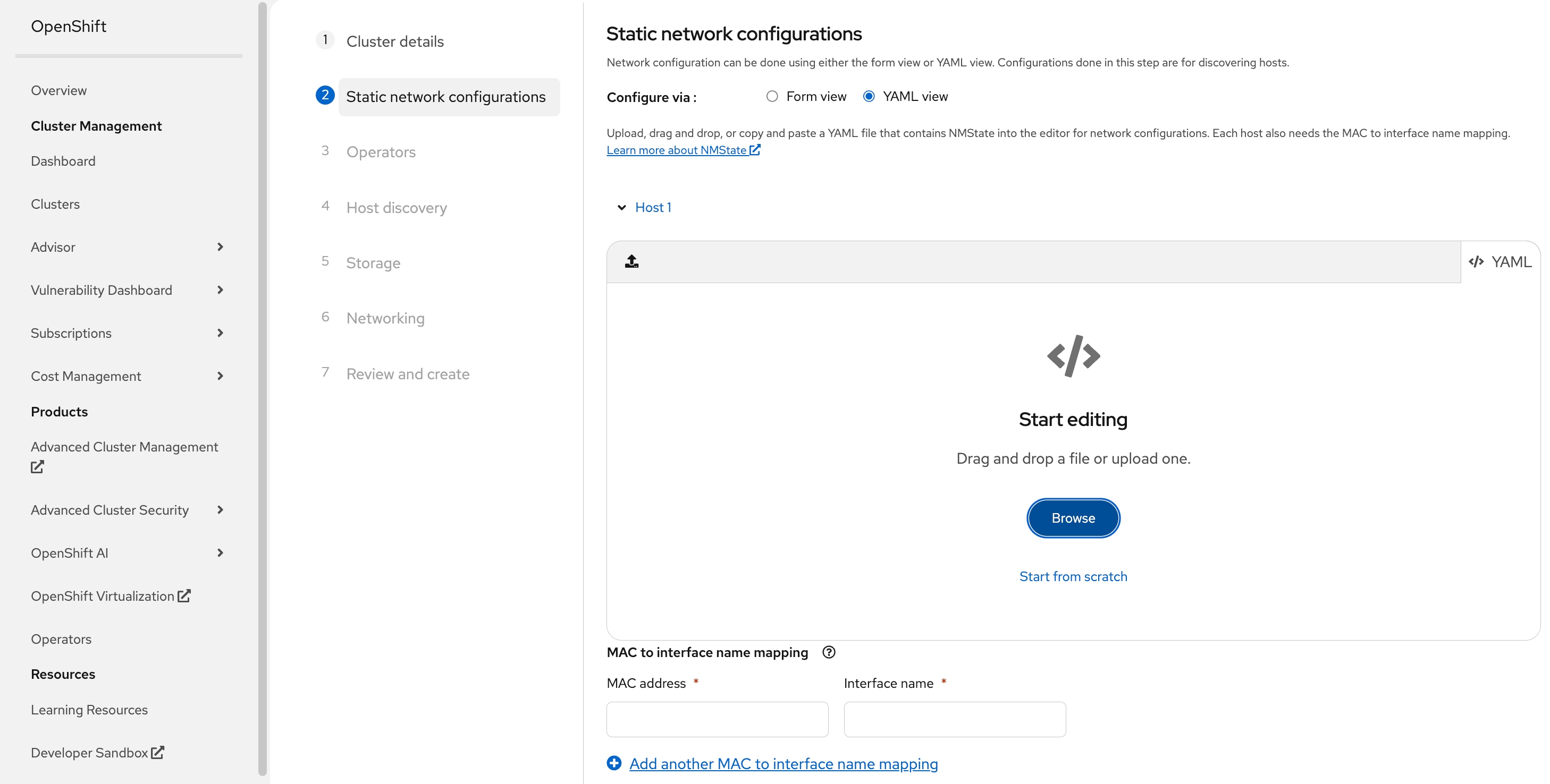
Step 12. Create a YAML based on the following template. Copy and paste the yaml to the Assisted Installer window.
Before creating the YAML configuration, gather the following information:
●
●
●
●
●
interfaces:
- name: eno1
type: ethernet
state: up
mtu: 9000
mac-address: <NODE-NIC1-MAC>
ipv4:
enabled: false
- name: eno2
type: ethernet
state: up
mtu: 9000
mac-address: <NODE-NIC2-MAC>
ipv4:
enabled: false
- name: bond0
type: bond
state: up
mtu: 9000
link-aggregation:
mode: active-backup
options:
primary: eno1
miimon: "100"
primary_reselect: always
port:
- eno1
- eno2
ipv4:
enabled: false
ipv6:
enabled: false
- name: bond0.<ACCESS-VLAN-ID>
type: vlan
state: up
mtu: 1500
vlan:
base-iface: bond0
id: <ACCESS-VLAN-ID>
ipv4:
address:
- ip: <NODE-IP>
prefix-length: <NODE-SUBNET-MASK-LENGTH>
dhcp: false
enabled: true
ipv6:
enabled: false
routes:
config:
- destination: 0.0.0.0/0
next-hop-address: <ACCESS-NETWORK-DEFAULT-GATEWAY>
next-hop-interface: bond0.<ACCESS-VLAN-ID>
table-id: 254
dns-resolver:
config:
server:
- <DNS-SERVER-IP>
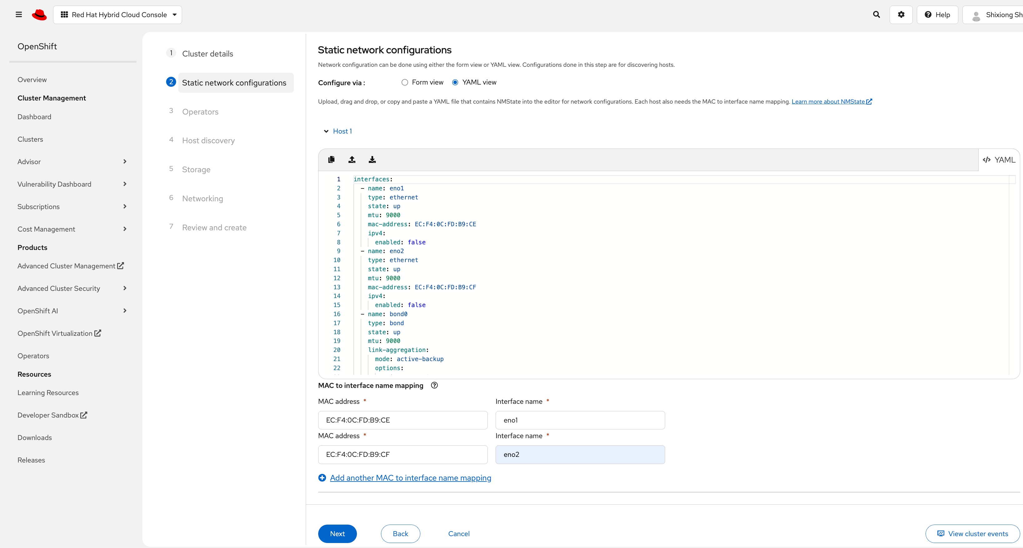
Here is the example:
interfaces:
- name: eno1
type: ethernet
state: up
mtu: 9000
mac-address: EC:F4:0C:FD:B9:CE
ipv4:
enabled: false
- name: eno2
type: ethernet
state: up
mtu: 9000
mac-address: EC:F4:0C:FD:B9:CF
ipv4:
enabled: false
- name: bond0
type: bond
state: up
mtu: 9000
link-aggregation:
mode: active-backup
options:
primary: eno1
miimon: "100"
primary_reselect: always
port:
- eno1
- eno2
ipv4:
enabled: false
ipv6:
enabled: false
- name: bond0.1317
type: vlan
state: up
mtu: 1500
vlan:
base-iface: bond0
id: 1317
ipv4:
address:
- ip: 10.131.7.104
prefix-length: 24
dhcp: false
enabled: true
ipv6:
enabled: false
routes:
config:
- destination: 0.0.0.0/0
next-hop-address: 10.131.7.1
next-hop-interface: bond0.1317
table-id: 254
dns-resolver:
config:
server:
- 10.140.1.101
Step 13. On the Static network configuration page, in MAC to interface name mapping section, use eno1 as the interface name associated with <NODE-NIC1-MAC>, and use eno2 as the interface name associated with <NODE-NIC2-MAC>.
Step 14. Click Next.
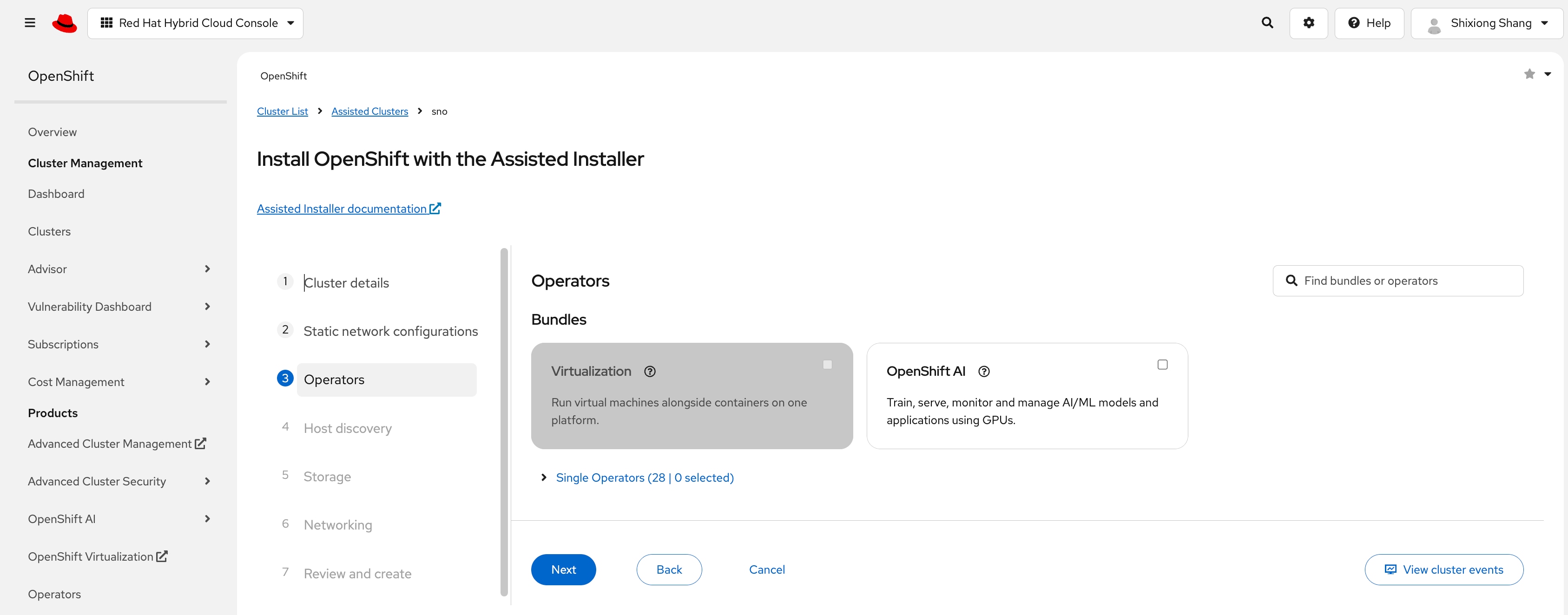
Step 15. On the Operators page, click Next.
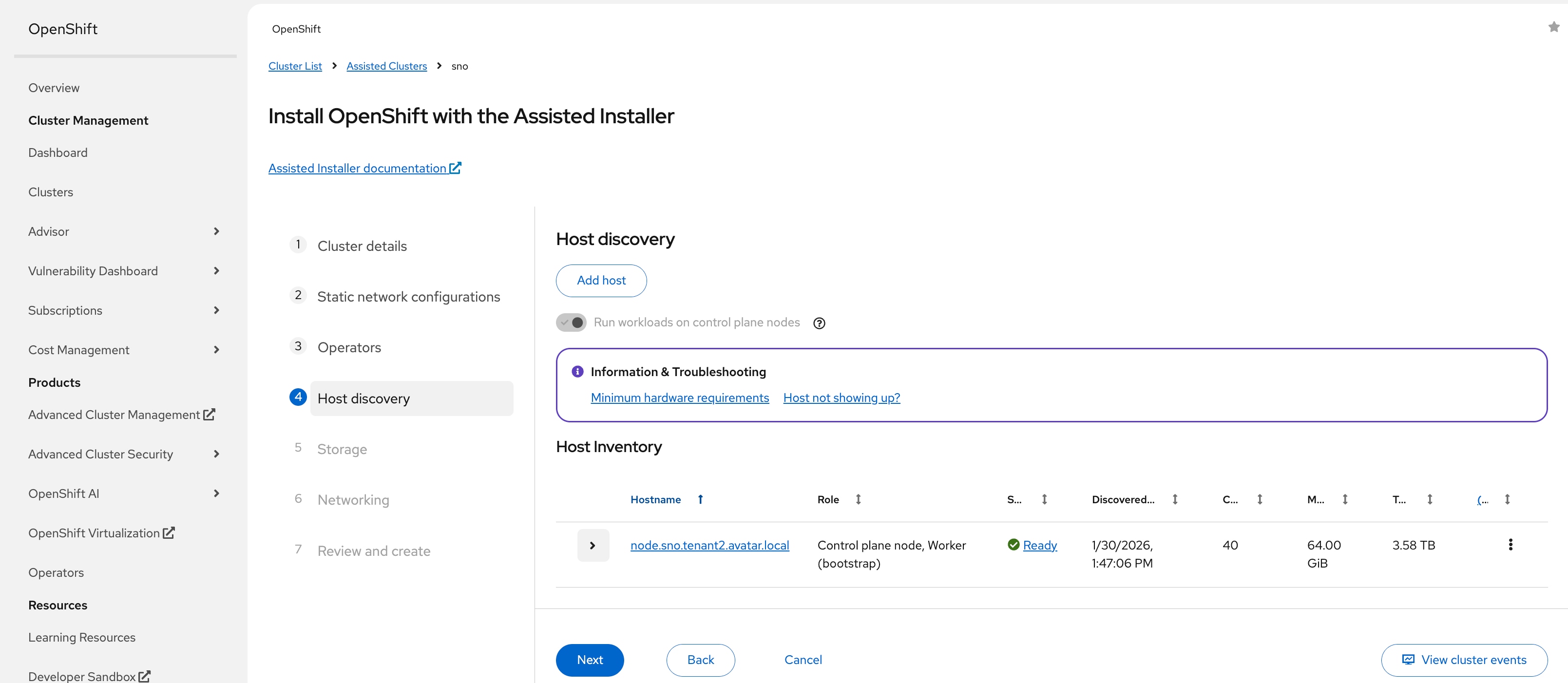
Step 16. On the Host discovery page, click Add host.
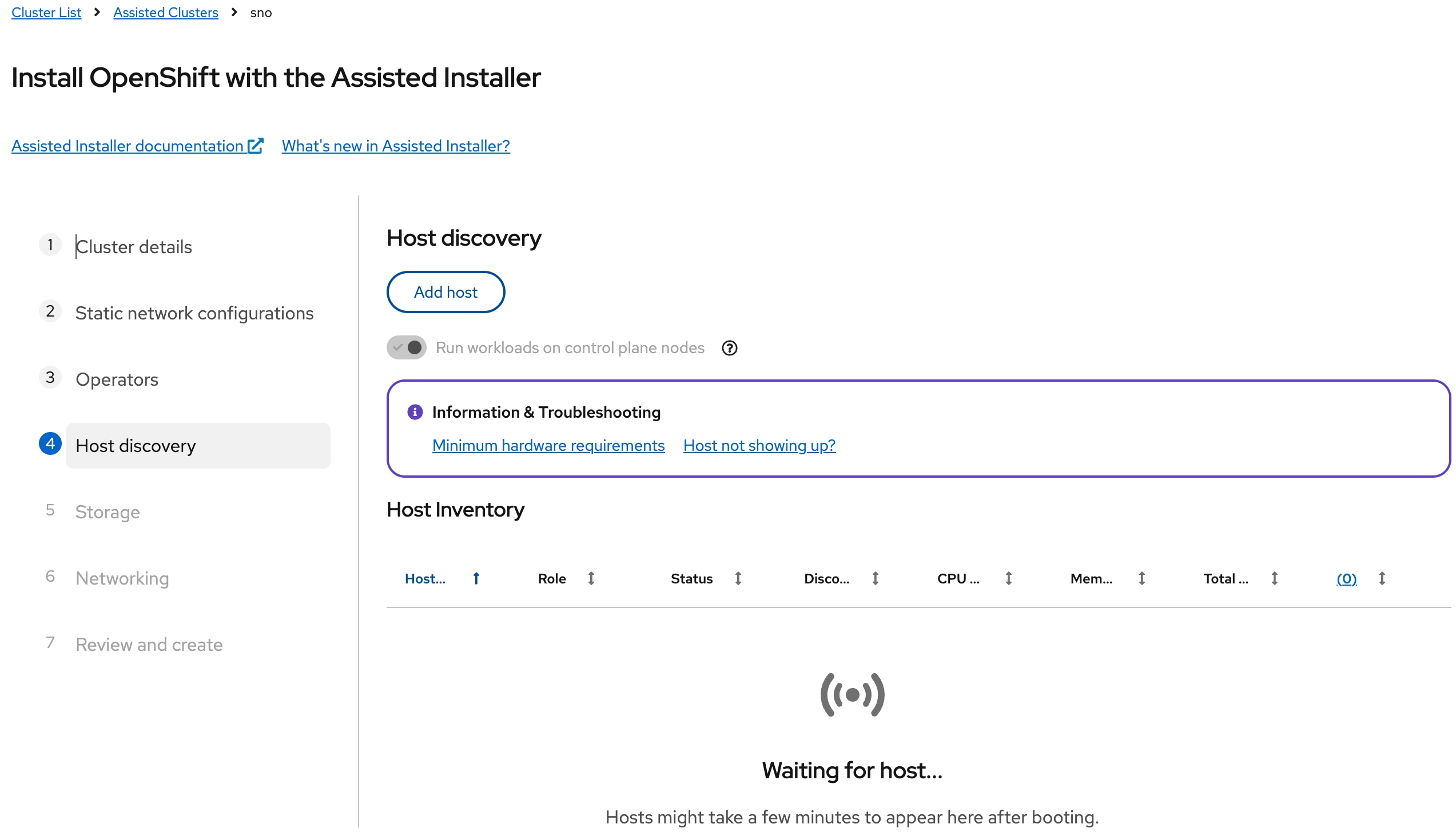
Step 17. On the Add host page, under Provisioning type, select the Full Image file from the drop-down list. Under SSH public key section, click Browse and load the SSH public key file prepared prior to the installation. The contents of the public key should now appear in the box.
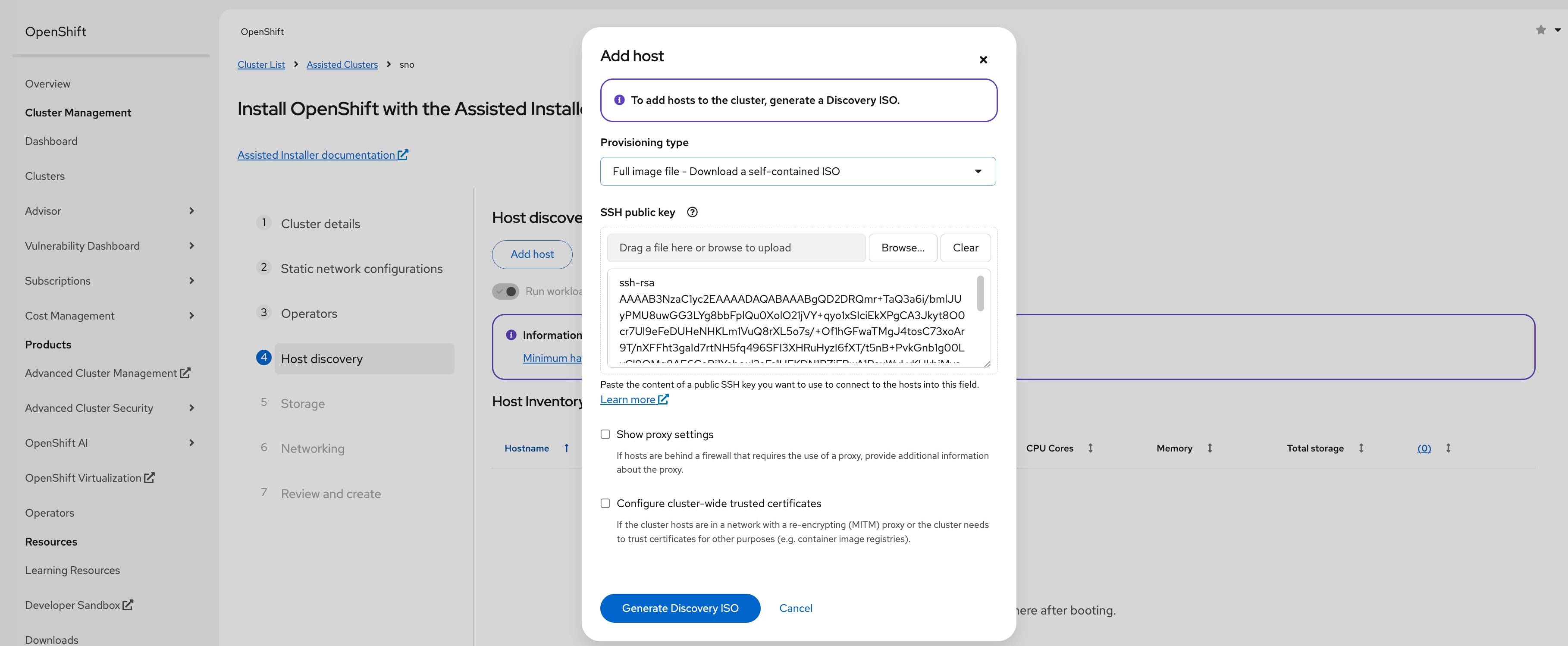
Step 18. Click Generate Discovery ISO.
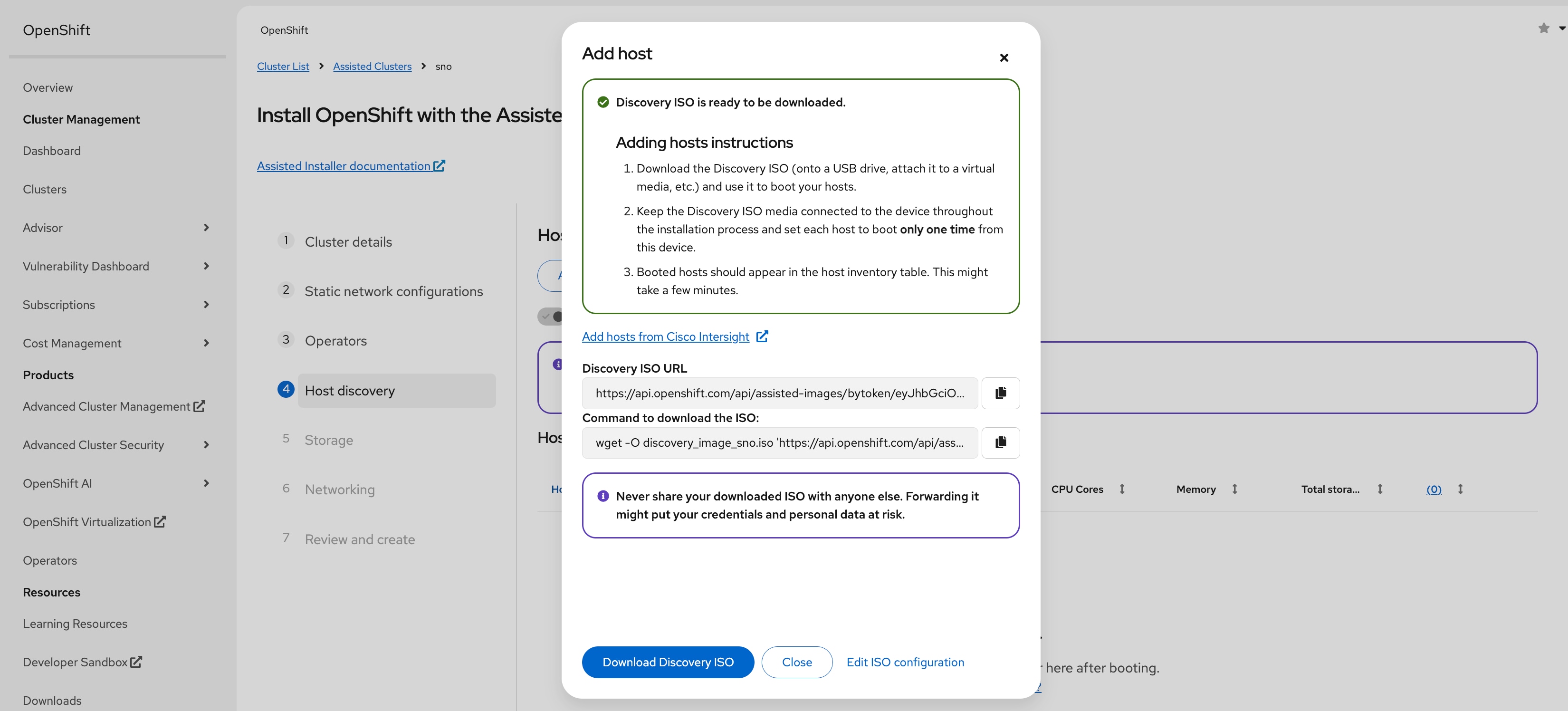
Step 19. Log into Cisco Intersight, go to Configure > Policies and edit the Virtual Media policy attached to your OpenShift server profiles.
Step 20. Once on the Policy Details page, click Add Virtual Media.
Step 21. In the Add Virtual Media dialogue, leave CDD selected and select HTTP/HTTPS. Provide a name for the mount, copy and paste the Discovery ISO URL on Add host page in File Location field and then click Add.
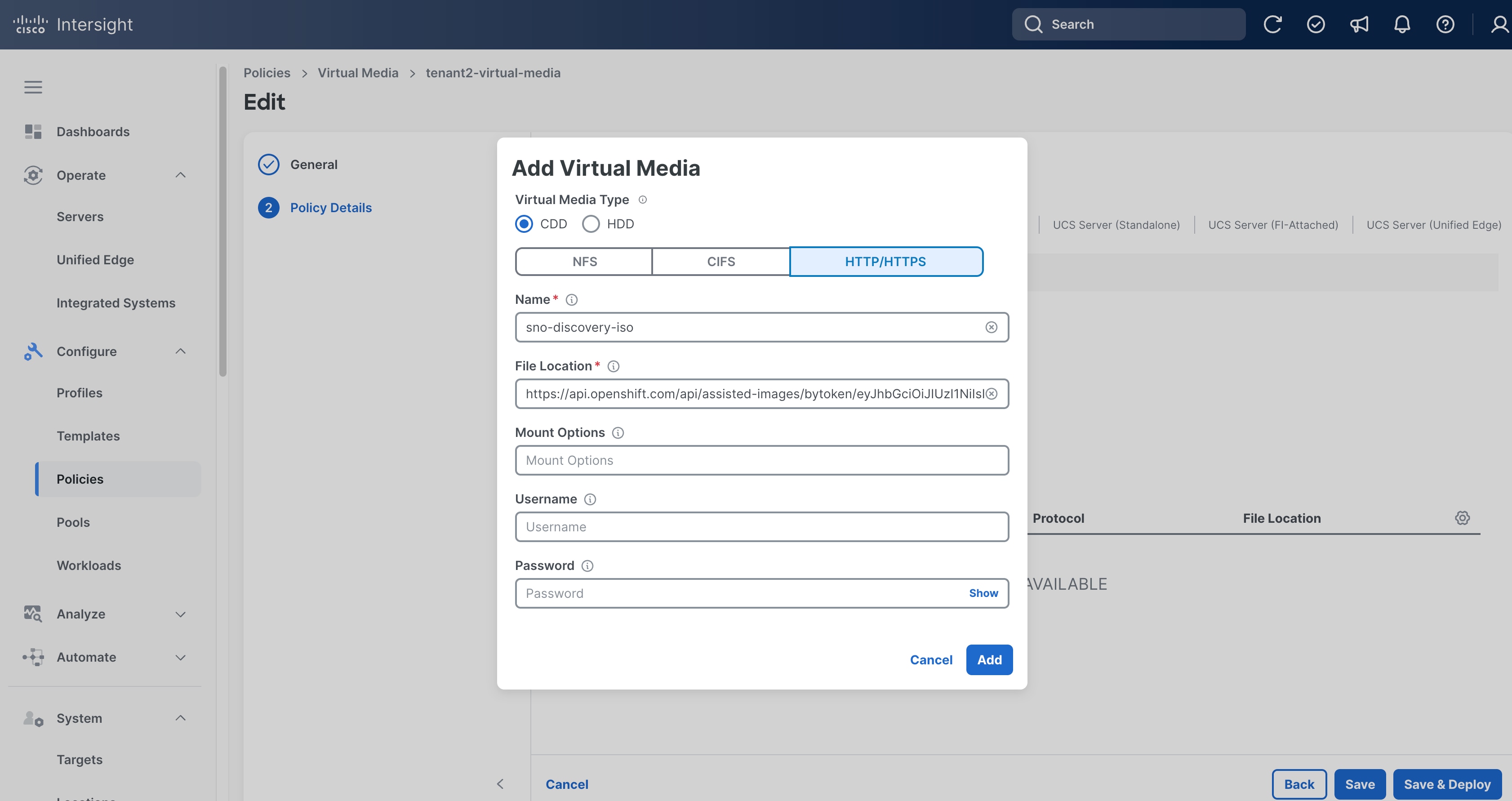
Step 22. From the Policy Details page, click Save & Deploy then click Save & Proceed.
Step 23. On the Deploy Server Profiles confirmation window, select I understand that potential disruption may occur during profile deployment, then click Deploy.
Step 24. Click the checkmark icon at upper-right corner to monitor the status of server profile deployment. It will take a while for Deploy Server Profile requests to reach Success status.
Step 25. Go to Operate > Servers, click the ellipses (…) to the right of the first server and select Power > Power Cycle.
Step 26. On the Power Cycle Server pop-up window, toggle the switch to enable Set One Time Boot Device, then choose cimc-dvd from the Boot Device list. Click Power Cycle.
Step 27. Monitor the process on vKVM or Tunneled vKVM. The server should boot RHEL CoreOS (Live) from the Discovery ISO.
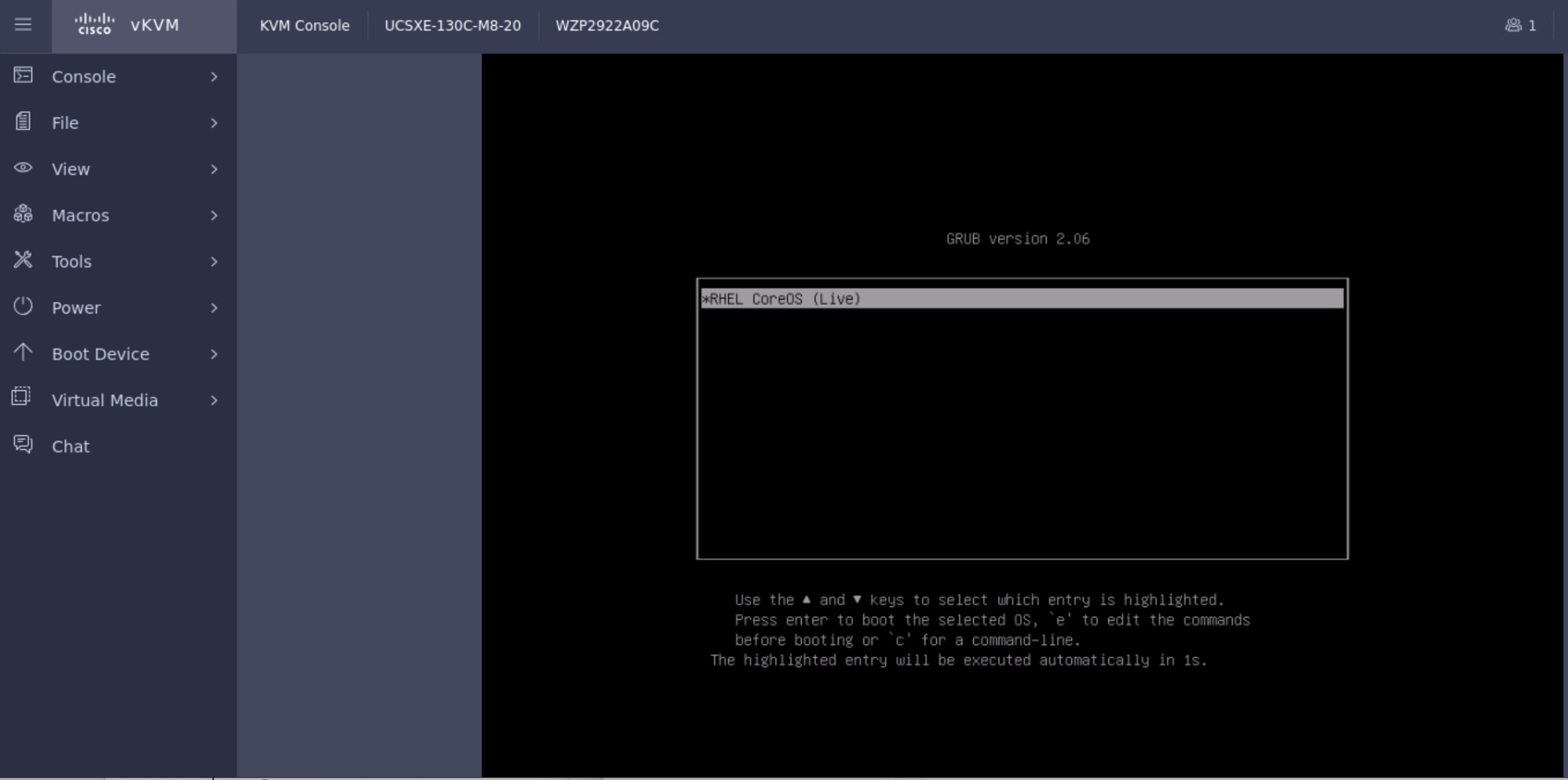
Step 28. When the server has booted RHEL CoreOS (Live) from the Discovery ISO, it will appear in the Host Inventory list on Install OpenShift with the Assisted Installer page on Red Hat Hybrid Cloud Console.
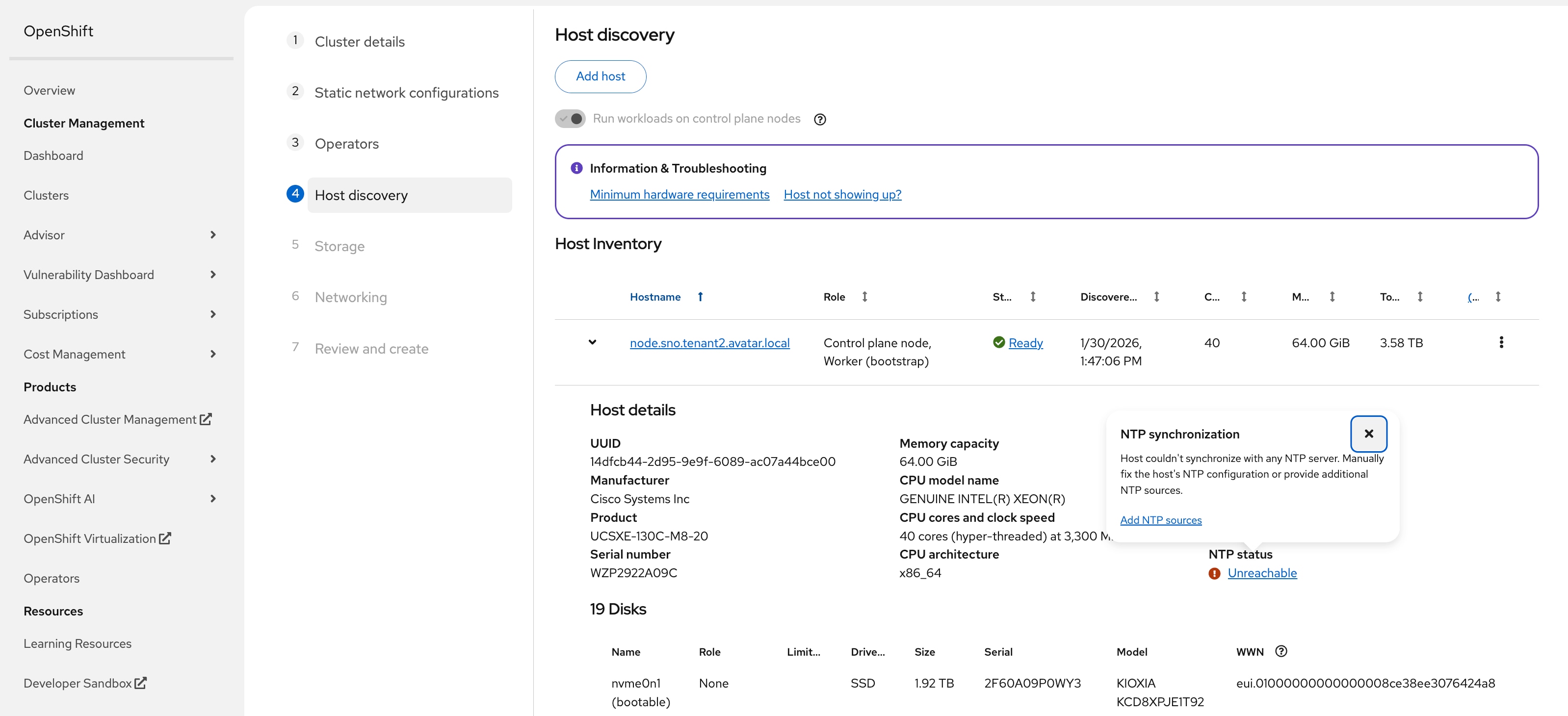
Step 29. Expand the hostname and check the details. You may see NTP status is Unreachable. Click Unreachable, then click Add NTP Sources.
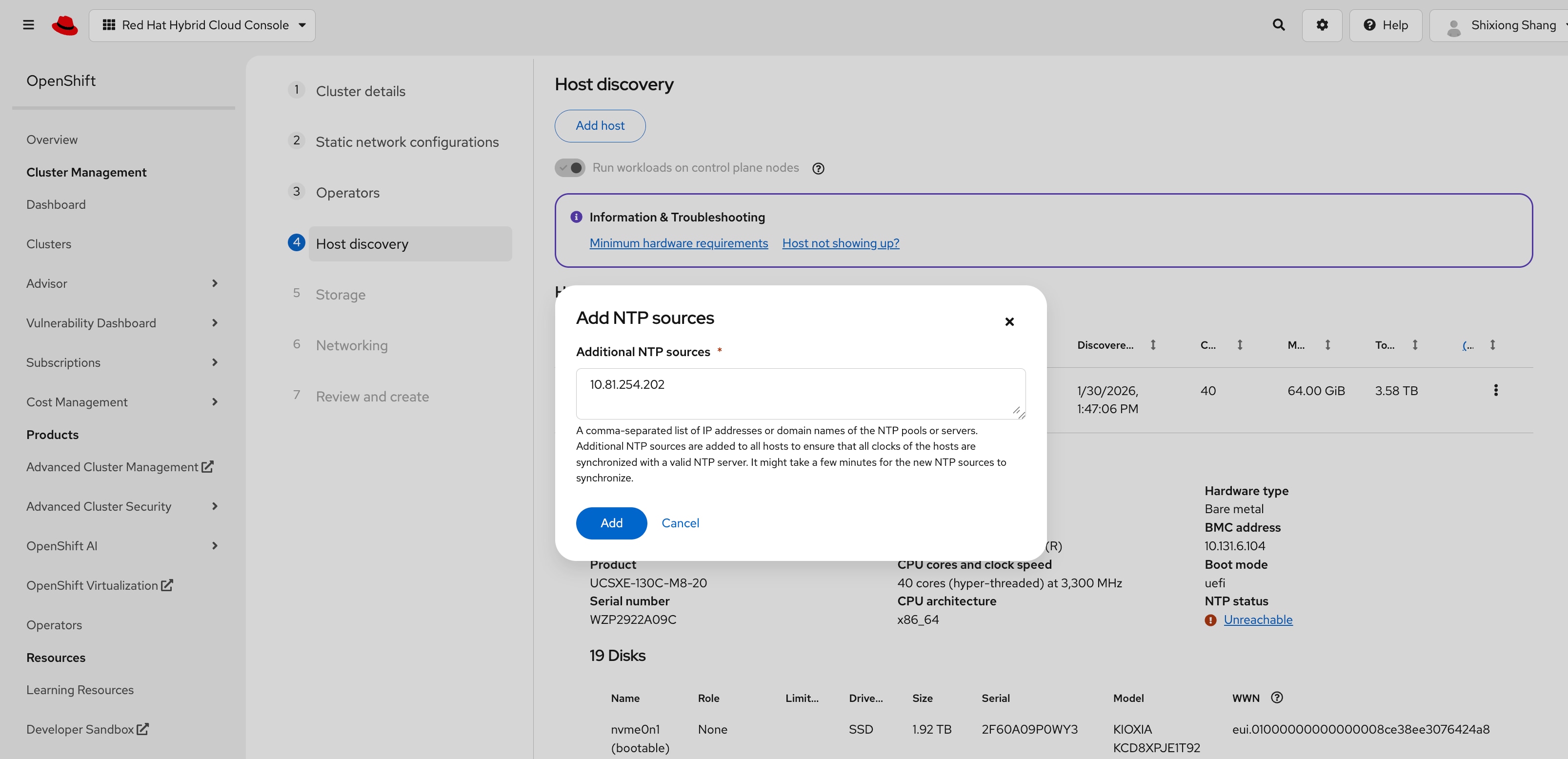
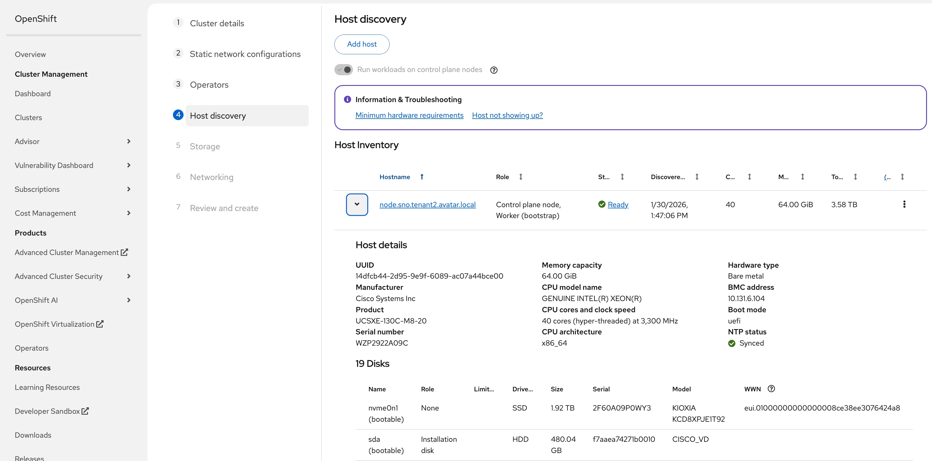
Step 30. In the dialogue window, add the IP address of NTP servers, then click Add. The NTP status will become Synced. It may take a few minutes.
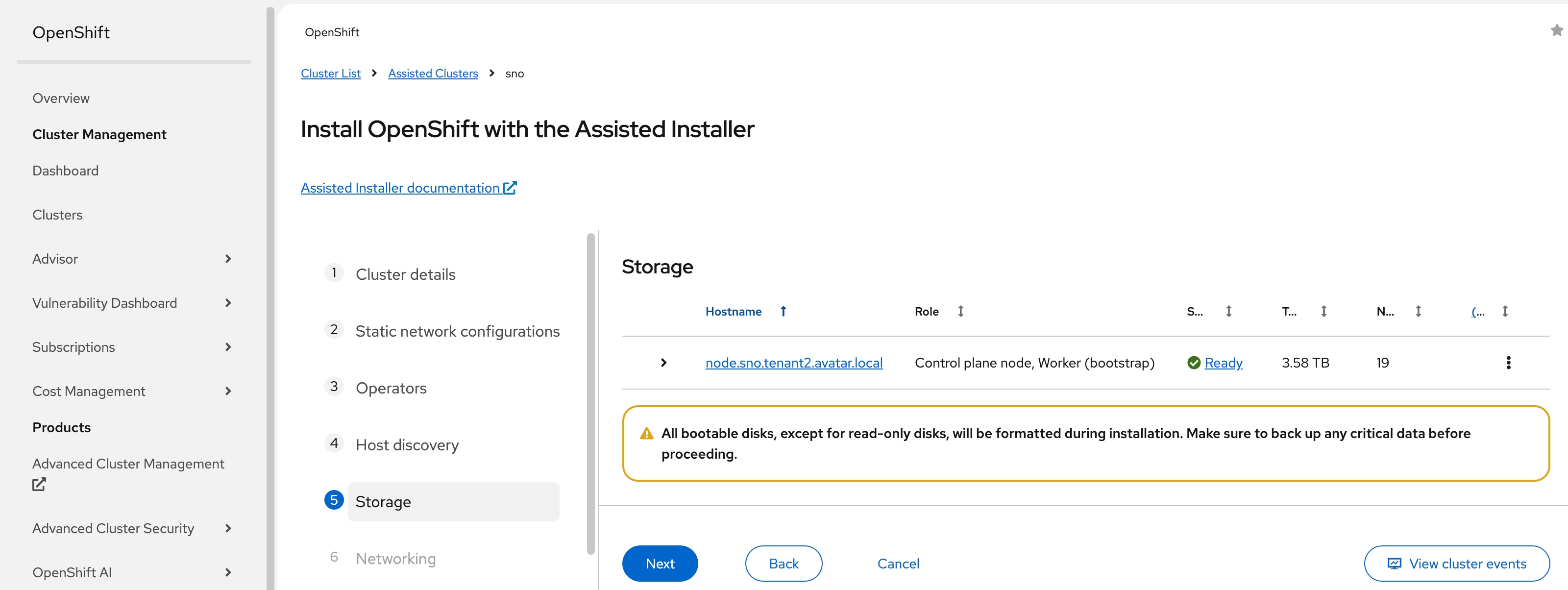
Step 31. Expand the node and confirm that sda is set as the Installation disk. Verify that the NVMe disk nvme0n1 is also visible in the disk list. The NVMe disk will be used for data storage in a later step and should not be selected as the installation disk. Scroll down and click Next.
Step 32. On the Storage page, click Next.
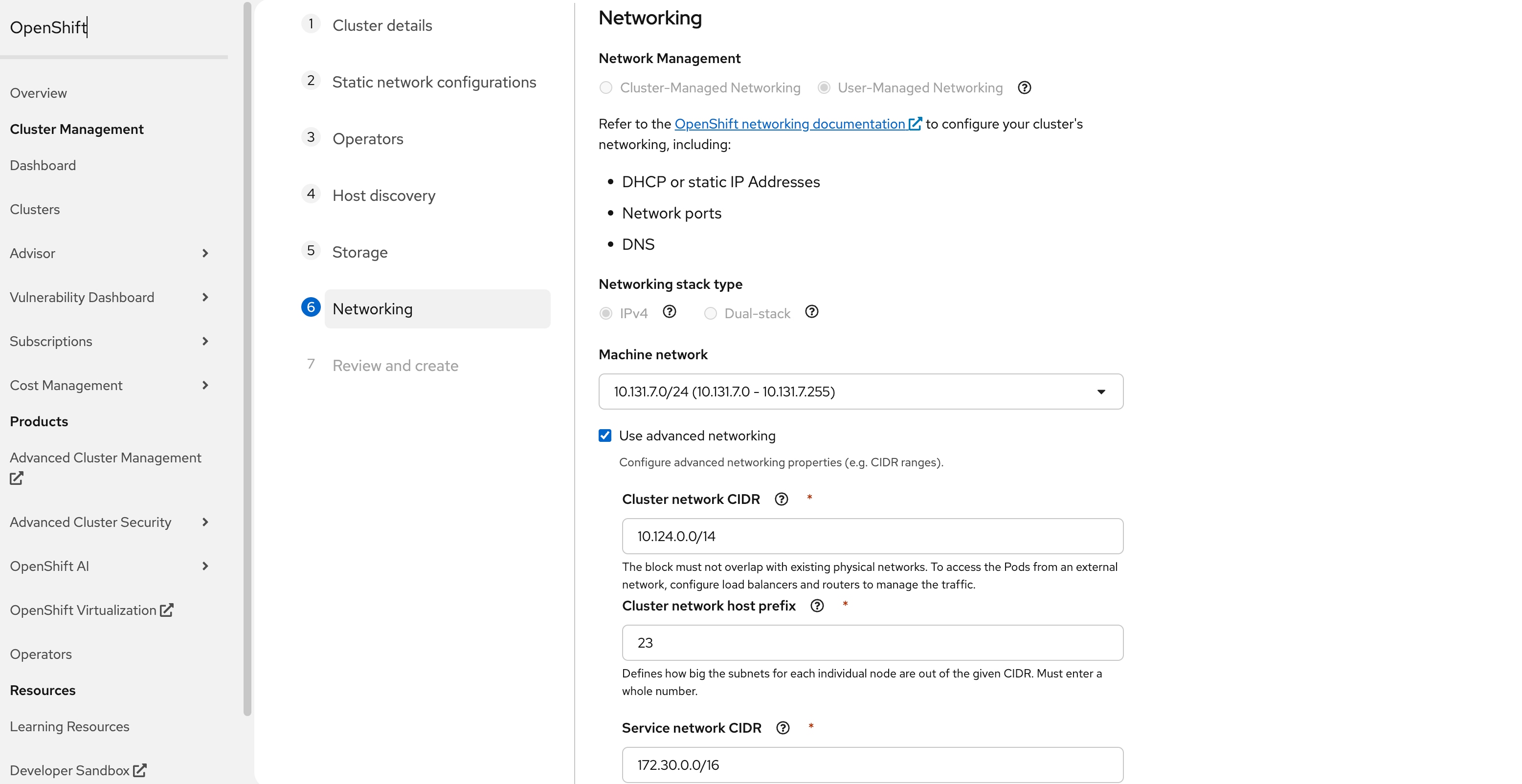
Step 33. (Optional) On the Networking page, select Use advanced networking to change the Cluster network CIDR if the default subnet overlaps with the infrastructure network. In this case, the Cluster network CIDR is changed from the default 10.128.0.0/14 to 10.124.0.0/14 and then click Next.
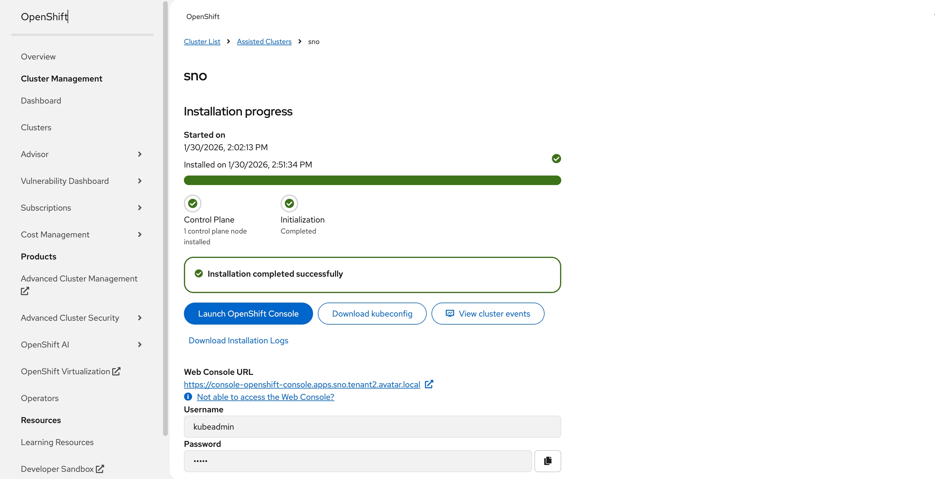
Step 34. On the Review and create page, click Install cluster to begin the cluster installation. The installation will take 30-45 minutes.
Procedure 3. Access OpenShift by OC CLI
Step 1. After installation is successful, select Download kubeconfig to download the kubeconfig file.
Step 2. Follow the instruction in Red Hat document to enable oc to use the downloaded kubeconfig file: https://docs.redhat.com/en/documentation/openshift_container_platform/4.19/html/cli_tools/openshift-cli-oc
Step 3. Verify the access to OpenShift cluster:
$ oc get nodes
NAME STATUS ROLES AGE VERSION
node.sno.tenant2.avatar.local Ready control-plane,master,worker 2d20h v1.32.10
Procedure 4. Access OpenShift Web Console
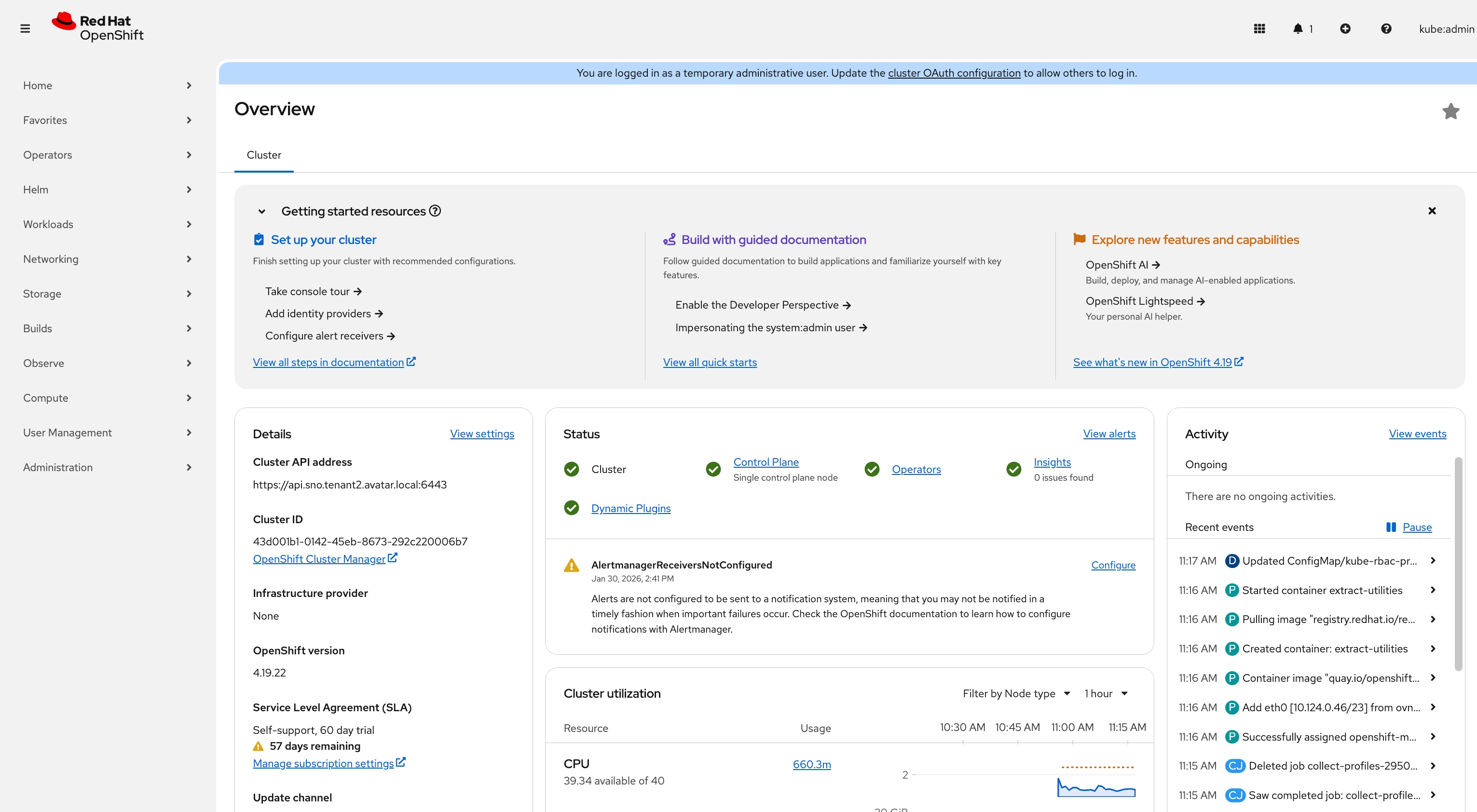
Step 1. After installation is successful, click Web Console URL and log in with Username (for example, kubeadmin) and Password provided by the installation process.
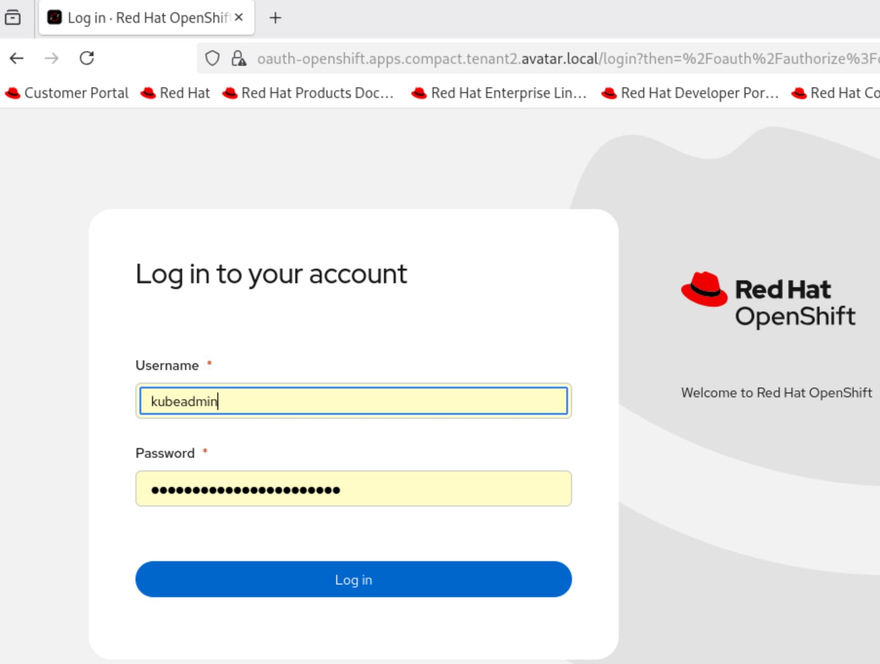
You will see the landing page upon a successful login.
Install OpenShift Operators
Procedure 1. Install Kubernetes NMState Operator
Step 1. Log into the OpenShift web console with cluster administrator credentials.
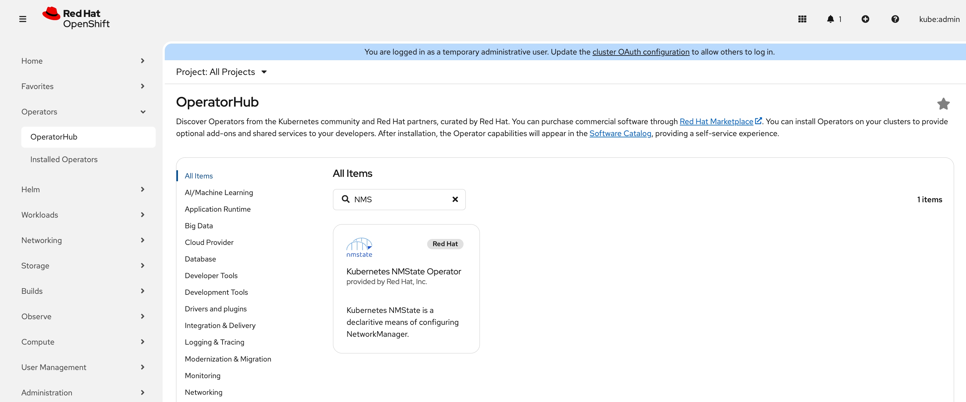
Step 2. Go to Operators > OperatorHub, enter NMState, and the Kubernetes NMState Operator should appear. Click Kubernetes NMState Operator.
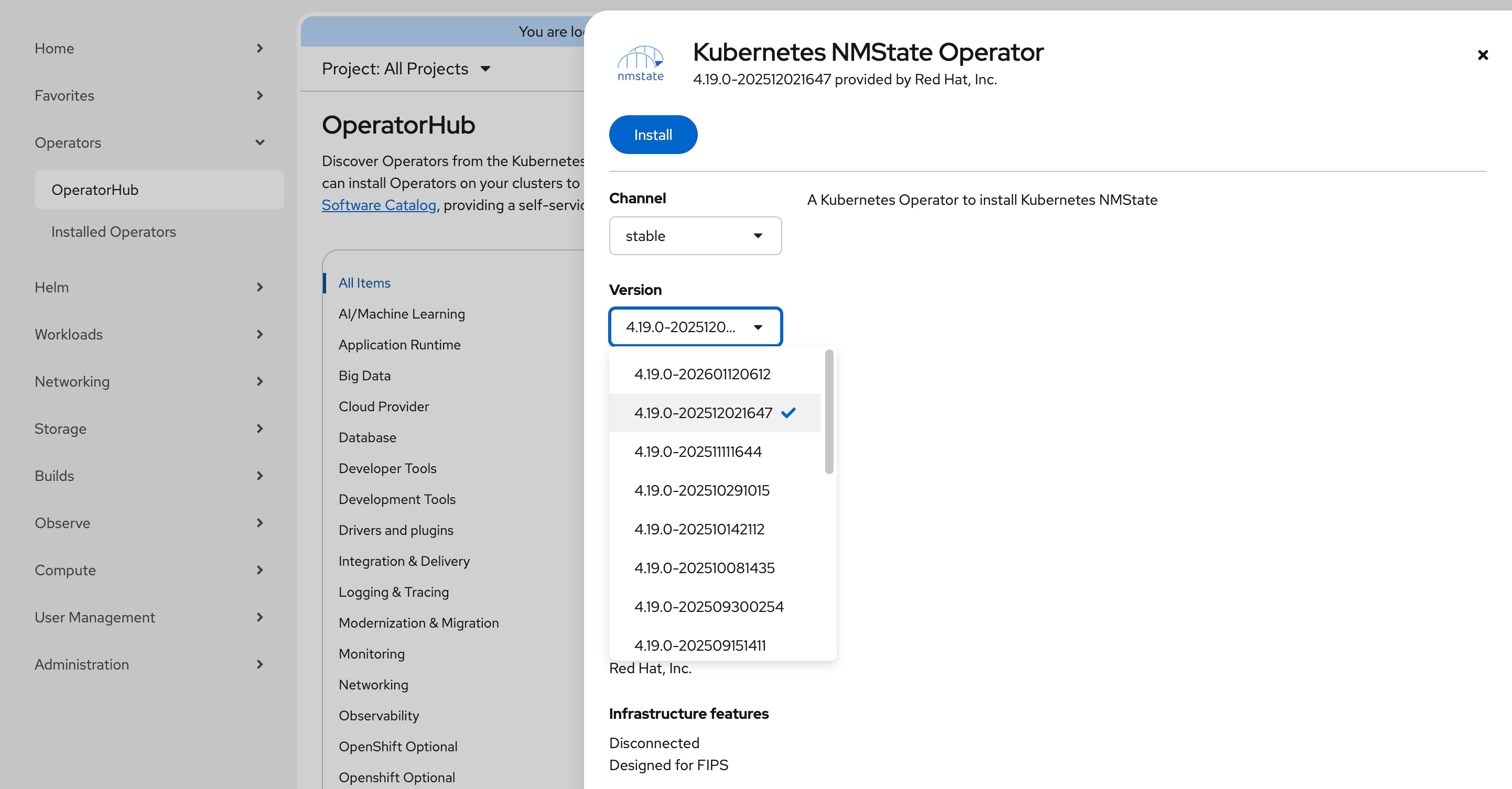
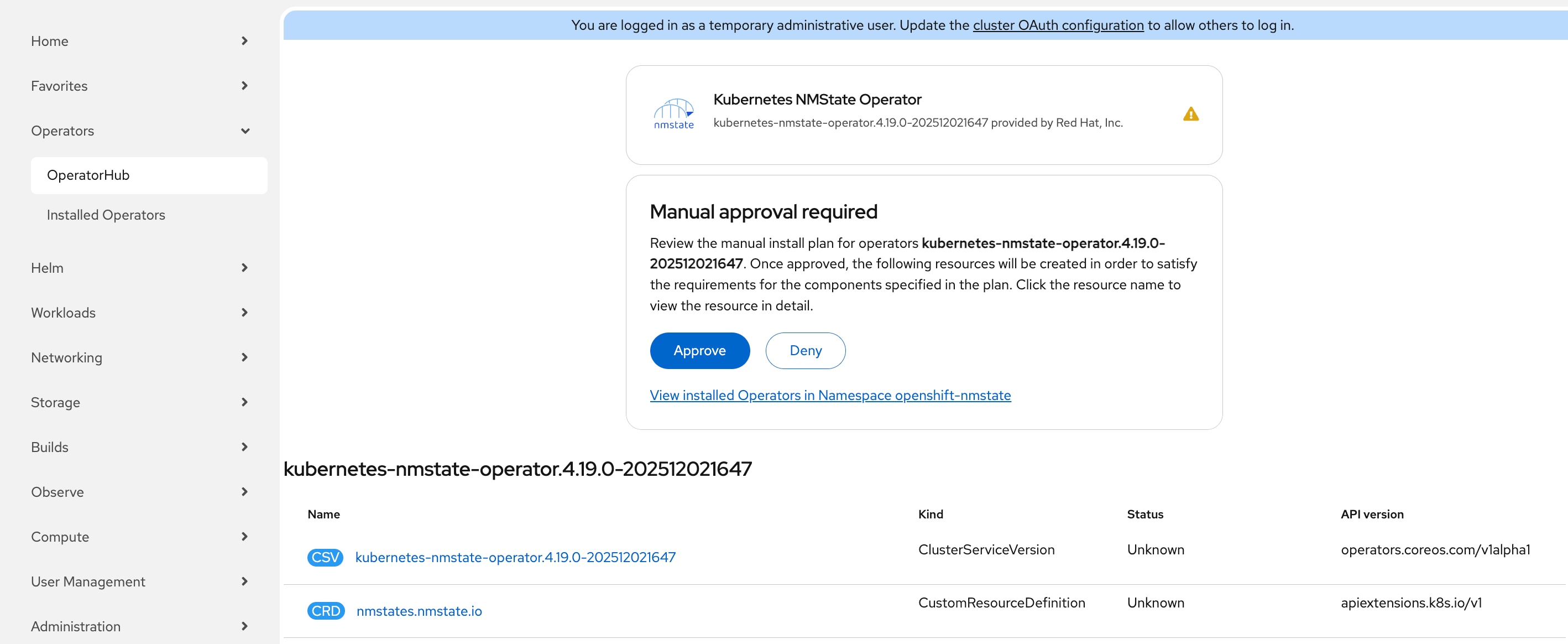
Step 3. On the Kubernetes NMState Operator page, in the Version drop-down list, choose 4.19.0-202512021647 release and click Install.
Note: This guide uses version 4.19.0-202512021647 which has been validated with OpenShift 4.19.22. If you choose to use a later version, verify compatibility in the Red Hat documentation.
Step 4. On the Install Operator page, leave all the defaults in place and click Install.
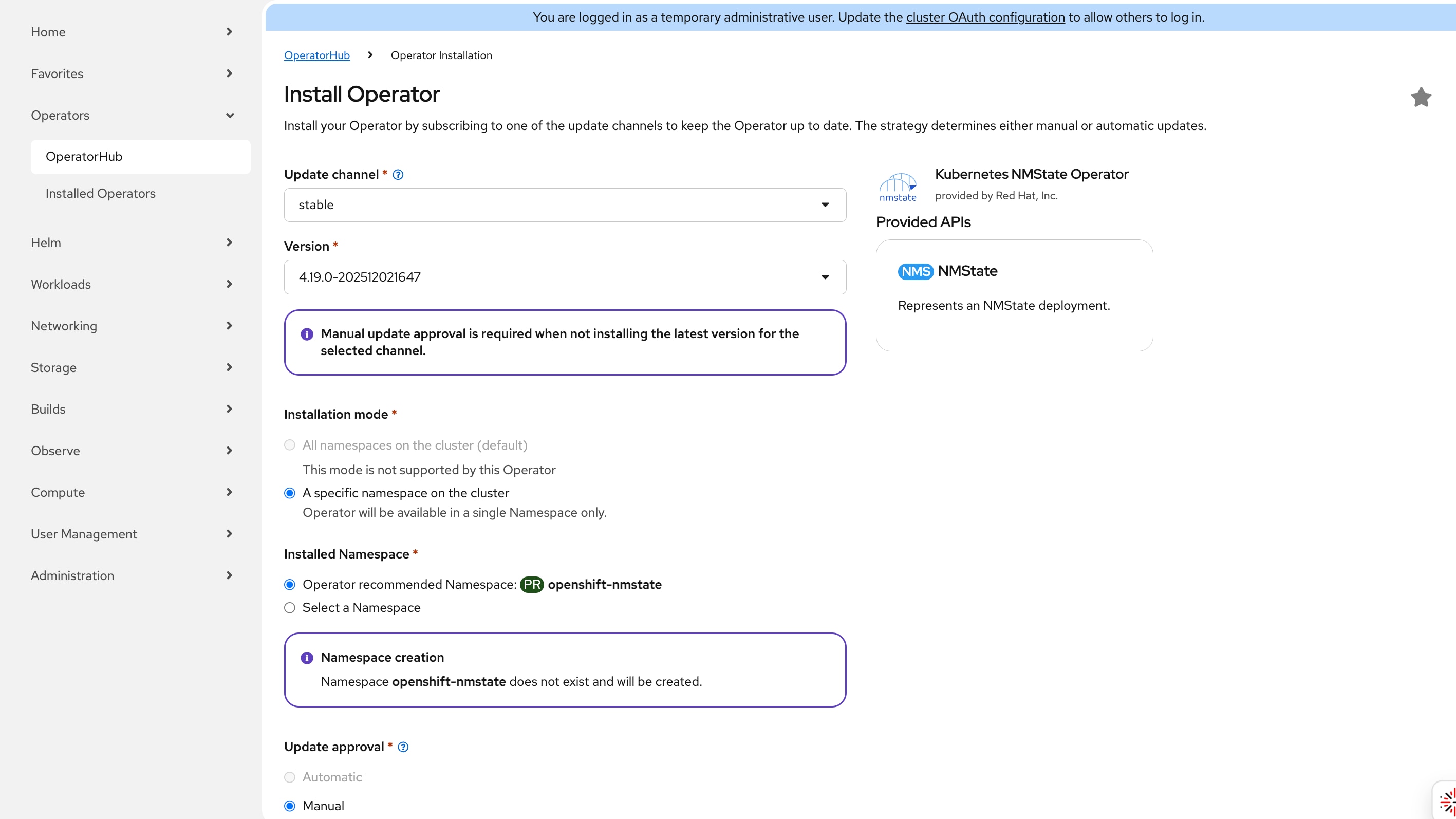
Step 5. In Manual approval required box, click Approve. It will take a few minutes for the installation to complete.
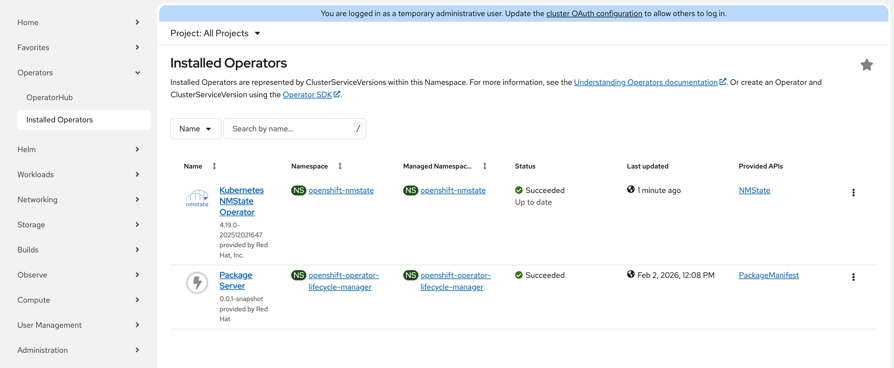
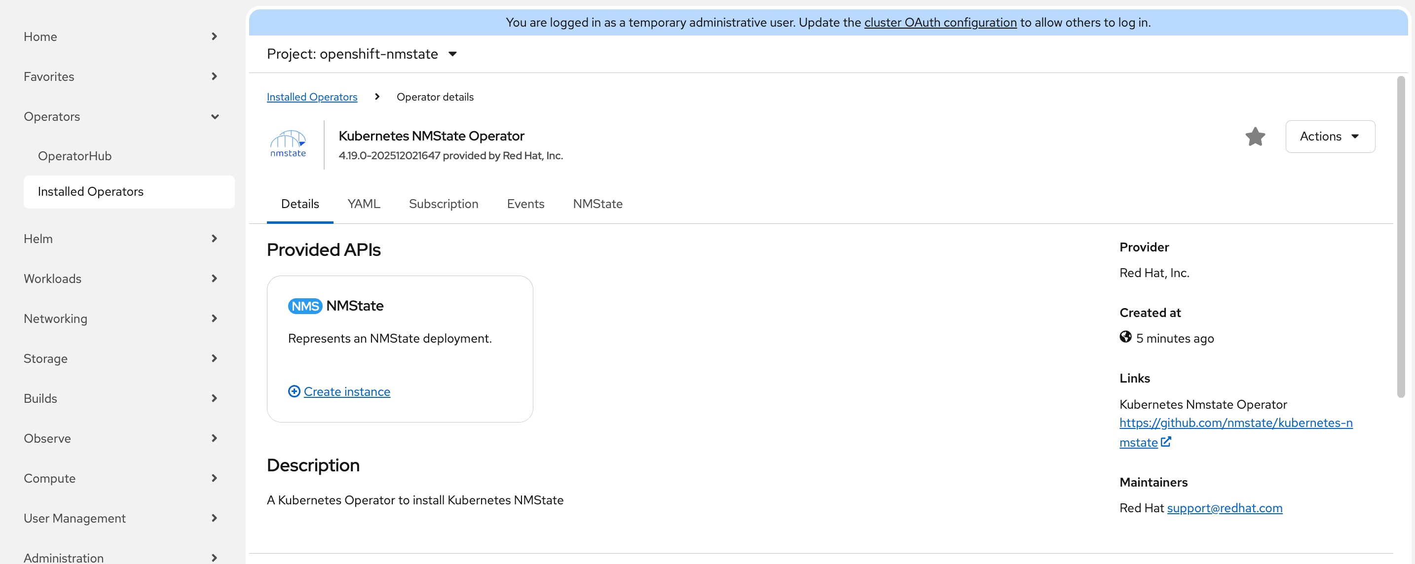
Step 6. Go to Operators > Installed Operators and the Status of the Kubernetes NMState Operator should be Succeeded and then click Kubernetes NMState Operator.
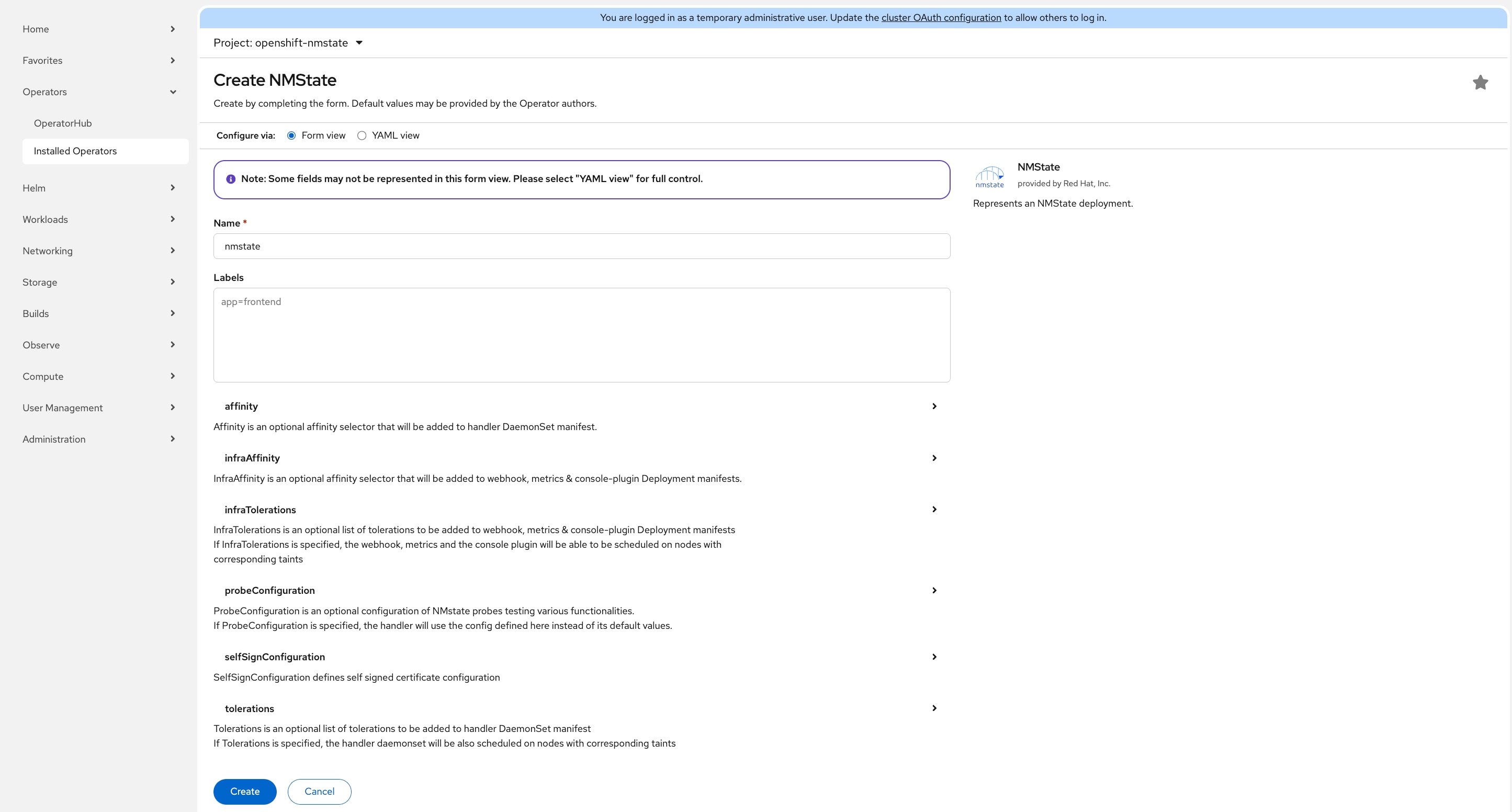
Step 7. On the Operator details page, click the Details tab, in the NMState block section, select Create instance.
Step 8. On the Create NMState page, leave all defaults in place and click Create.
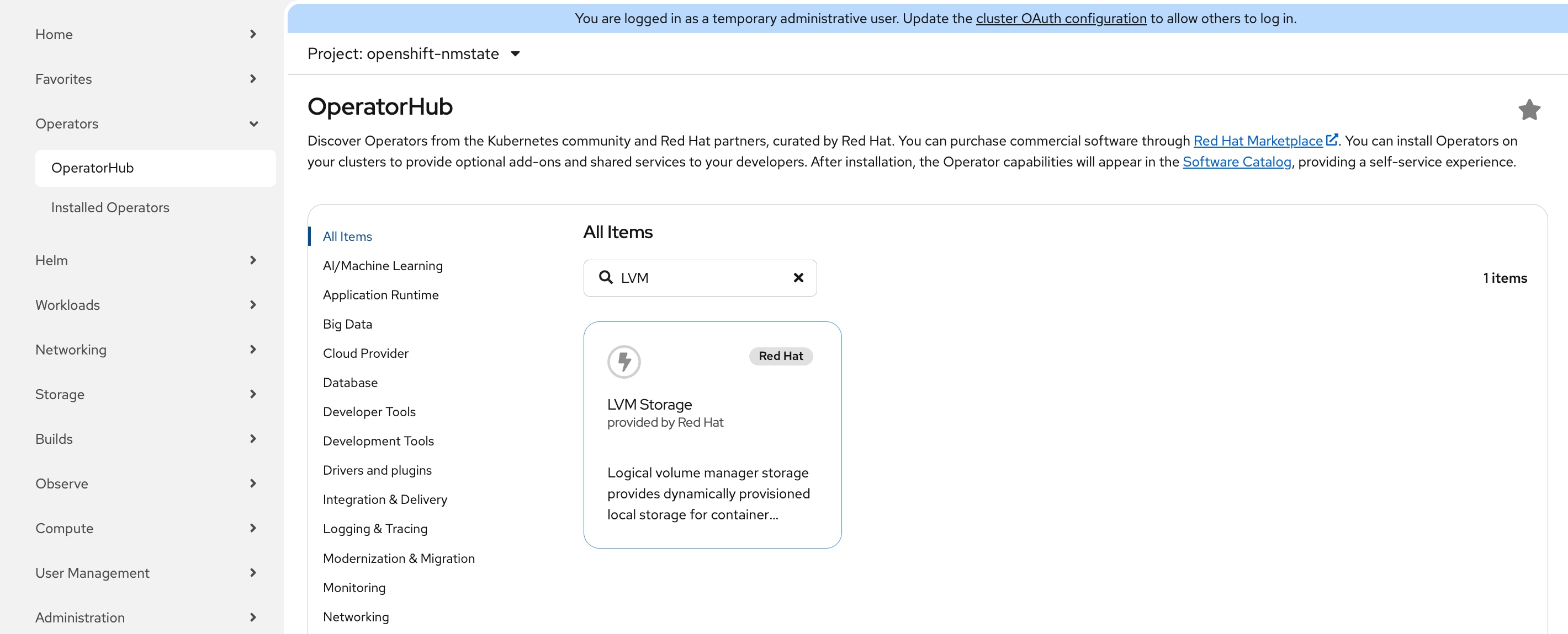
Procedure 2. Install LVM Storage Operator
Step 1. Go to Operators > OperatorHub, enter LVM, and the LVM Storage should appear. Click LVM Storage.
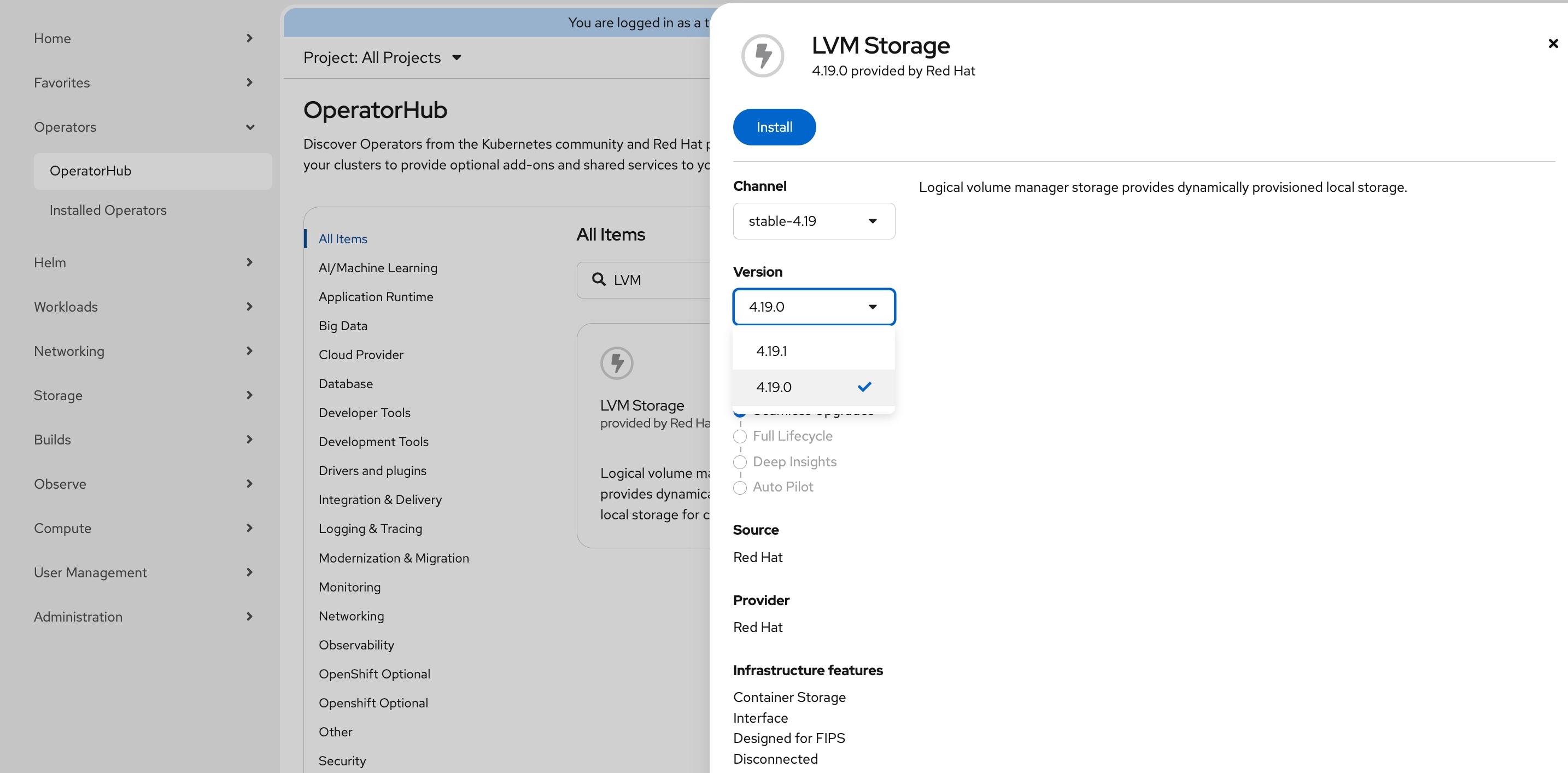
Step 2. On the LVM Storage page, select Version 4.19.0 from the drop-down list. Click Install.
Note: This guide uses version 4.19.0 which has been validated with OpenShift 4.19.22. If you choose to use a later version, verify compatibility in the Red Hat documentation.
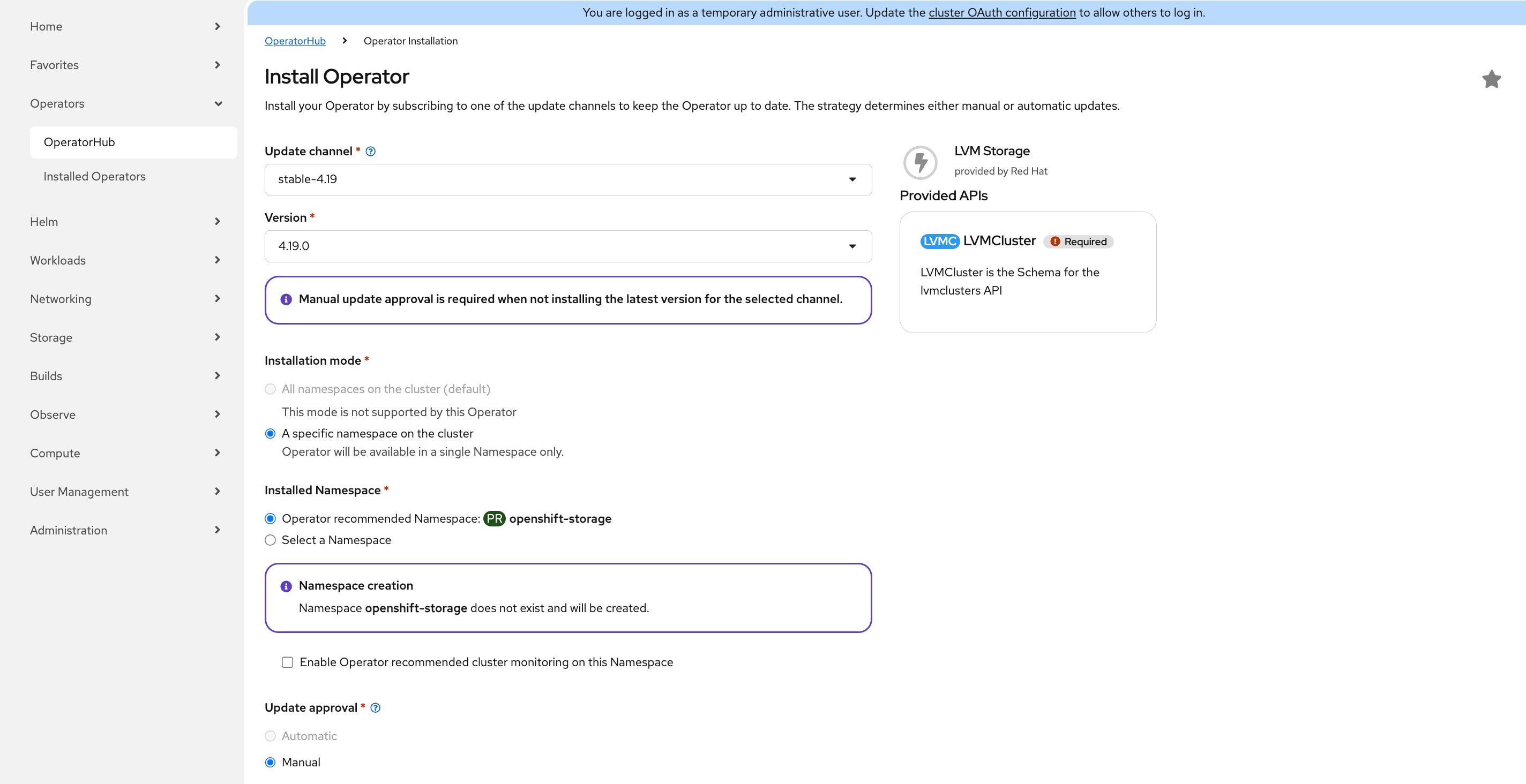
Step 3. On the Install Operator page, leave all the defaults in place and click Install.
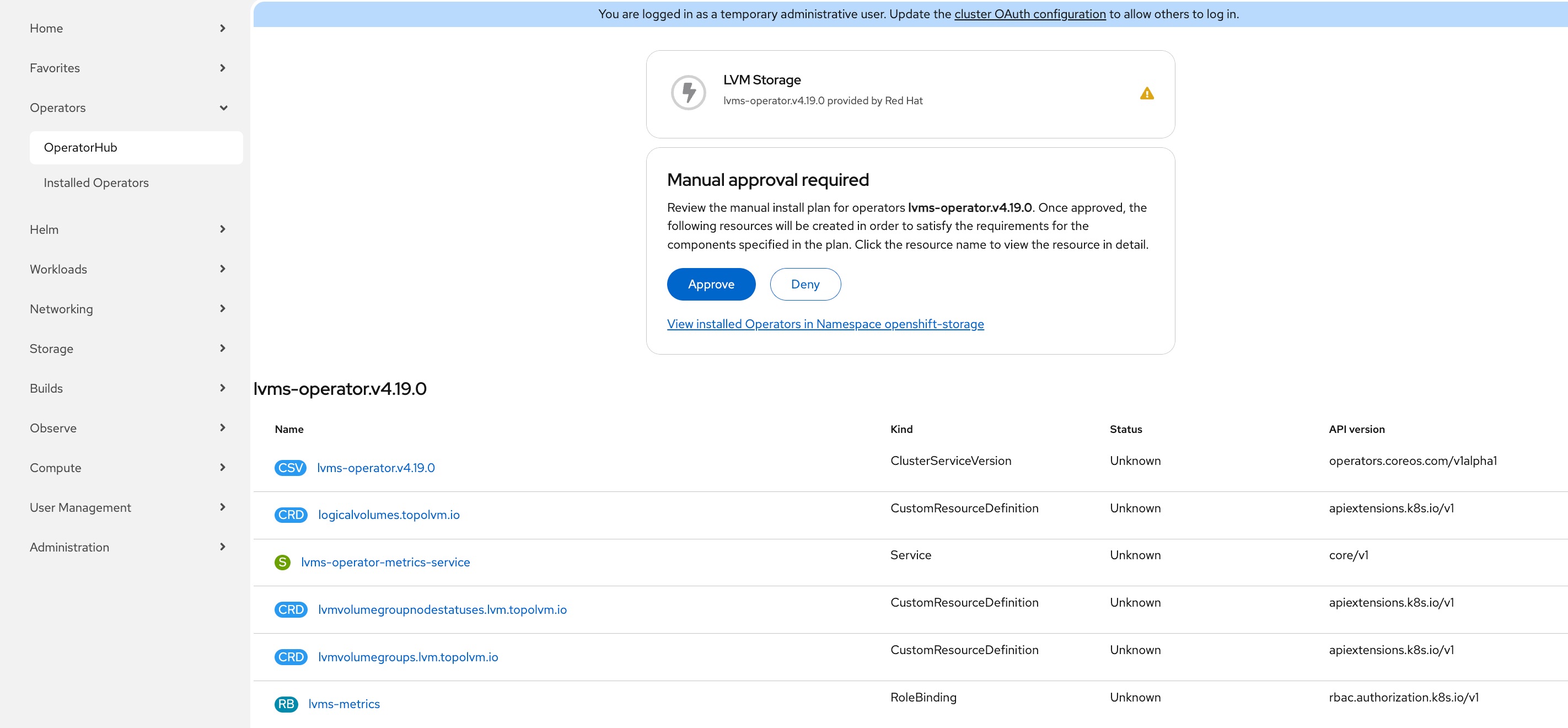
Step 4. On the Manual approval required dialogue, click Approve. The installation will take a few minutes to complete.
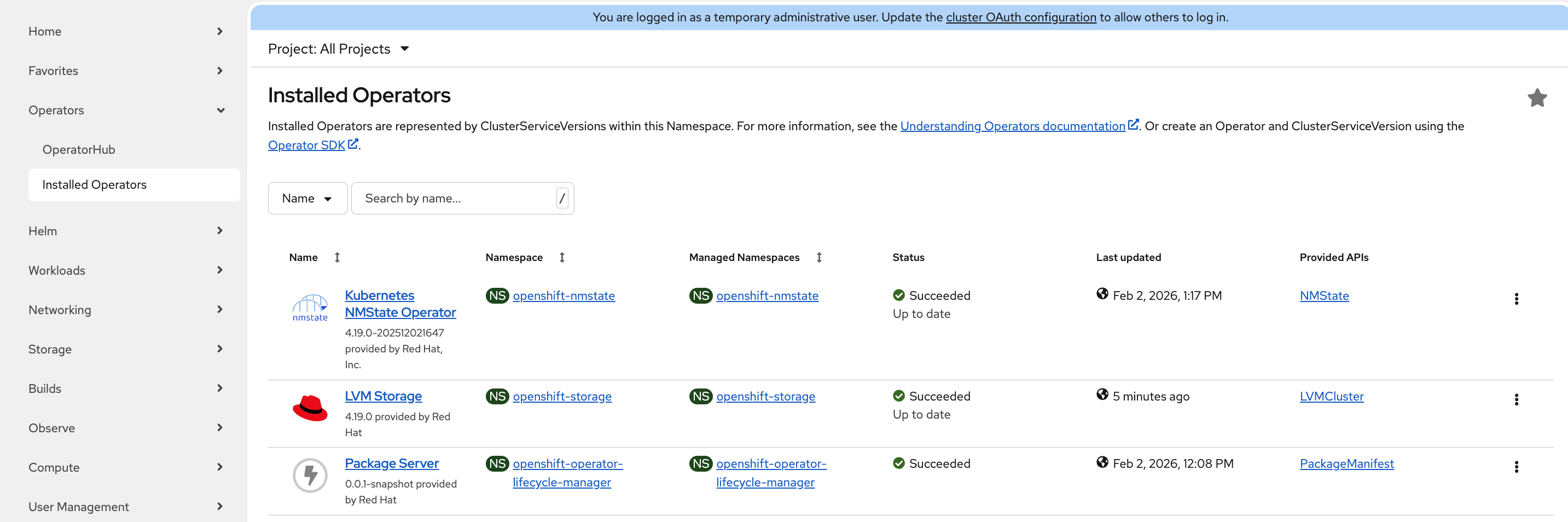
Step 5. Go to Operators > Installed Operators. The Status of LVM Storage should be Succeeded. Click LVM Storage.
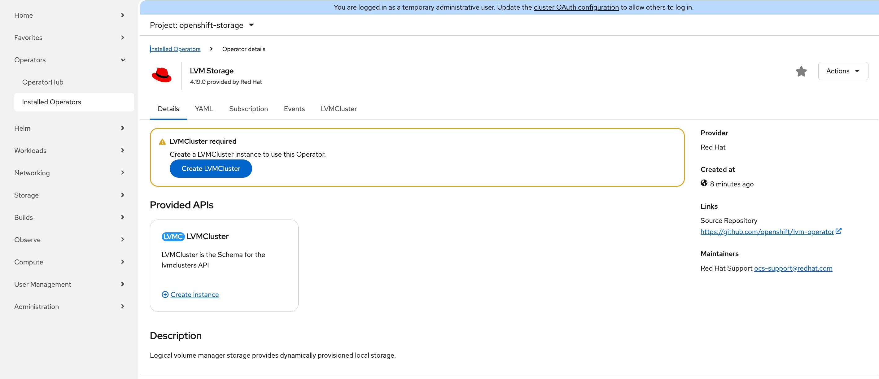
Step 6. On the Operator details page, click th Details tab, then click Create LVMCluster.
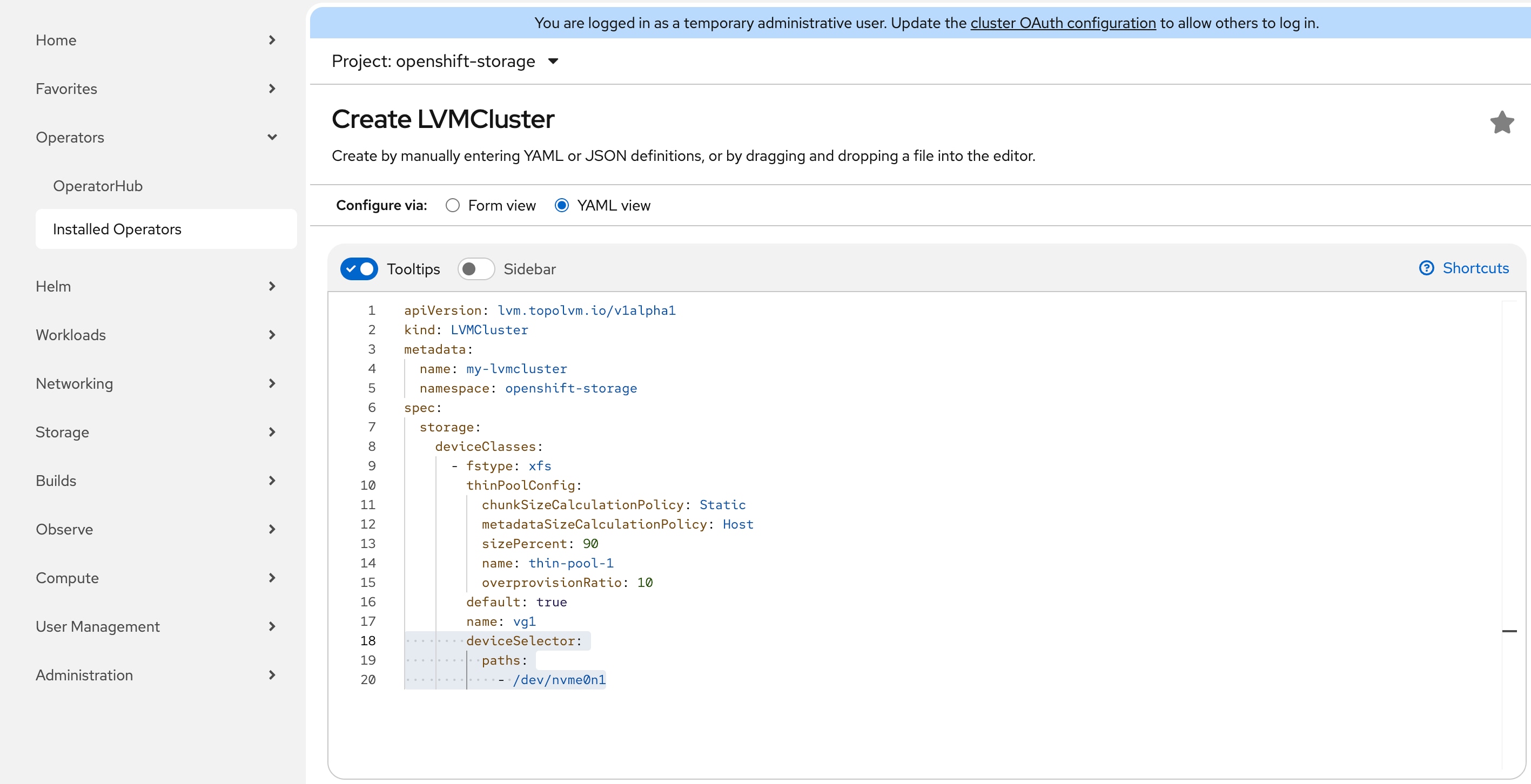
Step 7. On the Create LVMCluster page, click YAML view, add the following lines to the bottom of the YAML file and leave all other fields untouched. Click Create.
deviceSelector:
paths:
- /dev/nvme0n1
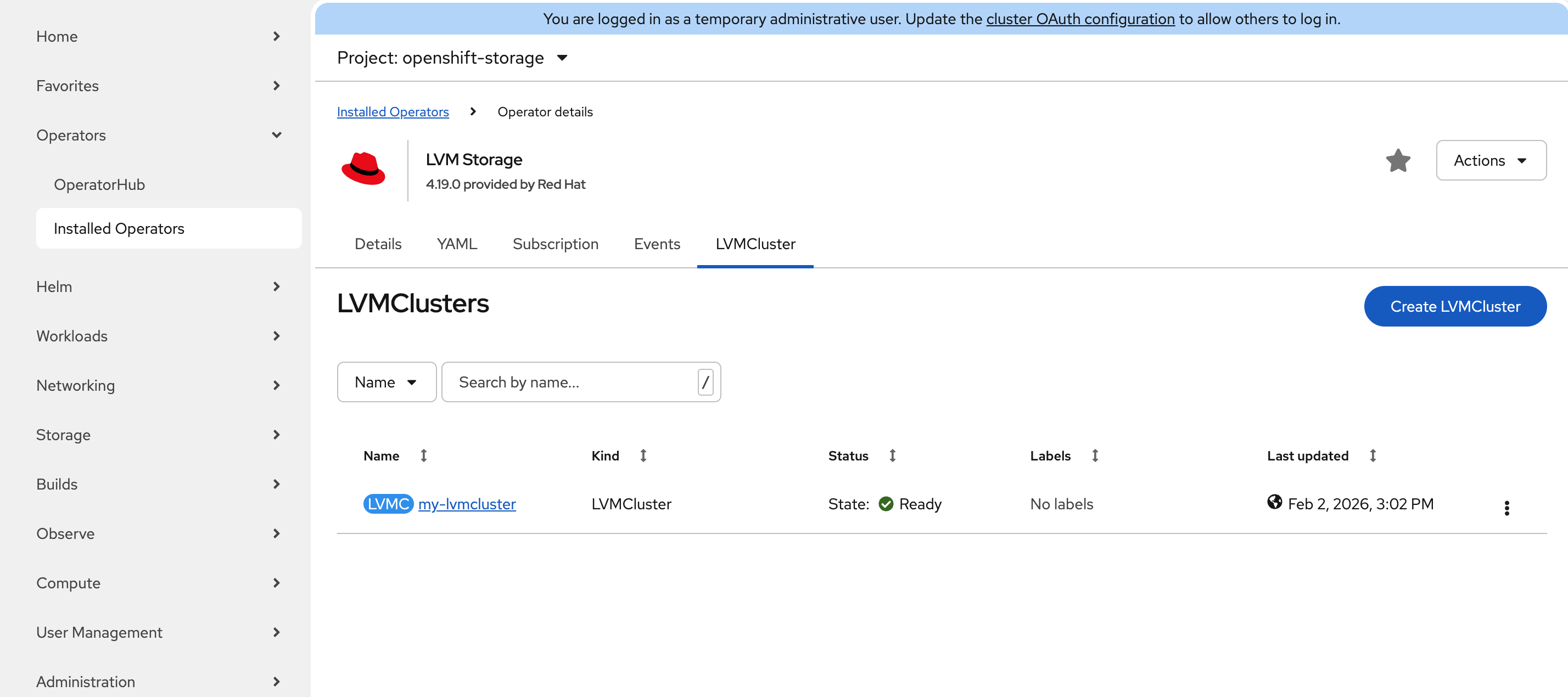
Step 8. From the Operator details page, click the LVMCluster tab. The LVMCluster instance should be in the Ready state.
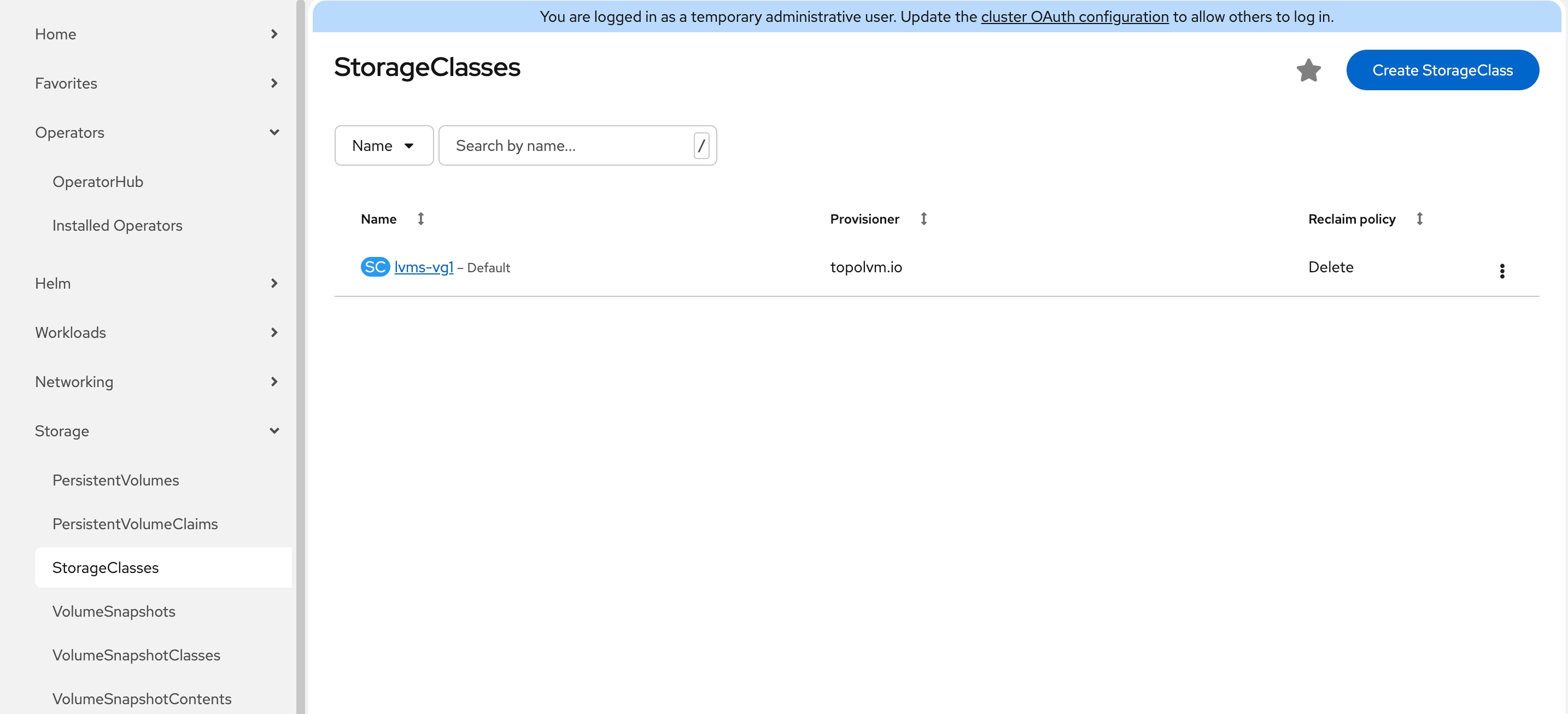
Step 9. Go to Storage > StorageClasses page, verify a new storageclass lvms-vg1 is created successfully.
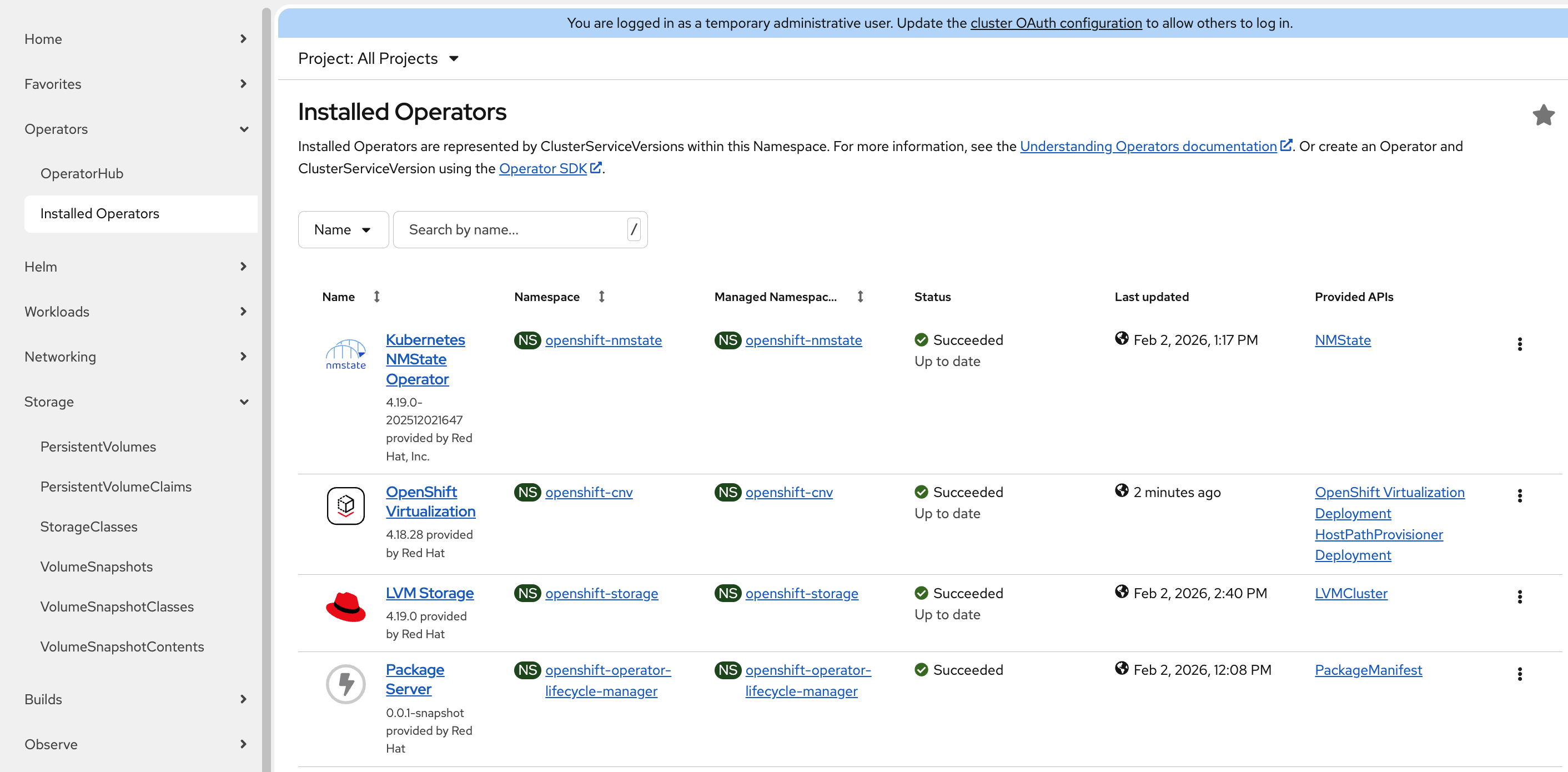
Procedure 3. Install OpenShift Virtualization Operator
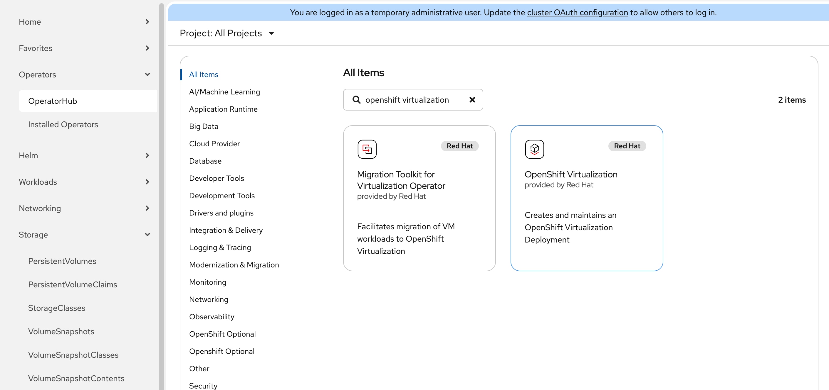
Step 1. In the OpenShift web console, go to Operators > OperatorHub. In the search box, type openshift virtualization. Select OpenShift Virtualization.
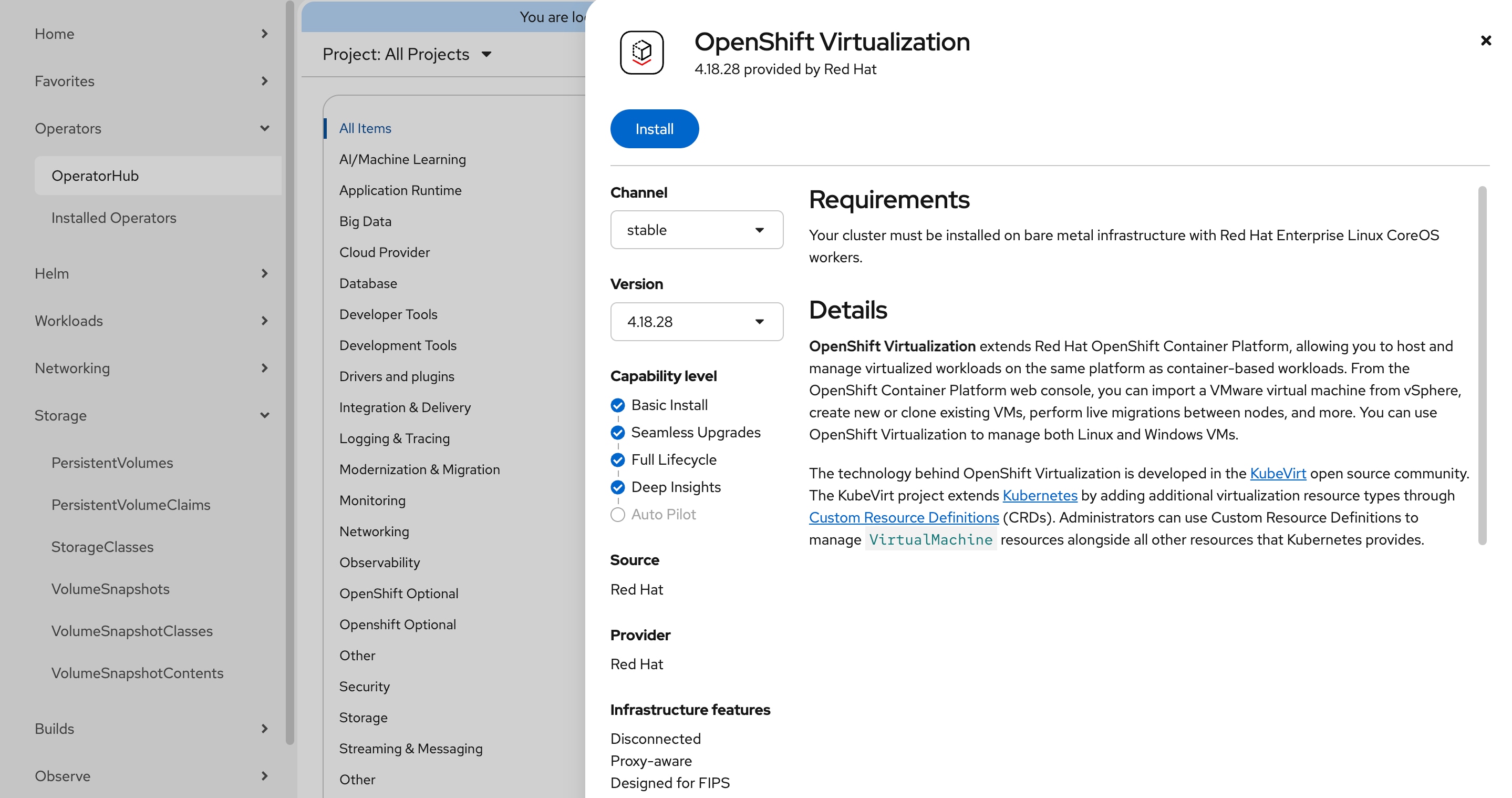
Step 2. On the OpenShift Virtualization page, leave all defaults in place and click Install.
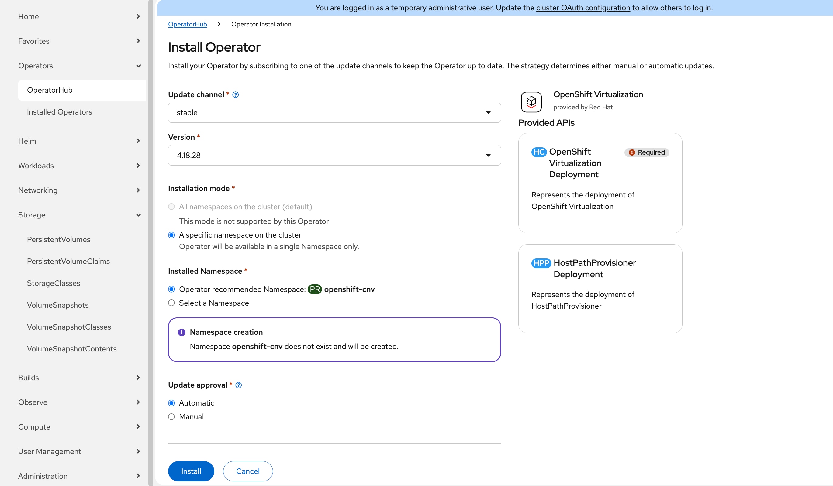
Step 3. On the Install Operator page, leave all defaults in place and click Install again to deploy OpenShift Virtualization in the openshift-cnv namespace. The installation will take a few minutes to complete.
Step 4. Go to Operators > Installed Operators, the status of OpenShift Virtualization operator should be Succeeded.
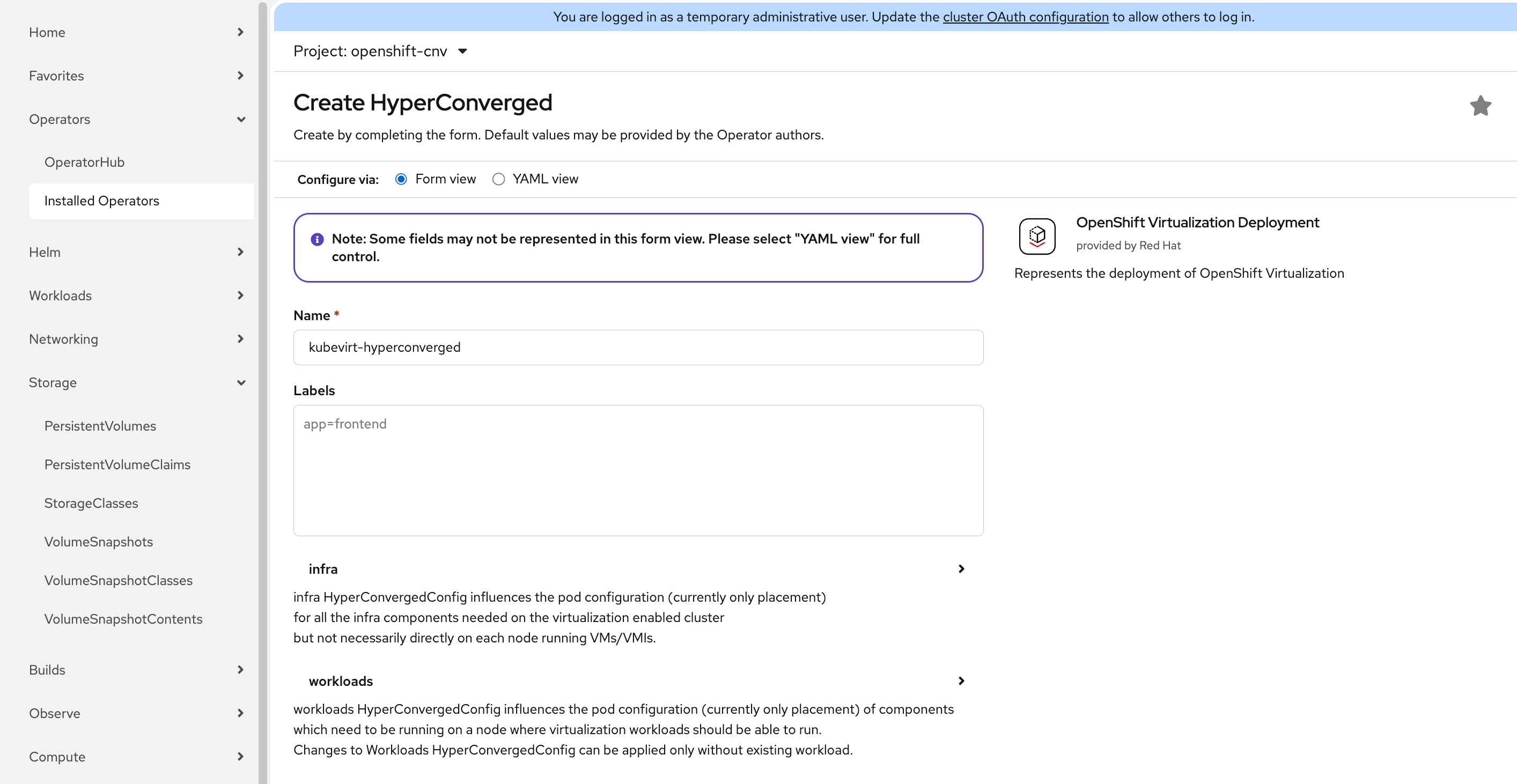
Step 5. Click OpenShift Virtualization, on the Operator details page, click Create HyperConverged.
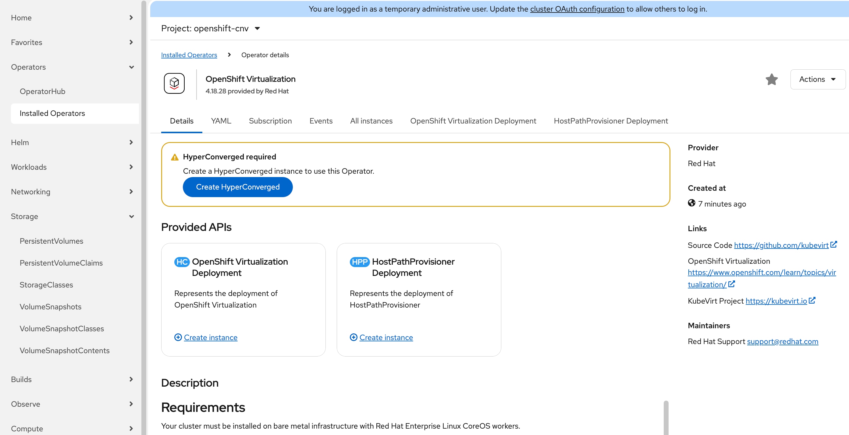
Step 6. On the Create HyperConverged page, leave all defaults in place and click Create. It will take a few minutes for the installation to complete.
Note: You may get logged out of the OpenShift console. This is normal. Just log back in with the cluster administrator privilege.
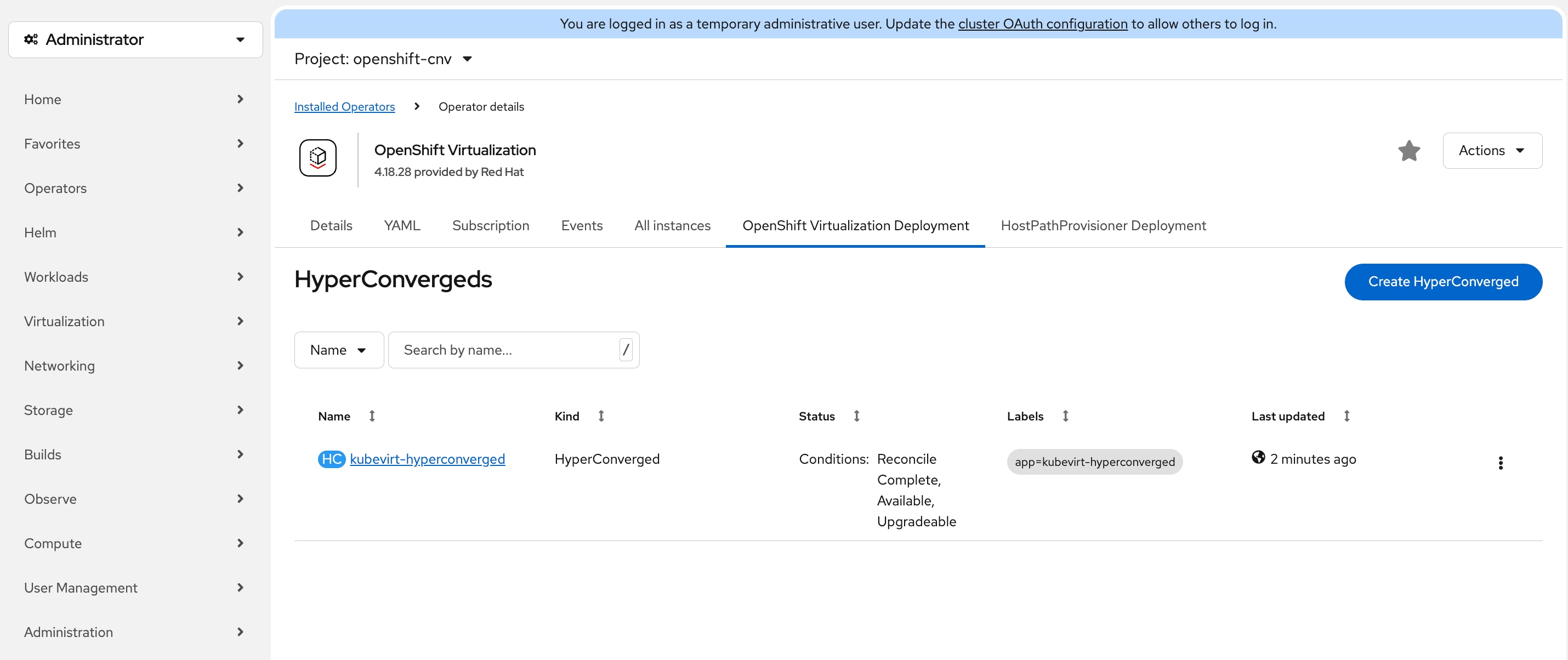
Step 7. Go back to the Operator details page for OpenShift Virtualization. Click the OpenShift Virtualization Deployment tab, the status of HyperConverged instance should be Conditions: Reconcile, Complete, Available, Upgradeable.
Step 8. In the OpenShift web console left navigation menu, verify that the Virtualization menu item is now available.
Procedure 4. Create VM Secondary Network (Optional)
When connecting virtual machines to external networks in OpenShift Virtualization, you have multiple configuration options available using the reserved WORKLOAD-VLAN (VLAN ID 1318). The specific approach you choose will depend on your network topology and requirements. For comprehensive configuration details and step-by-step instructions on the various methods to establish external network connectivity for your VMs, see the Red Hat blog article: Access External Networks with OpenShift Virtualization.
Procedure 5. Install Node Feature Discovery Operator (Required only if NVIDIA L4 GPU is present)
NVIDIA L4 GPU is available on UCSXE-130C-M8 servers. Making GPU resources available to container and VM workloads requires a two-step operator installation process. First, the Node Feature Discovery (NFD) operator scans your infrastructure and identifies available hardware capabilities, including NVIDIA GPU devices, by applying descriptive labels to the nodes. Once the hardware is properly discovered and labeled, the NVIDIA GPU Operator uses this information to automatically install and configure all required components-such as GPU drivers, CUDA libraries, and the Kubernetes device plugin-that enable containers and virtual machines to access and utilize GPU acceleration.
See the NVIDIA official document: https://docs.nvidia.com/datacenter/cloud-native/openshift/latest/install-nfd.html
Step 1. In the OpenShift web console, go to Operators > OperatorHub.
Step 2. Type Node Feature in the Filter box and then click the Node Feature Discovery Operator.
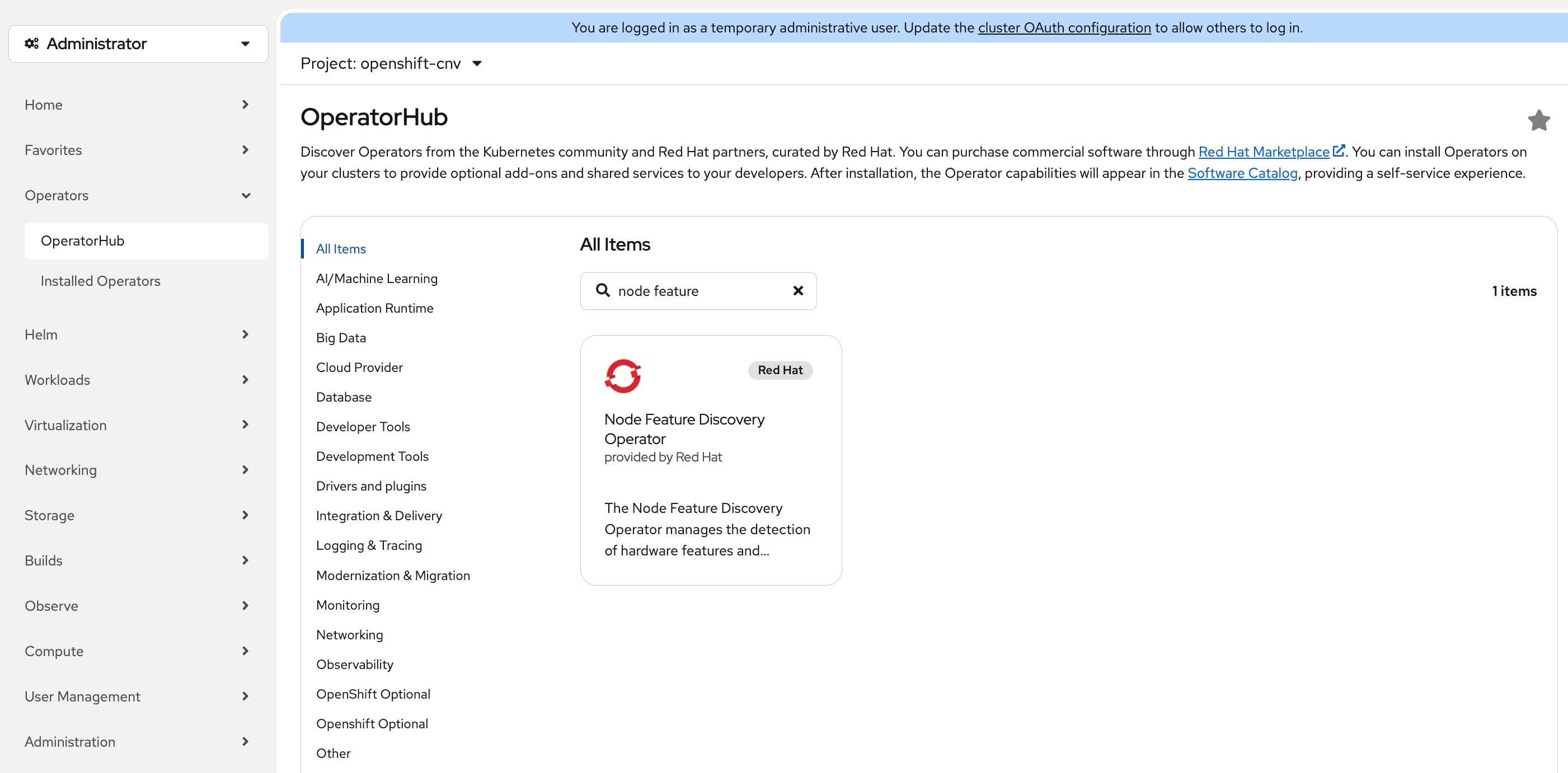
Step 3. On the Node Feature Discovery Operator page, select version 4.19.0-202511260712 and click Install.
Note: This guide uses version 4.19.0-202511260712 which has been validated with OpenShift 4.19.22. If you choose to use a later version, verify compatibility in the Red Hat documentation.
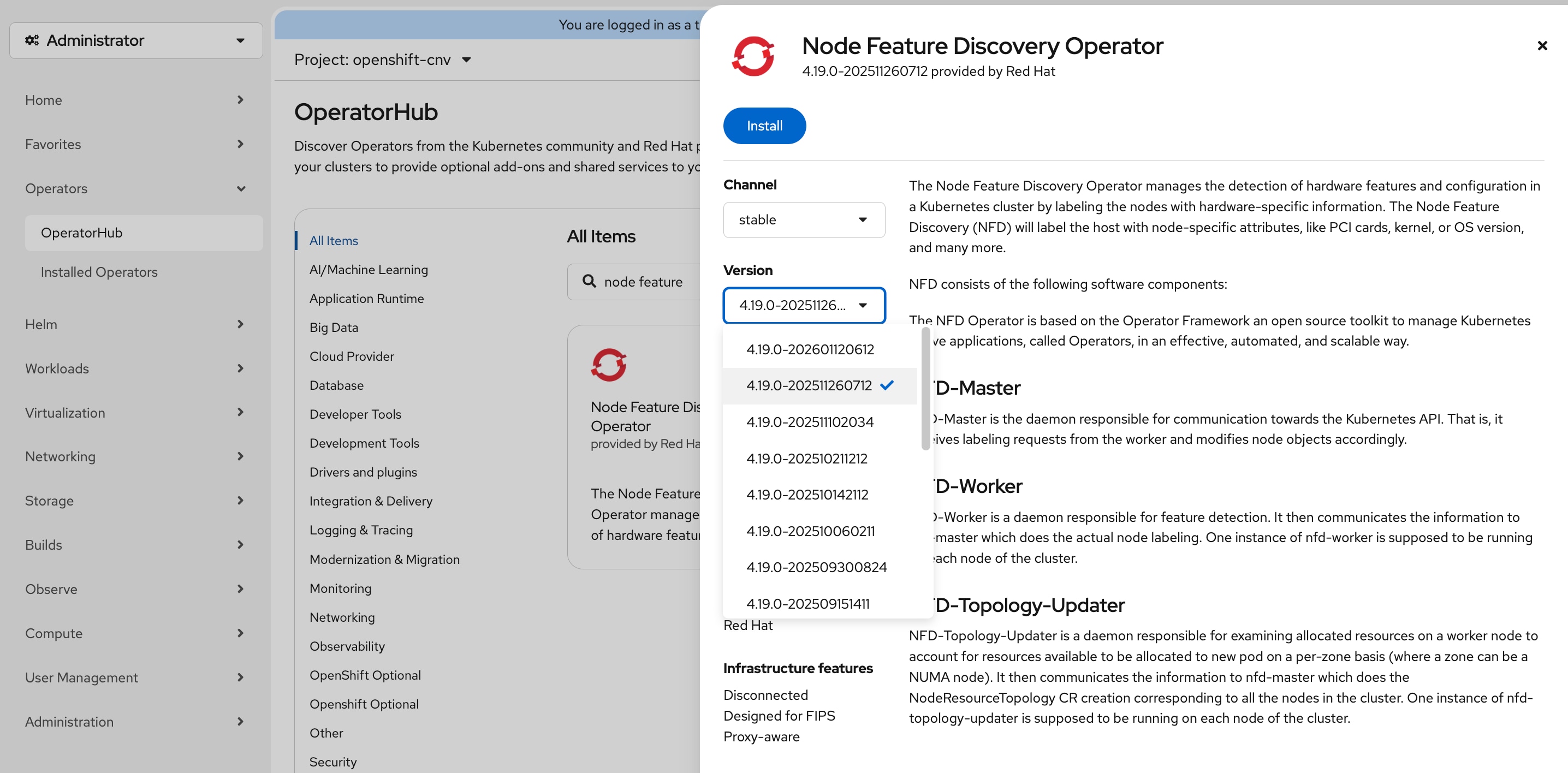
Step 4. On the Install Operator page, do not change any settings and click Install. It may take a few minutes for the installation to complete.
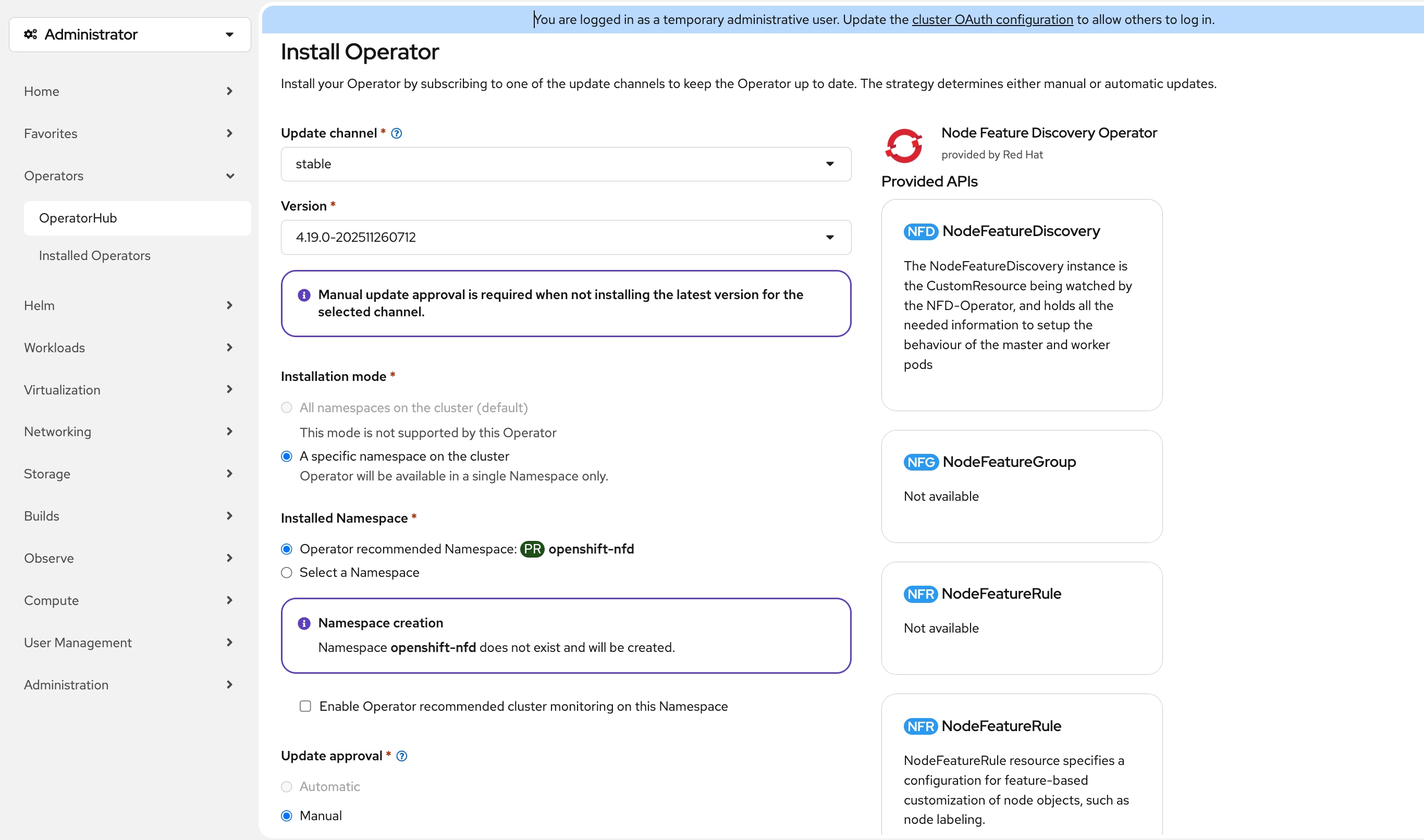
Step 5. Click Approve in the Manual approval required confirmation box.
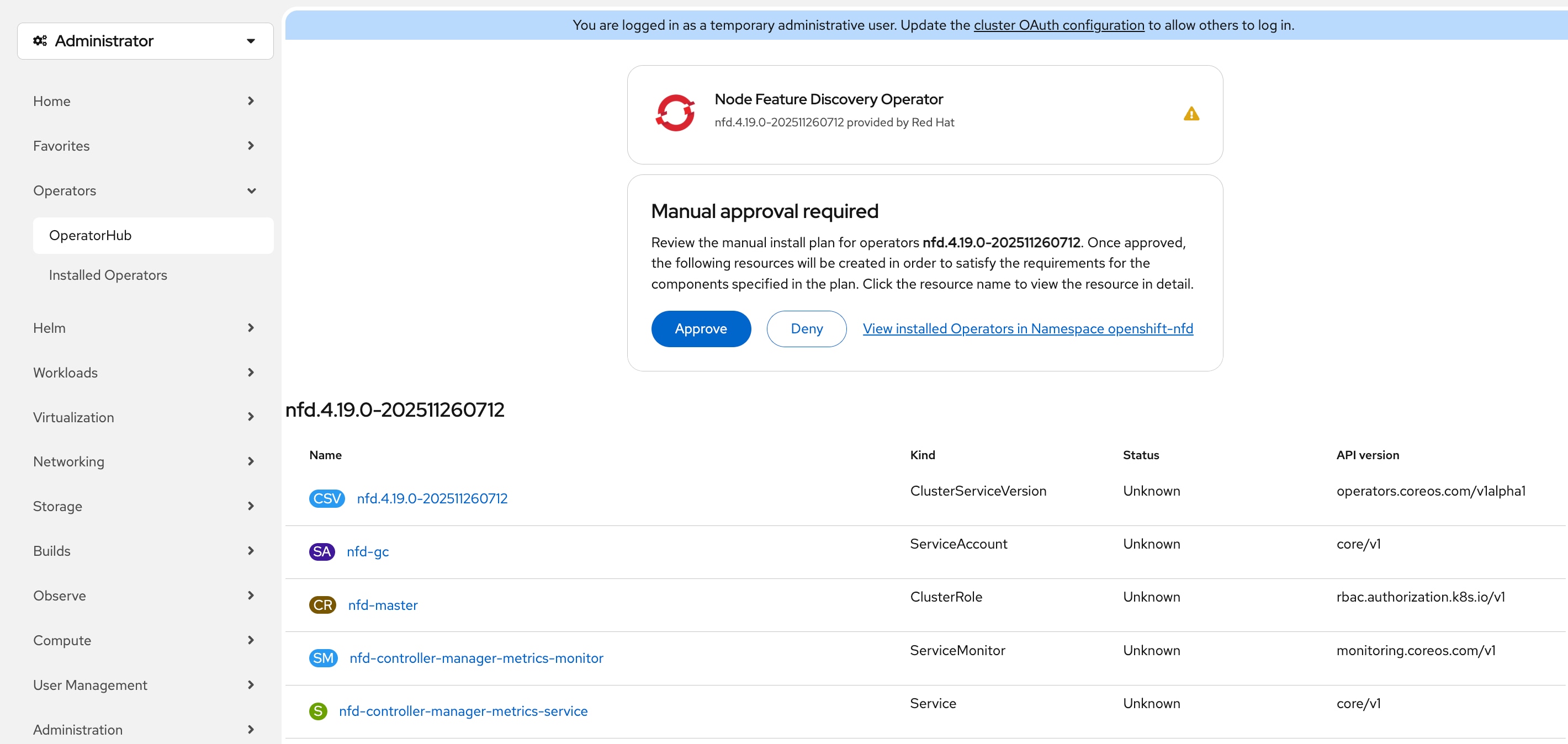
Step 6. In the OpenShift web console, go to Operators > Installed Operators, verify the status of Node Feature Discovery Operator is Succeeded and then click Node Feature Discovery Operator.
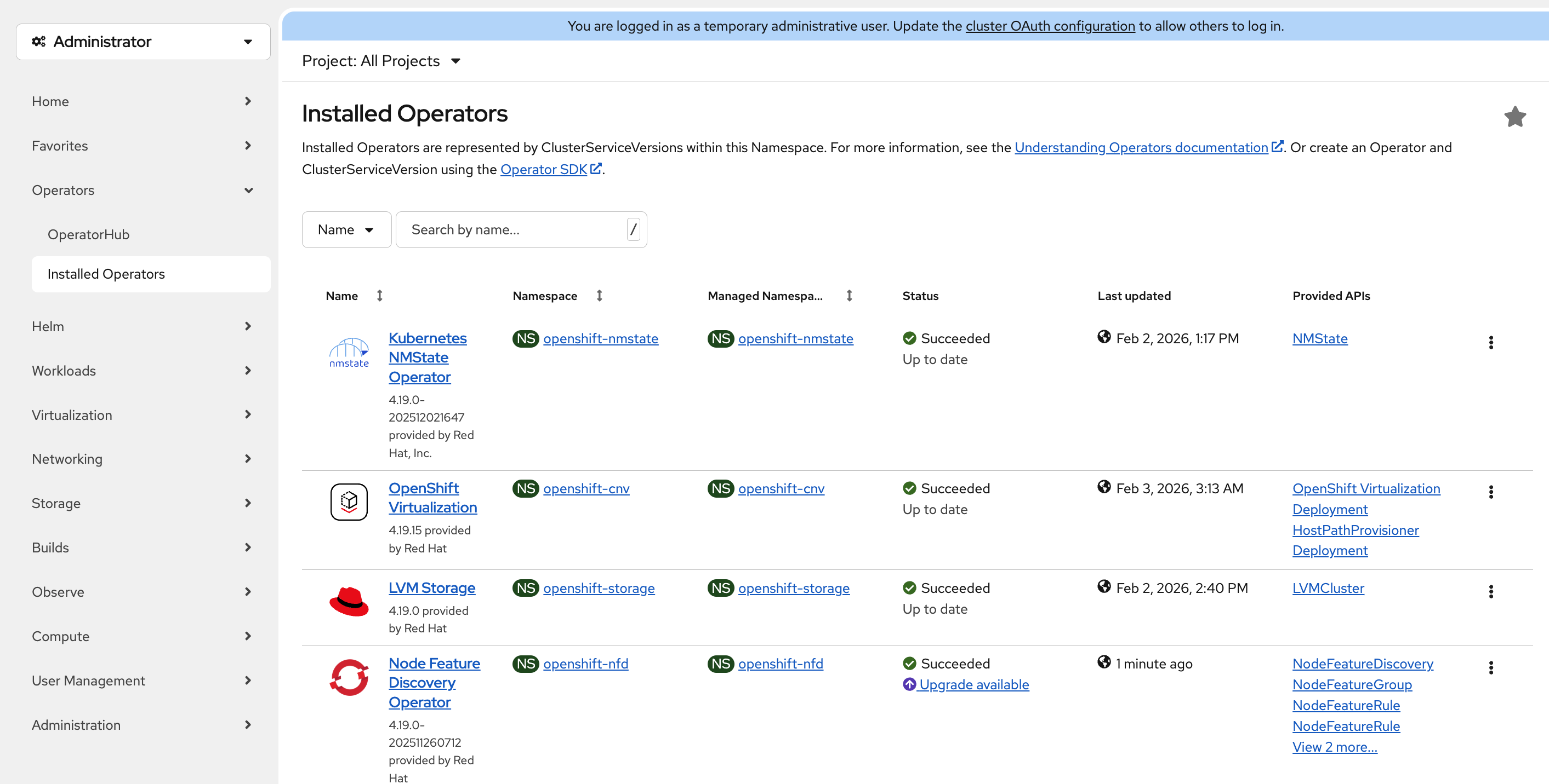
Step 7. On the Operator details page, click the NodeFeatureDiscovery tab, then click Create NodeFeatureDiscovery.
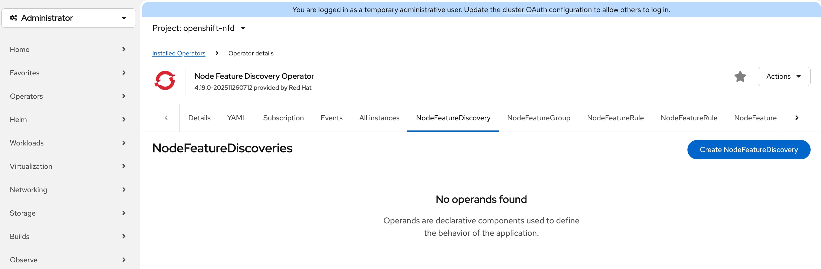
Step 8. On the Create NodeFeatureDiscovery page, leave all settings at their default value, click Create. It may take a few minutes for the nfd-instance to reach the status of Available, Upgradeable.
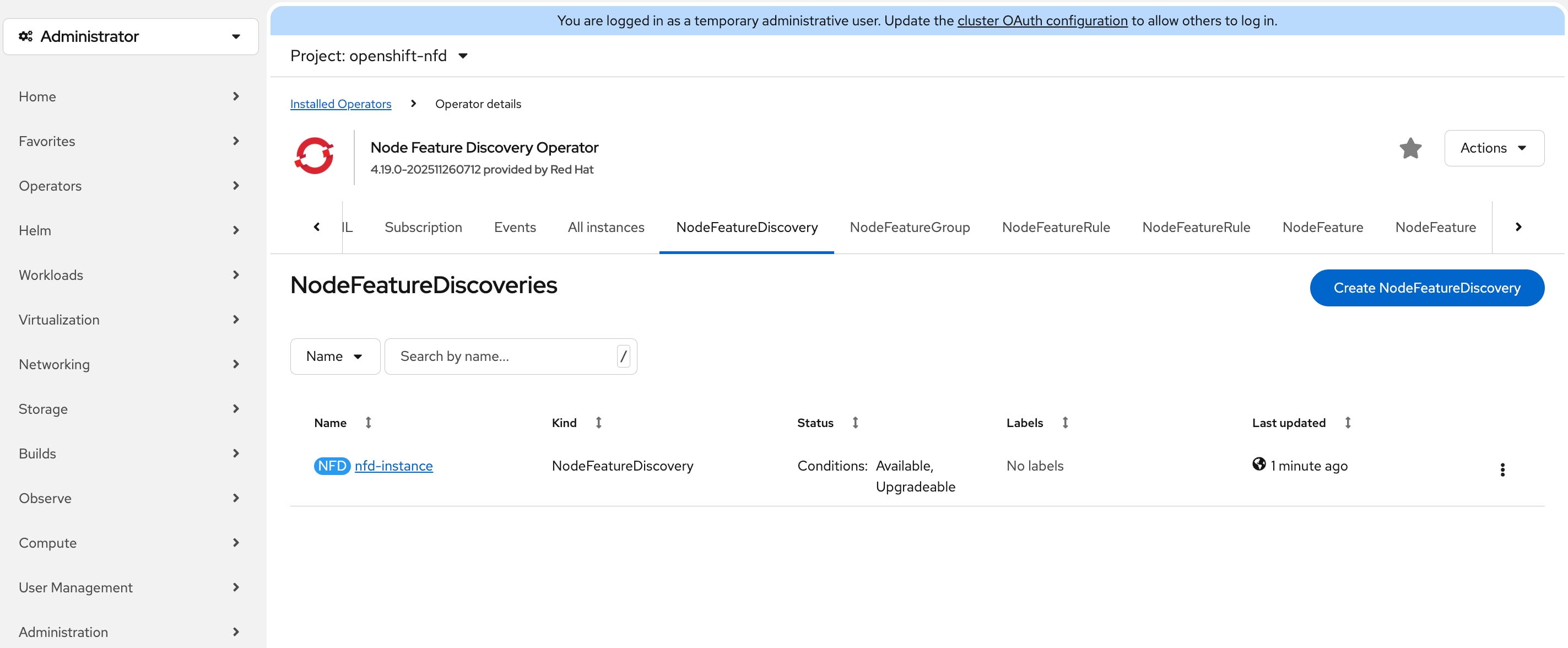
Step 9. Go to Compute > Nodes, click the node that has GPU.
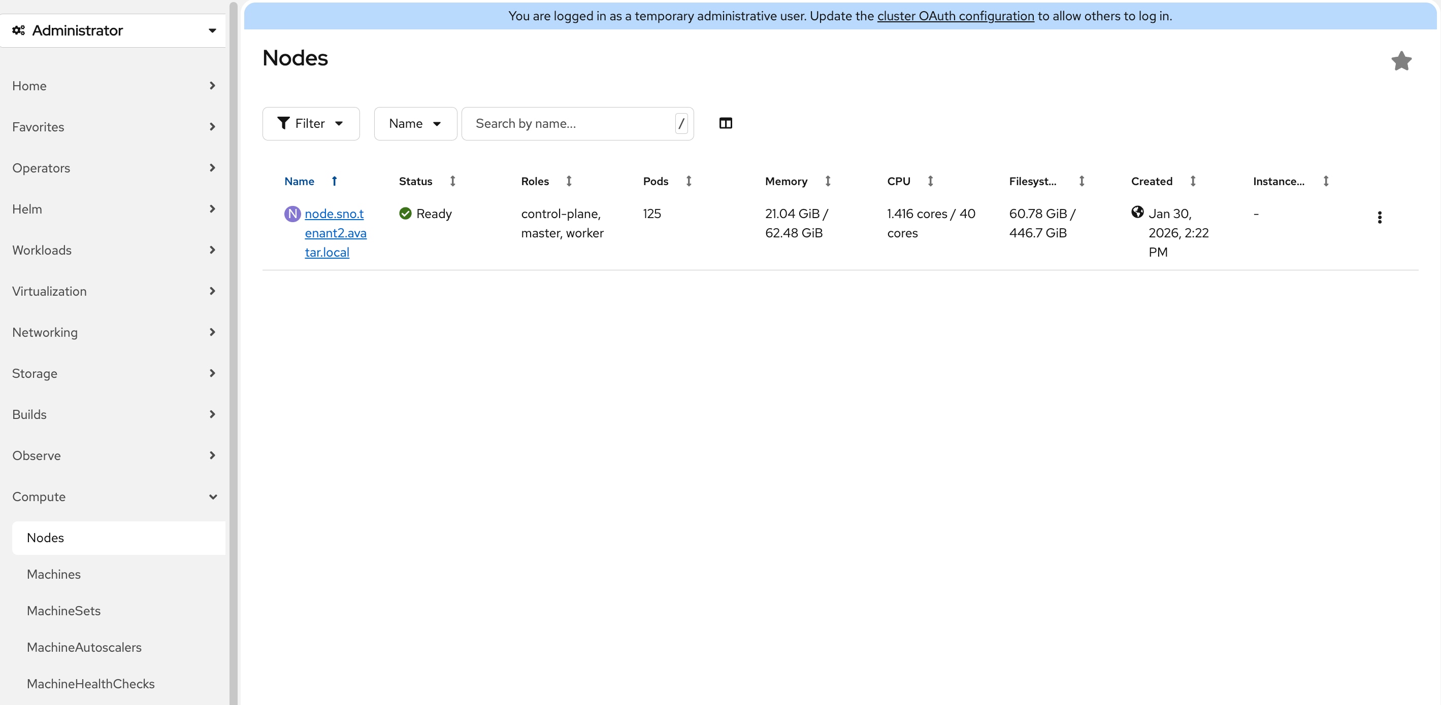
Step 10. On the Node details page, click Details tab.
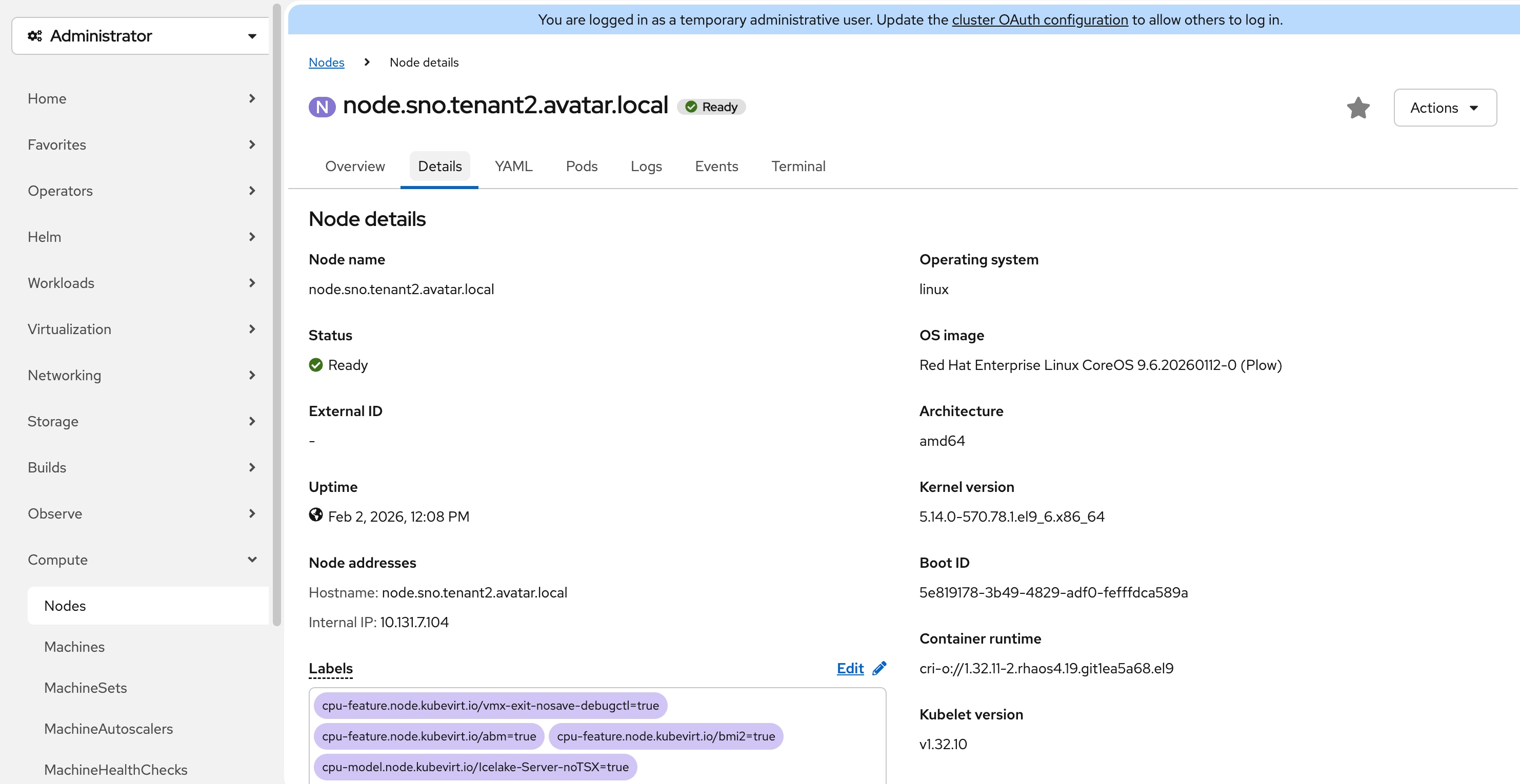
Step 11. In the Labels section, the label feature.node.kubernetes.io/pci-10de.present=true should be present on the host. 0x10de is the PCI vendor ID assigned to NVIDIA.
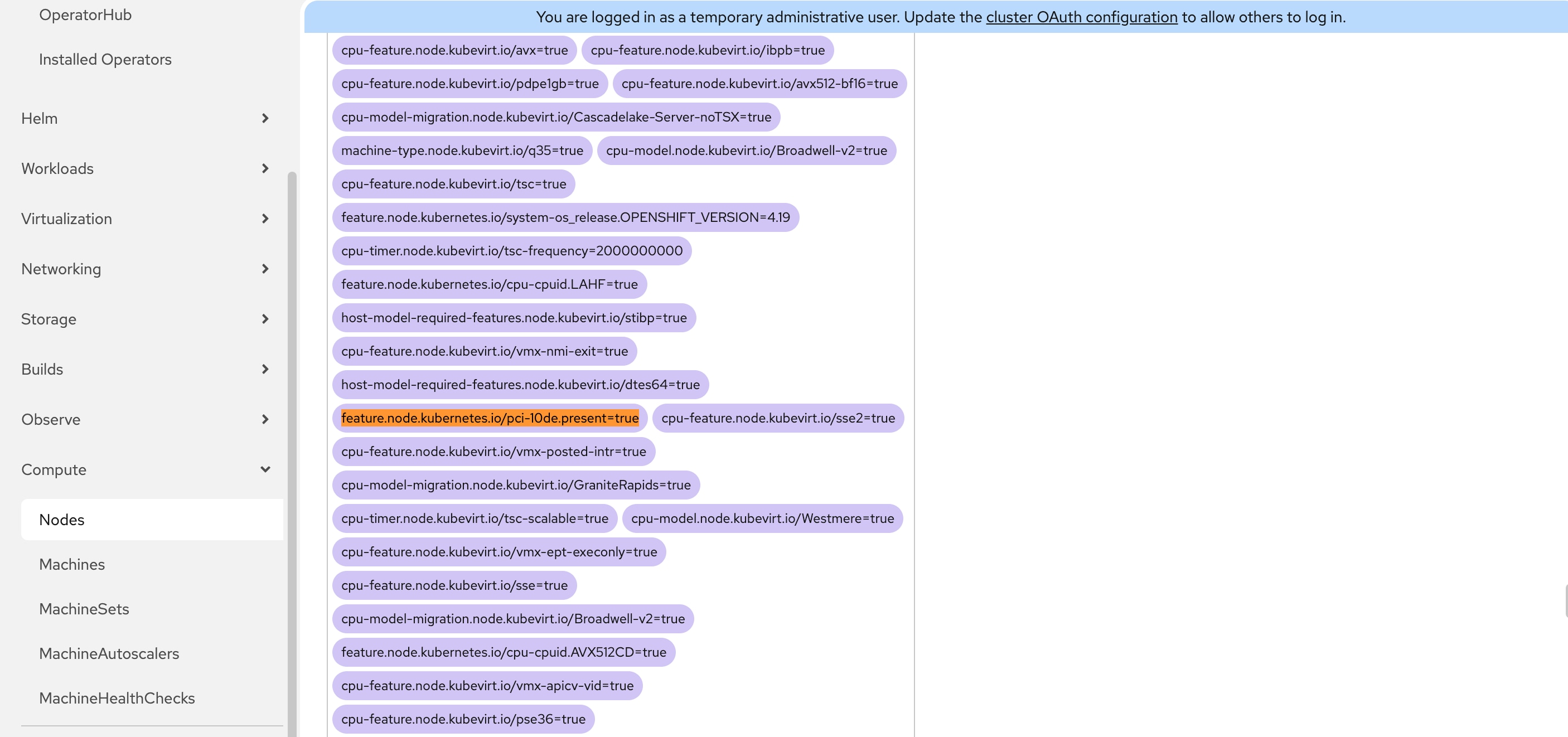
Procedure 6. Install NVIDIA GPU Operator (Required only if NVIDIA L4 GPU is present)
Step 1. In the OpenShift web console, go to Operators > OperatorHub.
Step 2. Type nvidia gpu in the filter box and then click the NVIDIA GPU Operator.
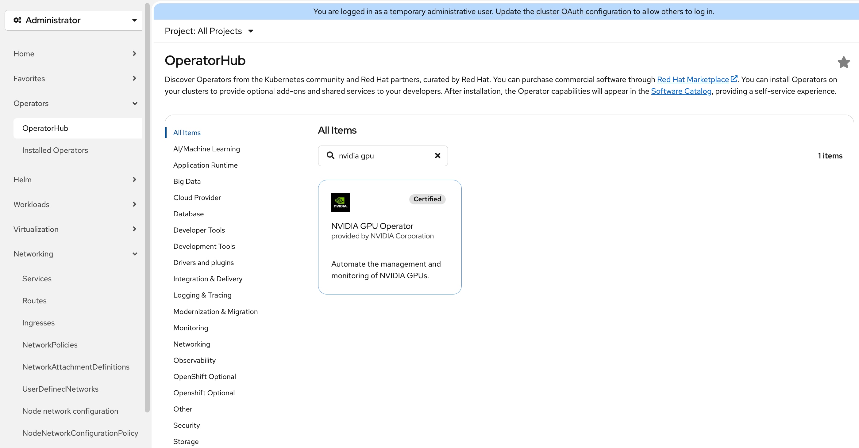
Step 3. On the NVIDIA GPU Operator page, do not change any settings and click Install.
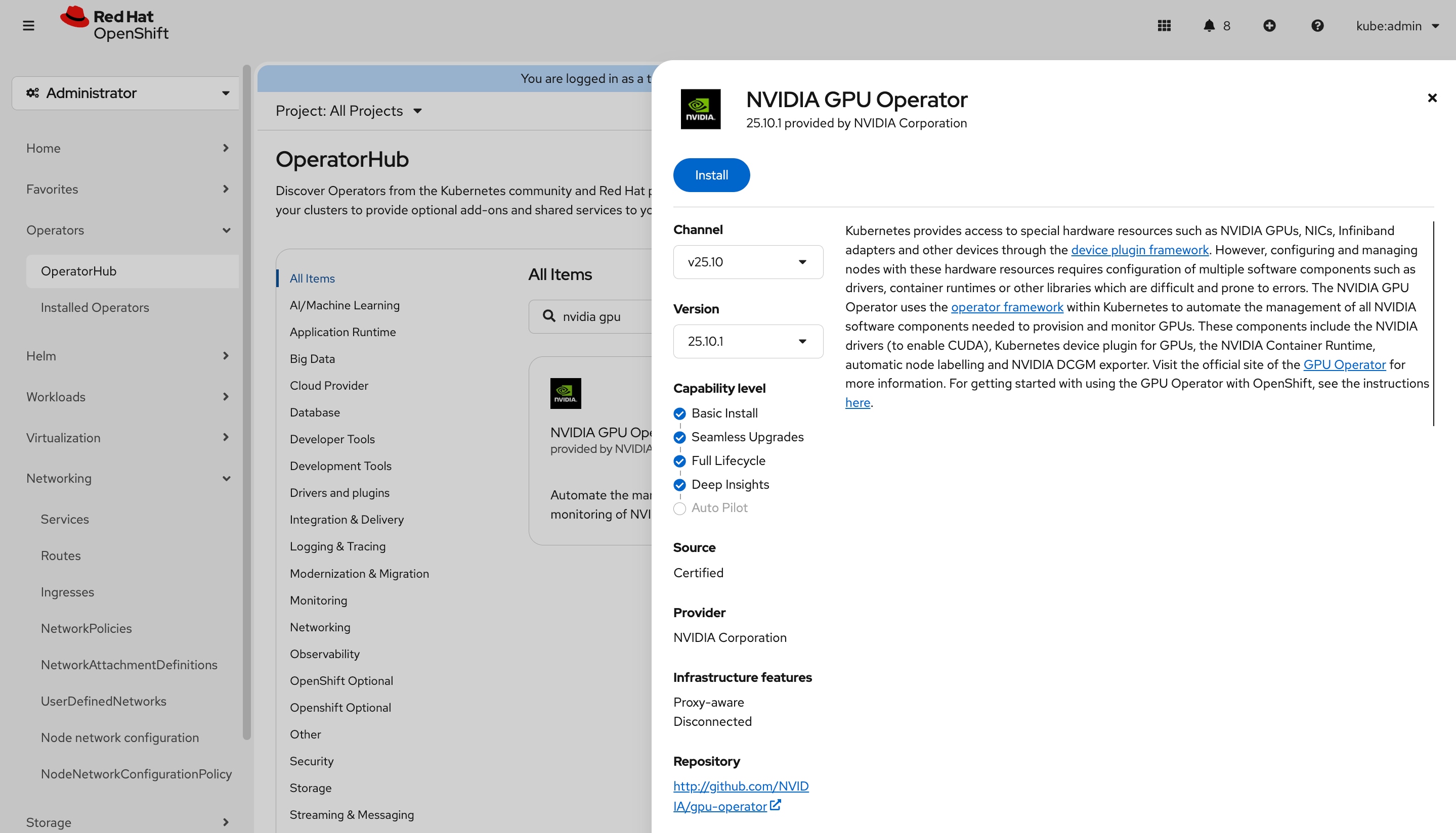
Step 4. On the Install Operator page, leave all settings at their default values and click Install.
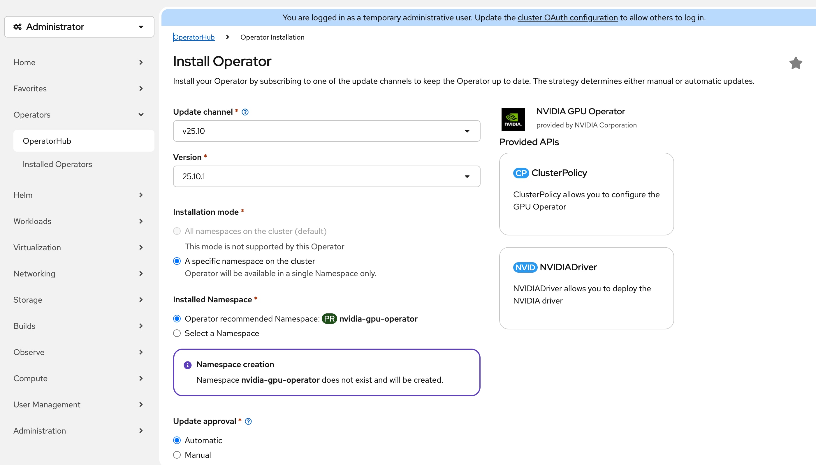
Step 5. Go to Operators > Installed Operators, the status of NVIDIA GPU Operator should be Succeeded. Click NVIDIA GPU Operator.
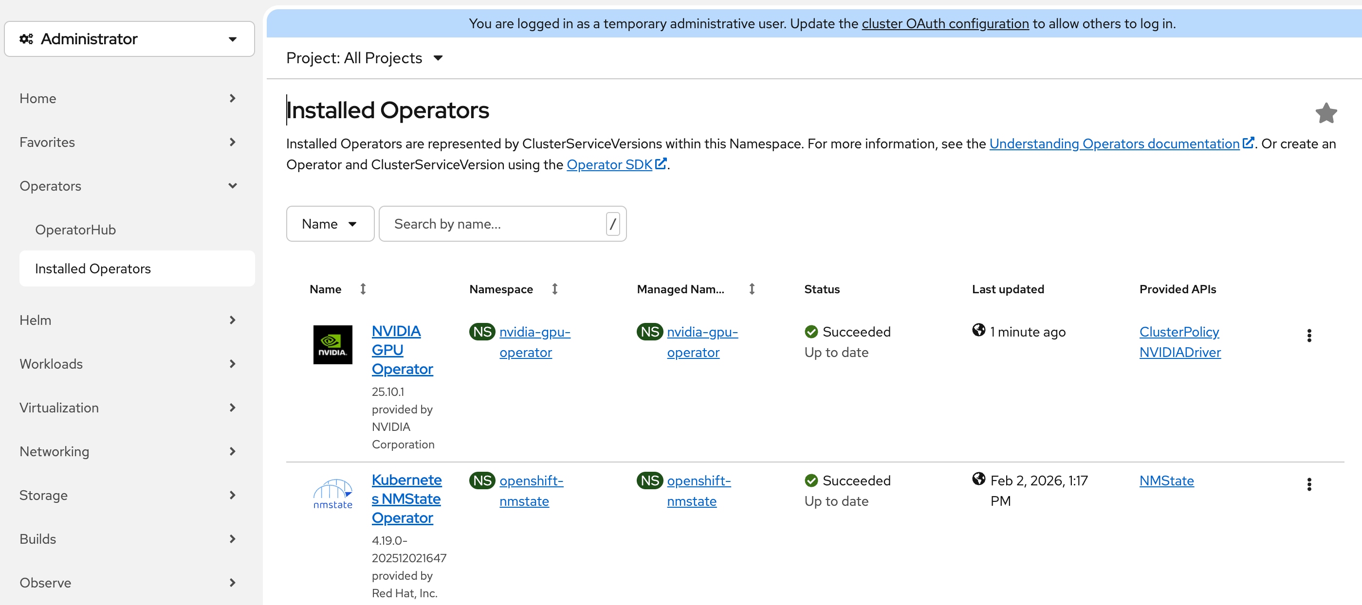
Step 6. On the Operator details page, click the ClusterPolicy tab, then click Create ClusterPolicy.
Step 7. On the Create ClusterPolicy page, leave all settings to their default values and click Create.
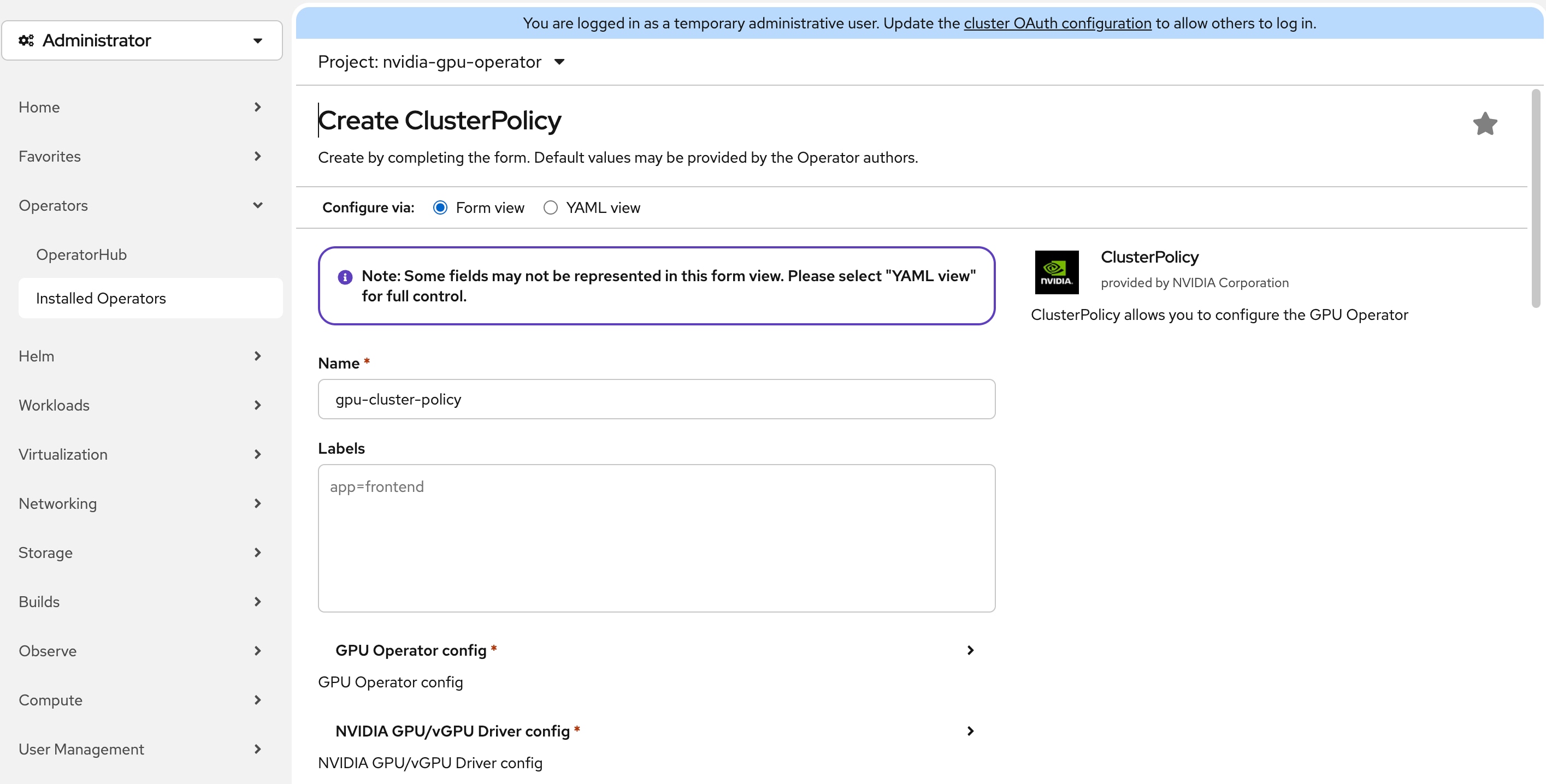
Step 8. Wait for the status of gpu-cluster-policy to become ready. It will take around 10 minutes.
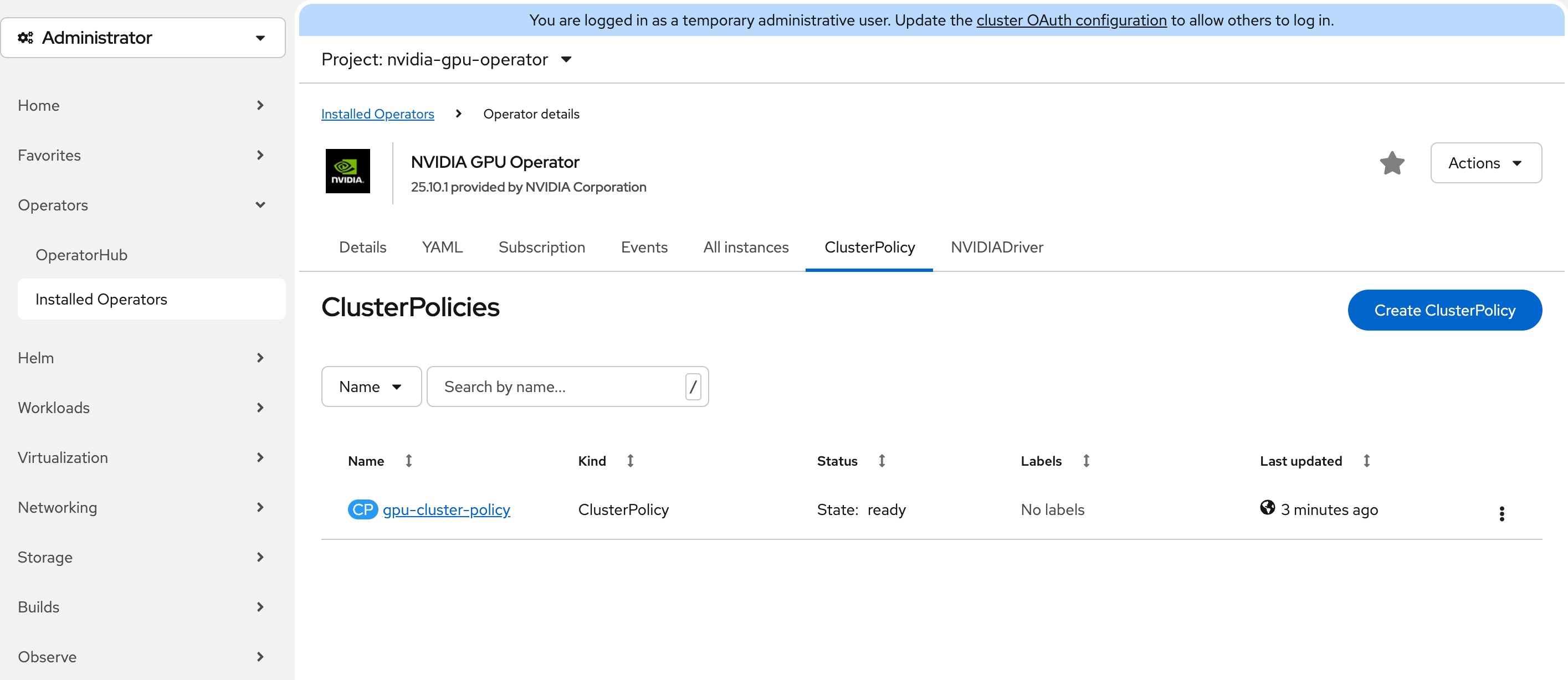
Step 9. Connect to a terminal window on the workstation. Type the following commands:
$ oc -n nvidia-gpu-operator get pods
NAME READY STATUS RESTARTS AGE
gpu-feature-discovery-48qxb 1/1 Running 0 2m30s
gpu-operator-5dfbbc4764-gpzwf 1/1 Running 1 43m
nvidia-container-toolkit-daemonset-k85v4 1/1 Running 0 2m29s
nvidia-cuda-validator-sxfzn 0/1 Completed 0 42s
nvidia-dcgm-exporter-qhglh 1/1 Running 1 (20s ago) 2m29s
nvidia-dcgm-ht4xm 1/1 Running 0 2m30s
nvidia-device-plugin-daemonset-r6ctb 1/1 Running 0 2m30s
nvidia-driver-daemonset-9.6.20260112-0-65v8f 2/2 Running 0 3m6s
nvidia-node-status-exporter-cf2hz 1/1 Running 0 3m3s
nvidia-operator-validator-l7lz6 1/1 Running 0 2m30s
Step 10. Connect to one of the nvidia-driver-daemonset containers. The pod name begins with nvidia-driver-daemonset. Inside the pod, run nvidia-smi command to view the GPU status. You should see NVIDIA L4 GPU is detected.
$ oc -n nvidia-gpu-operator exec -it nvidia-driver-daemonset-9.6.20260112-0-65v8f -- bash
[root@nvidia-driver-daemonset-9 drivers]# nvidia-smi
Tue Feb 3 15:54:23 2026
+-----------------------------------------------------------------------------------------+
| NVIDIA-SMI 580.105.08 Driver Version: 580.105.08 CUDA Version: 13.0 |
+-----------------------------------------+------------------------+----------------------+
| GPU Name Persistence-M | Bus-Id Disp.A | Volatile Uncorr. ECC |
| Fan Temp Perf Pwr:Usage/Cap | Memory-Usage | GPU-Util Compute M. |
| | | MIG M. |
|=========================================+========================+======================|
| 0 NVIDIA L4 On | 00000000:60:00.0 Off | 0 |
| N/A 47C P8 17W / 72W | 0MiB / 23034MiB | 0% Default |
| | | N/A |
+-----------------------------------------+------------------------+----------------------+
+-----------------------------------------------------------------------------------------+
| Processes: |
| GPU GI CI PID Type Process name GPU Memory |
| ID ID Usage |
|=========================================================================================|
| No running processes found |
+-----------------------------------------------------------------------------------------+
Install and Configure SNO Using CLI and YAMLs
This section describes the deployment procedures for installing a Red Hat Single Node OpenShift (SNO) cluster using the Agent-based Installer method. The Agent-based Installer provides a command-line interface (CLI) approach that leverages YAML configuration files for a declarative, automation-friendly deployment process. This method is recommended for users who require programmatic control and the ability to integrate OpenShift deployments into existing automation frameworks.
Note: If you prefer an interactive installation experience with a web-based graphical user interface, see section Install and Configure SNO Using Assisted Installer.
The deployment process begins with the OpenShift Installer to establish your OpenShift SNO cluster, then progressively builds the required infrastructure through operator installations. You'll configure networking capabilities through NMState, establish persistent storage with LVM, and enable virtualization features through the OpenShift Virtualization Operator. Optional VM secondary networks can be configured to support complex networking topologies. For environments with NVIDIA L4 GPU hardware, the guide includes additional configuration steps using the Node Feature Discovery and NVIDIA GPU Operators to unlock GPU-accelerated computing capabilities for your virtual machines.
Installation Flow:
● Deploy base OpenShift cluster via OpenShift Installer
● Enable infrastructure operators: NMState, LVM Storage, OpenShift Virtualization
● Configure optional VM secondary networks (if required)
● Enable GPU support: Node Feature Discovery Operator + NVIDIA GPU Operator (L4 GPU systems)
Prerequisites
DNS Entries
The following domain and OpenShift cluster names are used in this deployment guide:
● Base Domain: tenant2.avatar.local
● OpenShift Cluster Name: sno
The DNS domain name for the OpenShift cluster should be the cluster name followed by the base domain, for example, sno.tenant2.avatar.local.
Prior to initiating the OpenShift installation, the following DNS entries must be configured on your DNS server.
Table 6. DNS FQDN Names Used in OCP SNO Cluster
| DNS Name |
IP Address |
Note |
| api.sno.tenant2.avatar.local |
10.131.7.104 |
Points to the API server endpoint IP address, used for cluster management and API access |
| *.apps.sno.tenant2.avatar.local |
10.131.7.104 |
Wildcard entry pointing to the Ingress/Router IP address, enabling access to all applications and routes deployed on the cluster |
| node.sno.tenant2.avatar.local |
10.131.7.104 |
Points to the node IP address(es) for Single Node OpenShift (SNO) deployment |
Reverse DNS entries for all IP addresses used by the cluster nodes, API endpoints, and ingress controllers must also be configured to map back to their respective hostnames. This ensures proper hostname resolution during installation and is required for various OpenShift components to function correctly.
SSH Key
Before proceeding with the OpenShift installation using the Agent-based Installer, you must generate an SSH key pair on your local machine or workstation. The SSH key pair consists of a private key (which you retain securely) and a public key (which will be embedded into the bootable agent ISO image during the cluster configuration process).
oc CLI
Follow the instruction in Red Hat documentation to install oc cli tool on the workstation: https://docs.redhat.com/en/documentation/openshift_container_platform/4.19/html/cli_tools/openshift-cli-oc
openshift-install CLI
Follow the instruction in Red Hat documentation to install openshift-install cli tool on the workstation: https://docs.redhat.com/en/documentation/openshift_container_platform/4.19/html-single/installing_an_on-premise_cluster_with_the_agent-based_installer/index#installing-ocp-agent-retrieve_installing-with-agent-basic
OpenShift Pull secret
The OpenShift pull secret can be downloaded by using the following link: https://console.redhat.com/openshift/install/pull-secret
Procedure 1. Obtain MAC addresses
Obtain the MAC addresses of the two interfaces from the UCS Server Profile for the OpenShift node. The MAC addresses will be used in the static IP address binding to assign reserved IP addresses to the node.
Step 1. Log into Cisco Intersight.
Step 2. Go to Operate > Servers, click the server you want to install OpenShift.
Step 3. Click the Inventory tab, go to Network Adapters > Adapter LOM-NIC-1, then click the Interfaces.
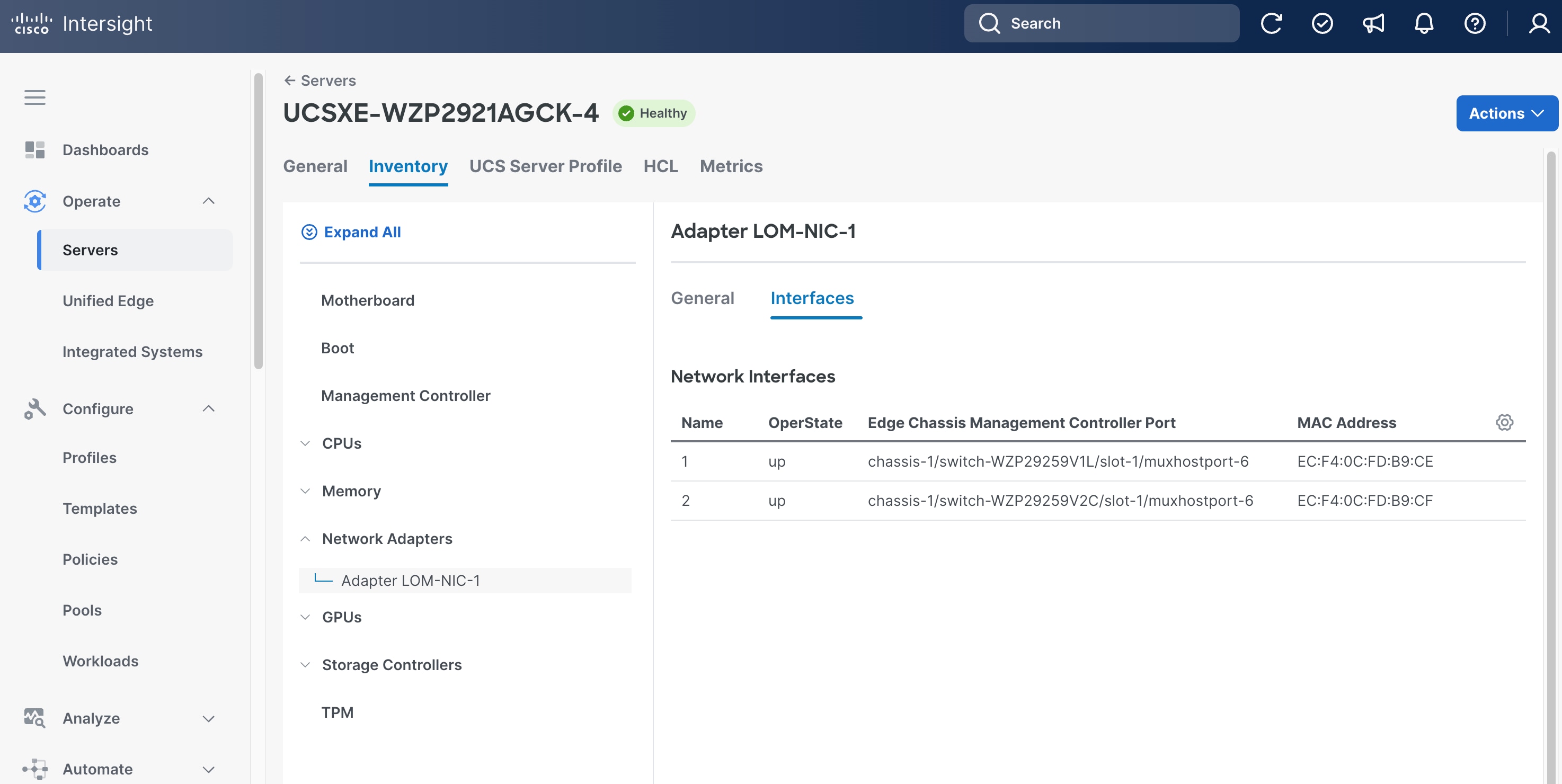
Step 4. Write down the MAC addresses for network interface 1, which is associated with chassis-1/switch-WZP29259V1L/slot-1/muxhostport-6, and network interface 2, which is associated with chassis-1/switch-WZP29259V2C/slot-1/muxhostport-6. These values will be used to create static IP assignment.
● Network Interface 1 MAC =
● Network Interface 2 MAC =
Note: The chassis and switch identifiers shown in the interface associations (for example, chassis-1/switch-WZP29259V1L/slot-1/muxhostport-6) are examples from this deployment and will differ in your environment.
Install OpenShift 4.19 SNO Cluster Using Agent-Based Installer
The Agent-based installer uses two primary files to define the cluster's identity and node-specific network settings. The install-config.yaml specifies the cluster name, base domain, and the virtual IPs for API and Ingress access. The agent-config.yaml maps physical MAC addresses to static IP addresses and configures the network bond and VLAN tagging for the node. This method allows for declarative configuration of complex network settings before the cluster installation begins. When generated, these files are used to create a bootable discovery ISO.
Procedure 1. Install OpenShift 4.19 SNO cluster using Agent-based installer
Step 1. Create installation directory:
mkdir -p ~/sno-cluster
cd ~/sno-cluster
Step 2. Create install-config.yaml file in the installation directory:
File install-config.yaml
apiVersion: v1
baseDomain: tenant2.avatar.local
compute:
- name: worker
replicas: 0
controlPlane:
name: master
replicas: 1
metadata:
name: sno
networking:
clusterNetwork:
- cidr: 10.124.0.0/14
hostPrefix: 23
machineNetwork:
- cidr: 10.131.7.0/24
networkType: OVNKubernetes
serviceNetwork:
- 172.30.0.0/16
platform:
none: {}
bootstrapInPlace:
installationDisk: /dev/sda
pullSecret: '<YOUR_PULL_SECRET_HERE>'
sshKey: '<YOUR_SSH_PUBLIC_KEY_HERE>'
Note: The installation disk is set to /dev/sda, which corresponds to the M.2 RAID volume on the Cisco UCS XE130c M8 node. The NVMe drive (/dev/nvme0n1) is intentionally left unpartitioned during OS installation so that it is presented as a raw disk to the LVM Storage Operator in a later step. Do not modify the NVMe drive or assign it a filesystem during installation.
Step 3. Create agent-config.yaml based on the following template.
Before creating the YAML configuration, gather the following information:
●
●
●
●
●
apiVersion: v1alpha1
kind: AgentConfig
metadata:
name: sno
rendezvousIP: <NODE-IP>
hosts:
- hostname: node.sno.tenant2.avatar.local
role: master
interfaces:
- name: eno1
type: ethernet
state: up
mtu: 9000
mac-address: <NODE-NIC1-MAC>
ipv4:
enabled: false
- name: eno2
type: ethernet
state: up
mtu: 9000
mac-address: <NODE-NIC2-MAC>
ipv4:
enabled: false
- name: bond0
type: bond
state: up
mtu: 9000
link-aggregation:
mode: active-backup
options:
primary: eno1
miimon: "100"
primary_reselect: always
port:
- eno1
- eno2
ipv4:
enabled: false
ipv6:
enabled: false
- name: bond0.<ACCESS-VLAN-ID>
type: vlan
state: up
mtu: 1500
vlan:
base-iface: bond0
id: <ACCESS-VLAN-ID>
ipv4:
address:
- ip: <NODE-IP>
prefix-length: <NODE-SUBNET-MASK-LENGTH>
dhcp: false
enabled: true
ipv6:
enabled: false
routes:
config:
- destination: 0.0.0.0/0
next-hop-address: <ACCESS-NETWORK-DEFAULT-GATEWAY>
next-hop-interface: bond0.<ACCESS-VLAN-ID>
table-id: 254
dns-resolver:
config:
server:
- <DNS-SERVER-IP>
File agent-config.yaml
apiVersion: v1alpha1
kind: AgentConfig
metadata:
name: sno
rendezvousIP: 10.131.7.104
additionalNTPSources:
- 10.81.254.202
hosts:
- hostname: node.sno.tenant2.avatar.local
role: master
interfaces:
- name: eno1
macAddress: EC:F4:0C:FD:B9:CE
- name: eno2
macAddress: EC:F4:0C:FD:B9:CF
networkConfig:
interfaces:
- name: eno1
type: ethernet
state: up
mtu: 9000
mac-address: EC:F4:0C:FD:B9:CE
ipv4:
enabled: false
- name: eno2
type: ethernet
state: up
mtu: 9000
mac-address: EC:F4:0C:FD:B9:CF
ipv4:
enabled: false
- name: bond0
type: bond
state: up
mtu: 9000
link-aggregation:
mode: active-backup
options:
primary: eno1
miimon: "100"
primary_reselect: always
port:
- eno1
- eno2
ipv4:
enabled: false
ipv6:
enabled: false
- name: bond0.1317
type: vlan
state: up
mtu: 1500
vlan:
base-iface: bond0
id: 1317
ipv4:
address:
- ip: 10.131.7.104
prefix-length: 24
dhcp: false
enabled: true
ipv6:
enabled: false
routes:
config:
- destination: 0.0.0.0/0
next-hop-address: 10.131.7.1
next-hop-interface: bond0.1317
table-id: 254
dns-resolver:
config:
server:
- 10.140.1.101
Step 4. Install nmstatectl:
The agent-config.yaml contains static network configuration for the host with specific network interfaces (eno1, eno2). The installer needs to validate these NMState configurations using the nmstatectl tool. The following command shows how to install nmstatectl on RHEL 9.6.
sudo dnf install nmstate
Step 5. Generate the OCP SNO ISO:
openshift-install agent create image --log-level=info
This creates an agent.x86_64.iso file in the working directory.
Step 6. Boot the server from the agent.x86_64.iso image and monitor the installation:
# Wait for installation to complete
openshift-install agent wait-for install-complete --log-level=info
Here is the sample output:
…
INFO Cluster is installed
INFO Install complete!
…
INFO Access the OpenShift web-console here: https://console-openshift-console.apps.sno.tenant2.avatar.local
INFO Login to the console with user: "kubeadmin", and password: "<YOUR-PASSWORD-HERE>"
Step 7. After installation is complete, download the kubeconfig from OpenShift Console:
export KUBECONFIG=~/sno-cluster/auth/kubeconfig
oc get nodes
The node should be in Ready status as shown in the example below:
NAME STATUS ROLES AGE VERSION
node.sno.tenant2.avatar.local Ready control-plane,master,worker 31m v1.32.10
Install NMState Operator and Create NMState Instance
The Kubernetes NMState Operator provides declarative network configuration for OpenShift nodes, enabling dynamic management of complex networking scenarios. It allows you to configure network interfaces, bonds, bridges, and VLANs through Kubernetes custom resources. This operator is essential for managing network configurations in virtualized environments and ensuring consistent networking on the node.
Procedure 1. Install NMStat operator and create an NMState instance
Step 1. Create Namespace, Subscription and OperatorGroup:
File: nmstate.yaml
apiVersion: v1
kind: Namespace
metadata:
name: openshift-nmstate
spec:
finalizers:
- kubernetes
---
apiVersion: operators.coreos.com/v1
kind: OperatorGroup
metadata:
name: openshift-nmstate
namespace: openshift-nmstate
spec:
targetNamespaces:
- openshift-nmstate
---
apiVersion: operators.coreos.com/v1alpha1
kind: Subscription
metadata:
name: kubernetes-nmstate-operator
namespace: openshift-nmstate
spec:
channel: stable
installPlanApproval: Manual
name: kubernetes-nmstate-operator
source: redhat-operators
sourceNamespace: openshift-marketplace
startingCSV: kubernetes-nmstate-operator.4.19.0-202512021647
Step 2. Apply the YAML file:
oc apply -f nmstate.yaml
Step 3. Approve the install plan:
# Get the install plan name
INSTALL_PLAN=$(oc get installplan -n openshift-nmstate -o jsonpath='{.items[0].metadata.name}')
# Approve the install plan
oc patch installplan $INSTALL_PLAN -n openshift-nmstate --type merge --patch '{"spec":{"approved":true}}'
Step 4. Check the CSV status:
oc get csv -n openshift-nmstate
The PHASE of the CSV should be Succeeded as shown in the sample output below:
NAME DISPLAY VERSION REPLACES PHASE
kubernetes-nmstate-operator.4.19.0-202512021647 Kubernetes NMState Operator 4.19.0-202512021647 Succeeded
Step 5. Prepare NMState Operator yaml file:
File: nmstate-instance.yaml
apiVersion: nmstate.io/v1
kind: NMState
metadata:
name: nmstate
spec: {}
Step 6. Create the NMState Operator:
oc apply -f nmstate-instance.yaml
Step 7. Verify NMState operator status:
oc get pods -n openshift-nmstate
All pods should be in Running status as shown in the sample output below:
NAME READY STATUS RESTARTS AGE
nmstate-console-plugin-654687f6f8-4pmgn 1/1 Running 4 17d
nmstate-handler-dx6qk 1/1 Running 4 17d
nmstate-metrics-6bfb9b4648-pz5dx 2/2 Running 8 17d
nmstate-operator-c55fb576-2zh46 1/1 Running 4 17d
nmstate-webhook-8688bd4968-2zc89 1/1 Running 4 17d
Install LVM Storage Operator and Create LVMCluster Instance
The LVM Storage Operator (LVMS) provides dynamic local storage provisioning using Logical Volume Manager technology for OpenShift clusters. It creates a storage class that automatically provisions persistent volumes from local NVMe or SSD devices, making it ideal for edge and single-node deployments. This operator eliminates the need for external storage arrays while providing thin provisioning and efficient storage utilization.
Procedure 1. Install LVM storage operator and create an LVMCluster instance
Step 1. Prepare the lvm-operator.yaml file:
File: lvm-operator.yaml
apiVersion: v1
kind: Namespace
metadata:
labels:
openshift.io/cluster-monitoring: "true"
pod-security.kubernetes.io/enforce: privileged
pod-security.kubernetes.io/audit: privileged
pod-security.kubernetes.io/warn: privileged
name: openshift-storage
---
apiVersion: operators.coreos.com/v1
kind: OperatorGroup
metadata:
name: openshift-storage
namespace: openshift-storage
spec:
targetNamespaces:
- openshift-storage
---
apiVersion: operators.coreos.com/v1alpha1
kind: Subscription
metadata:
labels:
operators.coreos.com/lvms-operator.openshift-storage: ""
name: lvms-operator
namespace: openshift-storage
spec:
channel: stable-4.19
installPlanApproval: Manual
name: lvms-operator
source: redhat-operators
sourceNamespace: openshift-marketplace
startingCSV: lvms-operator.v4.19.0
Step 2. Create the Namespace, Subscription and OperatorGroup:
oc apply -f lvm-operator.yaml
Step 3. Approve the install plan:
# Get the install plan name
INSTALL_PLAN=$(oc get installplan -n openshift-storage -o jsonpath='{.items[?(@.spec.clusterServiceVersionNames[0]=="lvms-operator.v4.19.0")].metadata.name}')
# Approve the install plan
oc patch installplan $INSTALL_PLAN -n openshift-storage --type merge --patch '{"spec":{"approved":true}}'
Step 4. Verify the CSV status:
oc get csv -n openshift-storage
The PHASE should be Succeeded as shown in the sample output below:
NAME DISPLAY VERSION REPLACES PHASE
lvms-operator.v4.19.0 LVM Storage 4.19.0 Succeeded
Step 5. Prepare the LVMCluster yaml file:
File: lvmcluster-instance.yaml
apiVersion: lvm.topolvm.io/v1alpha1
kind: LVMCluster
metadata:
name: my-lvmcluster
namespace: openshift-storage
spec:
storage:
deviceClasses:
- default: true
deviceSelector:
paths:
- /dev/nvme0n1
fstype: xfs
name: vg1
thinPoolConfig:
chunkSizeCalculationPolicy: Static
metadataSizeCalculationPolicy: Host
name: thin-pool-1
overprovisionRatio: 10
sizePercent: 90
Step 6. Apply the YAML file:
oc apply -f lvmcluster-instance.yaml
Step 7. Verify LVMCluster and StorageClass:
oc get lvmcluster -n openshift-storage
The status should be Ready as shown in the sample output below:
NAME STATUS
my-lvmcluster Ready
All Pods should be in Running status as shown in the sample output below:
NAME READY STATUS RESTARTS AGE
lvms-operator-5cbf4c87cd-s8x6r 1/1 Running 4 17d
vg-manager-js84r 1/1 Running 4 16d
There should be a storageclass called lvms-vg1 and it is marked as default storageclass:
NAME PROVISIONER RECLAIMPOLICY VOLUMEBINDINGMODE ALLOWVOLUMEEXPANSION AGE
lvms-vg1 (default) topolvm.io Delete WaitForFirstConsumer true 16h
Install OpenShift Virtualization and HyperConverged Instance
OpenShift Virtualization enables running virtual machines alongside containerized workloads on the same OpenShift infrastructure. It leverages KubeVirt technology to provide VM lifecycle management, live migration, and integration with Kubernetes networking and storage. The HyperConverged custom resource orchestrates the deployment of all required virtualization components in a single, cohesive configuration. The installation is performed within the openshift-cnv namespace.
Procedure 1. Install OpenShift virtualization and HyperConverged instance
Step 1. Prepare the virtualization-operator-subscription.yaml file:
File: virtualization-operator.yaml
apiVersion: v1
kind: Namespace
metadata:
name: openshift-cnv
labels:
openshift.io/cluster-monitoring: "true"
---
apiVersion: operators.coreos.com/v1
kind: OperatorGroup
metadata:
name: kubevirt-hyperconverged-group
namespace: openshift-cnv
spec:
targetNamespaces:
- openshift-cnv
---
apiVersion: operators.coreos.com/v1alpha1
kind: Subscription
metadata:
name: kubevirt-hyperconverged
namespace: openshift-cnv
spec:
channel: stable
installPlanApproval: Automatic
name: kubevirt-hyperconverged
source: redhat-operators
sourceNamespace: openshift-marketplace
Step 2. Create the Namespace, Subscription and OperatorGroup:
oc apply -f virtualization-operator.yaml
Step 3. Check the CSV status:
oc get csv -n openshift-cnv
The PHASE should be Succeeded as shown in the sample output below:
NAME DISPLAY VERSION REPLACES PHASE
kubevirt-hyperconverged-operator.v4.19.15 OpenShift Virtualization 4.19.15 kubevirt-hyperconverged-operator.v4.18.28 Succeeded
Step 4. Prepare the HyperConverged instance yaml file:
File: hyperconverged-instance.yaml
apiVersion: hco.kubevirt.io/v1beta1
kind: HyperConverged
metadata:
name: kubevirt-hyperconverged
namespace: openshift-cnv
spec:
Step 5. Create a HyperConverged instance:
oc apply -f hyperconverged-instance.yaml
Step 6. Check OpenShift Virtualization Operator installation:
oc get pods -n openshift-cnv
All pods should be in Running status as shown in the sample output below:
NAME READY STATUS RESTARTS AGE
NAME READY STATUS RESTARTS AGE
aaq-operator-54d5f49fd7-dtngj 1/1 Running 5 (9m15s ago) 4h43m
bridge-marker-5zg4m 1/1 Running 0 2m37s
cdi-apiserver-6b55577764-nfp69 1/1 Running 0 2m36s
cdi-deployment-f65557687-2vjzc 1/1 Running 0 2m36s
cdi-operator-664b865b5d-2gsqm 1/1 Running 6 (9m21s ago) 4h43m
cdi-uploadproxy-db9569dc4-kx4pm 1/1 Running 0 2m35s
cluster-network-addons-operator-85d4ff69b4-bcqkd 2/2 Running 0 4h43m
hco-operator-754d876648-69htf 1/1 Running 7 (9m15s ago) 4h44m
hco-webhook-7b86cf88df-zthzj 1/1 Running 8 (9m16s ago) 4h44m
hostpath-provisioner-operator-79d87bc57c-pg52x 1/1 Running 2 (9m36s ago) 4h43m
hyperconverged-cluster-cli-download-7d7cfccf86-btfmm 1/1 Running 0 4h44m
kube-cni-linux-bridge-plugin-l25sv 1/1 Running 0 2m37s
kubemacpool-cert-manager-586d48b58d-6zh7q 1/1 Running 0 2m36s
kubemacpool-mac-controller-manager-7684ffd69f-8tww2 2/2 Running 1 (2m8s ago) 2m36s
kubevirt-apiserver-proxy-84fff88b5-wbsd9 1/1 Running 0 79s
kubevirt-console-plugin-6754b5ff47-q6nwk 1/1 Running 0 79s
kubevirt-ipam-controller-manager-58fcbf59d-65tfj 1/1 Running 0 2m36s
kubevirt-ipam-controller-manager-58fcbf59d-j5p84 1/1 Running 0 2m36s
ssp-operator-74f65f9574-rtsmr 1/1 Running 6 (2m22s ago) 4h43m
virt-api-5b96f675f5-wqrs2 1/1 Running 0 2m15s
virt-controller-56759f8bb-mtp9g 1/1 Running 0 105s
virt-exportproxy-67765b77c9-tnqn4 1/1 Running 0 105s
virt-handler-njgj5 1/1 Running 0 105s
virt-operator-76f86fbbb8-pt966 1/1 Running 5 (9m16s ago) 4h43m
virt-operator-76f86fbbb8-t5bfg 1/1 Running 0 4h43m
virt-template-validator-94754679b-6dhn4 1/1 Running 0 79s
Install Node Feature Discovery Operator and NodeFeatureDiscovery Instance
Node Feature Discovery (NFD) is a prerequisite for utilizing hardware acceleration like NVIDIA GPUs. It scans the hardware on each node and applies labels to identify specific PCI devices and capabilities. This guide uses version 4.19.0-202511260712 to ensure it correctly identifies the NVIDIA L4 GPUs available on the UCS-XE130c-M8 nodes. These labels are then used by the GPU operator to target driver installations.
Procedure 1. Install the Node Feature Discovery Operator and NodeFeatureDiscovery instance
Step 1. Prepare the nfd-operator-subscription.yaml file:
File: nfd-operator.yaml
apiVersion: v1
kind: Namespace
metadata:
name: openshift-nfd
labels:
name: openshift-nfd
openshift.io/cluster-monitoring: "true"
---
apiVersion: operators.coreos.com/v1
kind: OperatorGroup
metadata:
name: nfd-operatorgroup
namespace: openshift-nfd
spec:
targetNamespaces:
- openshift-nfd
---
apiVersion: operators.coreos.com/v1alpha1
kind: Subscription
metadata:
name: nfd
namespace: openshift-nfd
spec:
channel: stable
installPlanApproval: Manual
name: nfd
source: redhat-operators
sourceNamespace: openshift-marketplace
startingCSV: nfd.4.19.0-202511260712
Step 2. Create the Namespace, Subscription and OperatorGroup:
oc apply -f nfd-operator.yaml
Step 3. Approve the install plan:
# Get the install plan name
INSTALL_PLAN=$(oc get installplan -n openshift-nfd -o jsonpath='{.items[0].metadata.name}')
# Approve the install plan
oc patch installplan $INSTALL_PLAN -n openshift-nfd --type merge --patch '{"spec":{"approved":true}}'
Step 4. Check the CSV status:
oc get csv -n openshift-nfd
The PHASE should be Succeeded as shown in the sample output below:
NAME DISPLAY VERSION REPLACES PHASE
nfd.4.19.0-202511260712 Node Feature Discovery Operator 4.19.0-202511260712 Succeeded
Step 5. Prepare the NodeFeatureDiscovery Operator yaml file:
File: nfd-instance.yaml
apiVersion: nfd.openshift.io/v1
kind: NodeFeatureDiscovery
metadata:
name: nfd-instance
namespace: openshift-nfd
spec:
operand:
imagePullPolicy: Always
workerConfig:
configData: |
core:
sleepInterval: 60s
sources:
pci:
deviceClassWhitelist:
- "0200"
- "03"
- "12"
deviceLabelFields:
- "vendor"
Step 6. Create the NFD Operator:
oc apply -f nfd-instance.yaml
Step 7. Verify NFD operator status and node labels:
oc get pods -n openshift-nfd
All pod status should be Running as shown in the sample output below:
NAME READY STATUS RESTARTS AGE
nfd-controller-manager-c4ffc6969-rzczq 1/1 Running 0 19m
nfd-gc-74565d5674-55kxs 1/1 Running 0 36s
nfd-master-5758f65c49-cnl6k 1/1 Running 0 36s
nfd-worker-js4nl 1/1 Running 0 36s
Step 8. Verify the node label exists:
oc describe node node.sno.tenant2.avatar.local | grep -i "pci-10de"
The node label feature.node.kubernetes.io/pci-10de.present=true must exist as shown in the sample output below:
feature.node.kubernetes.io/pci-10de.present=true
feature.node.kubernetes.io/pci-10de.sriov.capable=true
Install NVIDIA GPU Operator
The NVIDIA GPU Operator automates the management of all software components needed to expose GPUs to workloads. It uses the labels provided by NFD to install the correct drivers, CUDA libraries, and device plugins. The ClusterPolicy instance is the top-level configuration that manages the lifecycle of these GPU components. This enables high-performance computing and AI/ML workloads to run within virtual machines or containers. For detailed installation procedures, see the official NVIDIA documentation: https://docs.nvidia.com/datacenter/cloud-native/openshift/latest/install-gpu-ocp.html
Validate
This chapter contains the following:
Test Case 1: Deploy and Verify a Test Pod with Persistent Storage
Procedure 1. Deploy and verify a test POD with persistent storage
Step 1. Create the PersistentVolumeClaim:
File: test-pvc.yaml
apiVersion: v1
kind: PersistentVolumeClaim
metadata:
name: test-pvc
namespace: default
spec:
accessModes:
- ReadWriteOnce
resources:
requests:
storage: 1Gi
storageClassName: lvms-vg1
Step 2. Apply the YAML file:
oc apply -f test-pvc.yaml
Step 3. Verify the PVC is bound:
oc get pvc test-pvc -n default
The STATUS of test-pvc should be Bound as shown in the sample output below:
NAME STATUS VOLUME CAPACITY ACCESS MODES STORAGECLASS VOLUMEATTRIBUTESCLASS AGE
test-pvc Bound pvc-101c97f9-daa4-4c6b-9d53-8af85cf5270b 1Gi RWO lvms-vg1 <unset> 2m42s
Step 4. Create the Test Pod:
File: test-pod.yaml
apiVersion: v1
kind: Pod
metadata:
name: test-pod
namespace: default
spec:
containers:
- name: test-container
image: registry.access.redhat.com/ubi9/ubi-minimal:latest
command: ["/bin/sh", "-c", "sleep infinity"]
volumeMounts:
- mountPath: /data
name: test-storage
volumes:
- name: test-storage
persistentVolumeClaim:
claimName: test-pvc
Step 5. Apply the YAML file:
oc apply -f test-pod.yaml
Step 6. Verify the pod is running:
oc get pod test-pod -n default
The pod STATUS should be Running as shown in the sample output below:
NAME READY STATUS RESTARTS AGE
test-pod 1/1 Running 0 14s
Step 7. Verify the mounted volume is accessible inside the pod:
oc exec test-pod -n default -- df -h /data
Expected output:
Filesystem Size Used Avail Use% Mounted on
/dev/mapper/vg1-244e0227--d90f--42cc--a0ff--f40a3cad8dbe 960M 40M 921M 5% /data
Note: The device identifier (for example, /dev/mapper/vg1-244e0227--d90f--42cc--a0ff--f40a3cad8dbe) is dynamically assigned and will differ in your environment. The key validation criteria are that the filesystem is mounted at /data, and the capacity is approximately 1 GiB.
Step 8. Cleanup POD:
oc delete pod test-pod -n default
Step 9. Verify pod is removed:
oc get pod test-pod -n default
Expected output:
Error from server (NotFound): pods "test-pod" not found
Step 10. Cleanup PVC:
oc delete pvc test-pvc -n default
Step 11. Verify the PVC is removed:
oc get pvc test-pvc -n default
Expected output:
Error from server (NotFound): persistentvolumeclaims "test-pvc" not found
Test Case 2: Deploy and Verify a Test Virtual Machine
Procedure 1. Deploy and verify a test virtual machine
Step 1. Create the Test Virtual Machine:
File: test-vm.yaml
apiVersion: kubevirt.io/v1
kind: VirtualMachine
metadata:
name: test-vm
namespace: default
spec:
running: true
template:
metadata:
labels:
kubevirt.io/vm: test-vm
spec:
domain:
cpu:
cores: 1
memory:
guest: 1Gi
devices:
disks:
- name: containerdisk
disk:
bus: virtio
- name: cloudinitdisk
disk:
bus: virtio
interfaces:
- name: default
masquerade: {}
networks:
- name: default
pod: {}
volumes:
- name: containerdisk
containerDisk:
image: quay.io/containerdisks/fedora:latest
- name: cloudinitdisk
cloudInitNoCloud:
userData: |
#cloud-config
password: redhat
chpasswd:
expire: false
Step 2. Apply the YAML file:
oc apply -f test-vm.yaml
Step 3. Verify the VM is running:
oc get vm test-vm -n default
The VM should be in Running status and the READY should be True as shown in the sample output below:
NAME AGE STATUS READY
test-vm 19s Running True
Step 4. Verify the VM Instance (VMI) is running:
oc get vmi test-vm -n default
The VMI should be in Running phase and the READY should be True as shown in the sample output below:
NAME AGE PHASE IP NODENAME READY
test-vm 36s Running 10.124.1.192 node.sno.tenant2.avatar.local True
Note: The IP address shown reflects the pod network address assigned in this deployment. The IP address in your environment will differ.
Note: The virtctl CLI tool is required to access the VM console. If not already installed, download it from the OpenShift web console by navigating to Virtualization > Overview and clicking the Download the virtctl command-line utility link, or follow the Red Hat documentation at https://docs.redhat.com/en/documentation/openshift_container_platform/4.19/html/virtualization/getting-started
Step 5. Access the VM console to verify the operating system has booted successfully:
virtctl console test-vm -n default
Note: Press Enter if the login prompt does not appear immediately. Log in with username fedora and password redhat.
Expected output:
Successfully connected to test-vm console. Press Ctrl+] or Ctrl+5 to exit console.
test-vm login: fedora
Password:
[fedora@test-vm ~]$
Step 6. Press Ctrl+] or Ctrl+5 to exit the console.
Step 7. Cleanup:
oc delete vm test-vm -n default
Step 8. Verify the VM is removed:
oc get vm test-vm -n default
Expected output:
Error from server (NotFound): virtualmachines.kubevirt.io "test-vm" not found
Step 9. Verify the Virtual Machine Instance is also terminated:
oc get vmi test-vm -n default
Expected output:
Error from server (NotFound): virtualmachineinstances.kubevirt.io "test-vm" not found
Conclusion
This document has detailed the end-to-end deployment of a Single Node OpenShift (SNO) cluster on the Cisco Unified Edge platform, covering everything from initial hardware configuration in Cisco Intersight to the installation and validation of Red Hat OpenShift and its supporting operators. The validated design brings together the Cisco UCS XE9305 chassis, cloud-based management through Cisco Intersight, and Red Hat OpenShift to deliver a consistent and repeatable edge deployment that supports containerized workloads, virtual machines, persistent storage, and optional GPU-accelerated inference, all on a single node.
The test cases confirmed that the LVM Storage Operator correctly provisions persistent storage and that OpenShift Virtualization successfully runs virtual machines on the SNO node. By following the steps and configurations documented in this guide, organizations can deploy this solution with confidence, knowing that the architecture has been tested and validated across both Cisco Meraki and Cisco Catalyst network environments. As edge requirements continue to evolve, the modular nature of this platform allows additional capabilities to be introduced without disrupting existing deployments.
About the authors
Shixiong Shang, Technical Marketing Engineer, UCS Solutions, Cisco Systems, Inc.
Shixiong Shang has over 25 years of experience in routing, switching, and enterprise applications. He specializes in infrastructure automation, virtualization, OpenShift/Kubernetes, and cloud computing. Shixiong is passionate about open-source technologies and has deep expertise in operations and observability.
Jonathan Wong, Solutions Architect, Red Hat
Jonathan has over 20-years of experience in the industry specializing in OpenShift/Kubernetes, Virtualization, AI, and Cloud Computing.
Acknowledgements
For their support and contribution to the design, validation, and creation of this Cisco Validated Design, the authors would like to thank:
● Chris O’Brien, Director, UCS Solutions, Cisco Systems, Inc.
● Ulrich Kleidon, Principal Engineer, UCS Solutions, Cisco Systems, Inc.
Appendix
This appendix contains the following:
AI POD Solutions
Design Zone for AI Ready Infrastructure: https://www.cisco.com/c/en/us/solutions/design-zone/ai-ready-infrastructure.html
GitHub Repo for Cisco UCS Solutions: https://github.com/ucs-compute-solutions
Backend Fabric
General
Evolve your AI/ML Network with Cisco Silicon One: https://www.cisco.com/c/en/us/solutions/collateral/silicon-one/evolve-ai-ml-network-silicon-one.html
Doubling all2all Performance with NVIDIA Collective Communication Library 2.12: https://developer.nvidia.com/blog/doubling-all2all-performance-with-nvidia-collective-communication-library-2-12/
Rail-only: A Low-Cost High-Performance Network for Training LLMs with Trillion Parameters: https://arxiv.org/html/2307.12169v4
Cisco Massively Scalable Data Center Network Fabric Design and Operation White Paper: https://www.cisco.com/c/en/us/products/collateral/switches/nexus-9000-series-switches/white-paper-c11-743245.html
QoS References
Network Best Practices for Artificial Intelligence Data Center: https://www.ciscolive.com/c/dam/r/ciscolive/emea/docs/2025/pdf/BRKDCN-2921.pdf
Cisco Data Center Networking Blueprint for AI/ML Applications: https://www.cisco.com/c/en/us/td/docs/dcn/whitepapers/cisco-data-center-networking-blueprint-for-ai-ml-applications.html
RoCE Storage Implementation over NX-OS VXLAN Fabrics: https://www.cisco.com/c/en/us/td/docs/dcn/whitepapers/roce-storage-implementation-over-nxos-vxlan-fabrics.html
Load Balancing References
Nexus Improves Load Balancing and Brings UEC Closer to Adoption (Blog): https://blogs.cisco.com/datacenter/nexus-improves-load-balancing-and-brings-uec-closer-to-adoption
Cisco AI Networking for Data Center with NVIDIA Spectrum-X Solution Overview: https://www.cisco.com/c/en/us/products/collateral/networking/cloud-networking-switches/nexus-9000-switches/ai-networking-dc-nvidia-spectrum-x-so.html
Meet Cisco Intelligent Packet Flow: https://www.cisco.com/c/en/us/products/collateral/ios-nx-os-software/nx-os-software/intelligent-packet-flow-solution-overview.html
CVD Program
ALL DESIGNS, SPECIFICATIONS, STATEMENTS, INFORMATION, AND RECOMMENDATIONS (COLLECTIVELY, "DESIGNS") IN THIS MANUAL ARE PRESENTED "AS IS," WITH ALL FAULTS. CISCO AND ITS SUPPLIERS DISCLAIM ALL WARRANTIES, INCLUDING, WITHOUT LIMITATION, THE WARRANTY OF MERCHANTABILITY, FITNESS FOR A PARTICULAR PURPOSE AND NONINFRINGEMENT OR ARISING FROM A COURSE OF DEALING, USAGE, OR TRADE PRACTICE. IN NO EVENT SHALL CISCO OR ITS SUPPLIERS BE LIABLE FOR ANY INDIRECT, SPECIAL, CONSEQUENTIAL, OR INCIDENTAL DAMAGES, INCLUDING, WITHOUT LIMITATION, LOST PROFITS OR LOSS OR DAMAGE TO DATA ARISING OUT OF THE USE OR INABILITY TO USE THE DESIGNS, EVEN IF CISCO OR ITS SUPPLIERS HAVE BEEN ADVISED OF THE POSSIBILITY OF SUCH DAMAGES.
THE DESIGNS ARE SUBJECT TO CHANGE WITHOUT NOTICE. USERS ARE SOLELY RESPONSIBLE FOR THEIR APPLICATION OF THE DESIGNS. THE DESIGNS DO NOT CONSTITUTE THE TECHNICAL OR OTHER PROFESSIONAL ADVICE OF CISCO, ITS SUPPLIERS OR PARTNERS. USERS SHOULD CONSULT THEIR OWN TECHNICAL ADVISORS BEFORE IMPLEMENTING THE DESIGNS. RESULTS MAY VARY DEPENDING ON FACTORS NOT TESTED BY CISCO.
CCDE, CCENT, Cisco Eos, Cisco Lumin, Cisco Nexus, Cisco StadiumVision, Cisco TelePresence, Cisco WebEx, the Cisco logo, DCE, and Welcome to the Human Network are trademarks; Changing the Way We Work, Live, Play, and Learn and Cisco Store are service marks; and Access Registrar, Aironet, AsyncOS, Bringing the Meeting To You, Catalyst, CCDA, CCDP, CCIE, CCIP, CCNA, CCNP, CCSP, CCVP, Cisco, the Cisco Certified Internetwork Expert logo, Cisco IOS, Cisco Press, Cisco Systems, Cisco Systems Capital, the Cisco Systems logo, Cisco Unified Computing System (Cisco UCS), Cisco UCS B-Series Blade Servers, Cisco UCS C-Series Rack Servers, Cisco UCS S-Series Storage Servers, Cisco UCS X-Series, Cisco UCS Manager, Cisco UCS Management Software, Cisco Unified Fabric, Cisco Application Centric Infrastructure, Cisco Nexus 9000 Series, Cisco Nexus 7000 Series. Cisco Prime Data Center Network Manager, Cisco NX-OS Software, Cisco MDS Series, Cisco Unity, Collaboration Without Limitation, EtherFast, EtherSwitch, Event Center, Fast Step, Follow Me Browsing, FormShare, GigaDrive, HomeLink, Internet Quotient, IOS, iPhone, iQuick Study, LightStream, Linksys, MediaTone, MeetingPlace, MeetingPlace Chime Sound, MGX, Networkers, Networking Academy, Network Registrar, PCNow, PIX, PowerPanels, ProConnect, ScriptShare, SenderBase, SMARTnet, Spectrum Expert, StackWise, The Fastest Way to Increase Your Internet Quotient, TransPath, WebEx, and the WebEx logo are registered trade-marks of Cisco Systems, Inc. and/or its affiliates in the United States and certain other countries. (LDW_P1)
All other trademarks mentioned in this document or website are the property of their respective owners. The use of the word partner does not imply a partnership relationship between Cisco and any other company. (0809R)