Configuring Wired Dynamic PVLAN

Wired dynamic PVLANs

A wired dynamic PVLAN is a network isolation feature that

  • uses a private VLAN with AAA authorization to isolate clients and provide Zero-Trust

  • blocks peer-to-peer communication within a subnet or VLAN, and

  • assigns a single wired data client per port interface to ensure point-to-point blocking.

PVLAN isolation and client communication

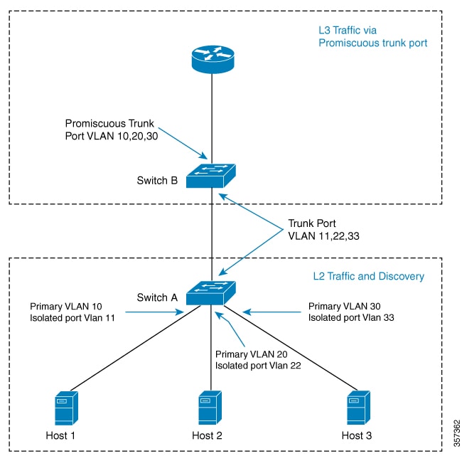
Hosts connected to Switch A can communicate only with the promiscuous trunk port on the switch. The PVLAN can be extended to span across multiple switches by adding intermediate switches. If there is a switch (Switch C) between Switch A and Switch B, layer 2 trunk ports need to be configured on the intermediate links. In the case of a community VLAN, packets can be seen on other hosts within the same community VLAN.

When a host is connected to a switch port with a cable, it is placed into an isolated PVLAN where it cannot discover any other hosts. The host is then authenticated by the RADIUS server. If the port is placed in closed mode and is not authenticated, only Extensible Authentication Protocol over LAN (EAPoL) packets are allowed. Once the port is authenticated, it is placed into an isolated VLAN dynamically.

When the host first authenticates with the RADIUS server, it sends the name of a dynamic interface template to be applied to the host's port. This interface template contains the configurations to enable the PVLAN primary and secondary VLANs on the port. With the template applied to the host, the switchport mode changes, causing the port to flap from access mode to PVLAN mode.


Note


Traffic from multiple clients on the same interface will not be blocked.


Note


The interface template with the same name as referred by AAA Authorization needs to be configured on the switch.


When the interface template is applied, the port will physically go down for a time period set by the sticky timer and come up again. When the RADIUS server sends the interface template a second time, it is ignored as the conversion has been completed. The port is then assigned to a PVLAN which keeps it isolated. The host completes authorization and comes up to ready state.

Figure 1. PVLAN topology diagram

Configuring sticky timer for interface template

Configure the keep time for which the interface template information is retained before it is removed from the port using the access-session interface-template sticky timertime command.

PVLAN isolation compared to private rooms

PVLAN isolation is similar to placing each client in a private room, where they cannot see or communicate with other clients except through a central access point.

Restrictions for wired dynamic PVLAN

  • High availability is not supported with wired dynamic PVLAN.

  • Voice VLAN configuration cannot co-exist with this feature.

  • Local Web Authentication (LWA) and Central Web Authentication (CWA) cannot be used with this feature.

  • All wired clients using the dynamic PVLAN interface template will be programmed as data clients.

  • Only interfaces with existing Access or PVLAN Host switchport mode support PVLAN template.

  • Identity Based Networking Services 2.0 (IBNS 2.0) must be used for dynamic template support.

Configure wired dynamic PVLAN

Configure wired dynamic PVLAN to segment network traffic and enhance security by isolating ports and associating VLANs. This task enables the creation and association of primary and secondary VLANs, and applies interface templates for authenticated clients.

  • Establish isolated and primary VLANs for port isolation.

  • Associate secondary VLANs with the primary VLAN.

  • Apply interface templates for authenticated clients using RADIUS or ISE.

Use this task to configure wired dynamic PVLAN on a user switch, such as switch A in the topology. This configuration is relevant when you need to segment ports for security and apply dynamic templates based on client authentication.

Before you begin

Ensure that dot1x AAA is configured on the user switch.

Verify that the user switch supports PVLAN and interface templates

Procedure


Step 1

Configure private VLAN

  1. Use the enable command to enter privileged EXEC mode.

    Example:

    Switch> enable

    Enter your password if prompted.

  2. Use the configure terminal command to enter global configuration mode.

    Example:

    Switch# configure terminal
  3. (Optional) Use the VLAN vlan-id command to create or select the isolated VLAN.

    Example:

    Switch(config)# vlan 200

    The VLAN ID range is 2 to 1001 and 1006 to 4094.

  4. Use the private-VLAN isolated command to designate the VLAN as an isolated VLAN.

    Example:

    Switch(config-vlan)# private-vlan isolated
  5. Use the exit command to return to global configuration mode.

    Example:

    Switch(config-vlan)# exit
  6. Use the VLAN vlan-id command to create or select the primary VLAN.

    Example:

    Switch(config)# vlan 100
  7. Use the private-VLAN primary command to designate the VLAN as a primary VLAN.

    Example:

    Switch(config-vlan)# private-vlan primary
  8. Use the private-VLAN association [add | remove] secondary_vlan_list command to associate secondary VLANs with the primary VLAN.

    Example:

    Switch(config-vlan)# private-vlan association 200
    • The secondary_vlan_list parameter cannot contain spaces. It can contain multiple comma-separated items. Each item can be a single private-VLAN ID or a hyphenated range of private-VLAN IDs.

    • The secondary_vlan_list parameter can contain multiple community VLAN IDs but only one isolated VLAN ID.

    • Enter a secondary_vlan_list , or use the add keyword with a secondary_vlan_list to associate secondary VLANs with a primary VLAN.

    • Use the remove keyword with a secondary_vlan_list to clear the association between secondary VLANs and a primary VLAN.

    • The command does not take effect until you exit VLAN configuration mode.

  9. Use the exit command to return to global configuration mode.

    Example:

    Switch(config-vlan)# exit

Step 2

Configure interface

  1. Use the template template-name command to create a user template and enter template configuration mode.

    Example:

    Switch(config)# template PVLAN100_200_CFG
  2. Use the switchport mode private-VLAN host command to configure a layer 2 port as a PVLAN host port on the template.

    Example:

    Switch(config-template)# switchport mode private-vlan host
  3. Use the switchport private-VLAN host-association primary_vlan_id secondary_vlan_id command to configure the association of a layer 2 port with a PVLAN on the template.

    Example:

    Switch(config-template)# switchport private-vlan host-association 100 200
  4. Use the exit command to return to global configuration mode.

    Example:

    Switch(config-template)# exit
  5. Use the access-session interface-template sticky timer time command to configure the global sticky timer for the template.

    Example:

    Switch(config)# access-session interface-template sticky timer 60

    Configures the keep time of the template globally. Once the last client leaves, the template will be removed from the port after the configured keep time.

    Note


    It is recommended that you set the sticky timer to 60 seconds.

  6. Use the interface interface-ID command to enter interface configuration mode for the specified interface.

    Example:

    Switch(config)# interface GigabitEthernet1/0/1
  7. Use the access-session interface-template sticky timer time command to configure the sticky timer on the specific interface.

    Example:

    Switch(config-if)# access-session interface-template sticky timer 60

    Configures the keep time of the template on the interface. Once the last client leaves, the template will be removed from the port after the configured keep time.

    Note


    It is recommended that you set the sticky timer to 60 seconds.

  8. Use the end command to return to privileged EXEC mode.

    Example:

    Switch(config-if)# end

What to do next

Once you comple the wired dynamic PVLAN configuration, configure the Identity Services Engine (ISE) or any other RADIUS server to assign the template to the client’s port interface after the client has been authenticated successfully.

If you are using the ISE, go to the Policy > Policy Elements > Authorization > Authorization Profile page. Check the Interface Template check box and enter the name of the template to be assigned to the client interface.

If you are using a different RADIUS server, the attribute Cisco-AVpair="interface:template=name" must be pushed to the switch after the initial client authentication has been completed.