High-availability Seamless Redundancy

Feature History

This topic provides the release and feature information for High-Availability Seamless Redundancy (HSR)—HSR-SAN (Single RedBox mode).

Table 1. Feature History Table

Feature Name

Release

Feature Information

High-Availability Seamless Redundancy (HSR)—HSR-SAN (Single RedBox mode)

Cisco IOS XE 17.13.1

Initial support for Cisco Catalyst IE9300 Rugged Series Switches

High-availability Seamless Redundancy

High-availability Seamless Redundancy (HSR) is a network protocol defined in IEC 62439-3-2016 that provides seamless redundancy in ring topologies by sending traffic in both directions and using protocol-specific information to eliminate duplicate packets.

  • HSR operates in a ring topology, with Port-A sending traffic counterclockwise and Port-B sending traffic clockwise.

  • The HSR packet format includes a header (HSR header) containing a sequence number to identify duplicate frames.

  • HSR is similar to Parallel Redundancy Protocol (PRP), but differs in topology and packet format; PRP uses a redundancy control trailer (RCT) instead of a header.

HSR protocol operation and device support


Note


HSR is supported on specific Cisco Catalyst IE9300 Rugged Series Switches SKUs. For information about supported SKUs, refer to the Guidelines and Limitations section in this guide. The term switch in this document refers to a Cisco Catalyst IE9300 Rugged Series Switch unless otherwise noted.


  1. In this release, the switch supports only an HSR Singly Attached Node (SAN) and only one HSR instance.

  2. You can create only one HSR instance or one PRP instance. If you have created a PRP instance, no HSR instance can be created.

  3. Non-switching nodes with two interfaces attached to the HSR ring are referred to as Doubly Attached Nodes implementing HSR (DANHs).

  4. Singly Attached Nodes (SANs) connect to the HSR ring through a device called a RedBox (Redundancy Box).

  5. The RedBox acts as a DANH for any traffic when it is the source or the destination. The switch implements RedBox functionality using Gigabit Ethernet port connections to the HSR ring.

  6. The following figure shows an example of an HSR ring as described in IEC 62439-3. In this example, the RedBox is an Cisco Catalyst IE9300 Rugged Series Switch.

    Figure 1. Example of HSR ring carrying unicast traffic


  7. Devices that do not support HSR must not connect directly to the HSR ring. Examples include laptops and printers. All HSR-capable devices must process the HSR header on received ring packets. They must also add the HSR header to packets sent into the ring.

  8. Non-HSR devices connect to the HSR ring through a RedBox. As shown in the figure, the RedBox has two ports on the DANH side. Non-HSR SAN devices connect to the upstream switch ports.

  9. The RedBox generates supervision frames for these devices. This makes them appear as DANH devices on the ring. Because the RedBox emulates these as DANH, they are called Virtual Doubly Attached Nodes (VDAN).

Loop avoidance mechanisms

Loop avoidance is a mechanism in HSR rings that prevents data frames from circulating endlessly, ensuring efficient use of network bandwidth and avoiding network loops.

  • Each node forwards frames from one HSR port to the other, but the RedBox does not retransmit frames already sent in the same direction.

  • Unicast packets destined for nodes inside the ring are consumed by the destination node and not forwarded further.

  • Packets that complete a loop are detected and dropped by the originating node to prevent looping.

Loop avoidance in HSR rings is achieved through specific forwarding and dropping behaviors for unicast and multicast packets.

  • Unicast packet with destination inside the ring: When the unicast packet reaches the destination node, the packet is consumed by the respective node and is not forwarded.

  • Unicast packet with destination not inside the ring: This packet does not have a destination node in the ring, so every node forwards it until it returns to the originating node. Each node tracks the packets it sends and their direction. When the originating node recognizes that the packet has completed a loop, it drops the packet.

  • Multicast packet: Each node forwards a multicast packet, as there can be more than one recipient. As a result, the multicast packet always returns to the originating node. Every node checks whether it has already forwarded the packet through its outgoing interface. When the packet returns to the originating node, the node identifies it as already forwarded and drops it instead of forwarding it again.

HSR RedBox operation modes

The HSR RedBox enables connectivity between SAN devices and HSR rings. It can also bridge HSR and PRP networks or connect two HSR rings, depending on its mode of operation.

  • HSR-SAN mode connects SAN devices to an HSR ring and represents SAN devices as VDANs on the ring.

  • HSR-PRP mode bridges HSR and PRP networks by converting frames between the two protocols.

  • HSR-HSR mode connects two HSR rings using a QuadBox device, associating switch ports with each ring.

Supported HSR RedBox modes

The HSR RedBox can operate in several modes. Each mode defines how packets are handled in different network scenarios.

  • HSR-SAN : The most basic mode, where the RedBox connects SAN devices to an HSR ring. No other PRP or HSR network is involved. Traffic on the upstream switch port does not have HSR/PRP tags, and the RedBox represents the SAN device as a VDAN in the ring.

  • HSR-PRP : Used to bridge HSR and PRP networks. The RedBox extracts data from the PRP frame and generates the HSR frame, and performs the reverse operation for packets in the opposite direction. More than one PRP network can be bridged to one HSR ring and vice versa.

  • HSR-HSR : Connects two HSR rings through a QuadBox device. Two ports on the switch are associated with one HSR ring, and the other two ports are associated with the second HSR ring. The remaining ports on the switch are shut down.


Note


In this release, the switch supports HSR-SAN mode only.


HSR RedBox in HSR-SAN mode

In HSR-SAN mode, the RedBox connects SAN devices to an HSR ring, and the RedBox represents each SAN device as a VDAN on the ring. No HSR or PRP tags are present on the upstream switch port traffic.

HSR SAN mode in RedBox ring topology

HSR SAN mode is a configuration in which the RedBox inserts the HSR tag for the host within a ring topology. The RedBox also manages forwarding of ring traffic, applying specific rules for handling frames, duplicates, and unique destinations.

In HSR SAN mode, packets are handled in these ways:

  • A source DANH sends a frame passed from its upper layers (C frame). It prefixes the frame with an HSR tag to identify frame duplicates and sends the frame over each port (A frame and B frame).

  • A destination DANH receives two identical frames from each port within a certain interval. The destination DANH removes the HSR tag of the first frame before passing it to its upper layers and discards any duplicate.

  • Each node in the HSR ring forwards frames received from one port to the other port of the HSR pair. However, specific exceptions apply:

    • The received frame returns to the originating node in the ring.

    • The frame is a unicast frame with a destination MAC address of a node upstream of the receiving node.

    • The node had already sent the same frame in the same direction. This rule prevents a frame from spinning in the ring in an infinite loop.

CDP and LLDP for HSR

HSR supports the Cisco Discovery Protocol (CDP) and Link Layer Discovery Protocol (LLDP). CDP and LLDP are Layer 2 neighbor discovery protocols. Both CDP and LLDP can provide information about nodes directly connected to the device. They also provide additional information, including the local and remote interface names and device names.

When CDP or LLDP is enabled, you can use the CDP or LLDP information to find the adjacent nodes on an HSR ring and their status. You can use the neighbor information from each node to determine the complete HSR network topology. Additionally, you can debug and locate ring faults.

CDP and LLDP are configured on physical interfaces only.

For more information, see Configuring an HSR Ring and Verifying Configuration.

HSR alarms

  • HSR alarms are generated by an HSR RedBox when one or both physical ring ports/links are down.

  • Partial Ring Fault occurs when one ring port or link is down. Packets can still be sent using the redundant path, but user intervention is required.

  • Full Ring Fault occurs when both ring ports or links are down. This major fault requires immediate attention and can trigger an external hardware alarm relay.

HSR alarm types, notifications, and event representation

HSR rings can generate partial and full ring fault alarms, each with specific notification mechanisms and system representations.

  • Syslog: Generated when the alarm is raised or cleared.

  • SNMP Notification: Sent when the alarm is raised or cleared.

  • Relay output: External relay contacts are asserted or de-asserted in response to the alarm. Relays are activated by major faults only.

This table lists the HSR events and their representations.

Table 2. HSR Events and Representations

Event Number

Event Description

System Log (Level)

Alert/Alarm Log

Alarm LED and Output relay

1

Ring goes from UP to DOWN state.

2

2

Major Alarm/Assert

2

Ring goes from DOWN to UP state.

6

6

De-assert

3

One ring port goes DOWN. The other ring port and the ring itself are UP.

3

3

4

Both ring ports are UP again.

6

6


Note


See Enable HSR alarms for steps to configure HSR alarms.


You can view currently active alarms using the show facility alarm status command. The following example shows alarm status for minor and major HSR alarms:

Switch# show facility-alarm status
Source          Severity    Description                      Relay   Time
Switch            MINOR    34 HSR ring is partially down        MAJ    Oct 24 2017 10:16:10 
-------
Switch# show facility-alarm status
Source          Severity    Description                   Relay     Time
Switch            MAJOR    33 HSR ring is down               MAJ      Oct 24 2017 10:17:07
                    

HSR alarm syslog examples

The following examples show the syslog entries that are generated for each HSR alarm event assertion and clear event (if configured):

  • Syslog generated on occurrence of Partial fault:

    Oct 24 11:07:13.952 IST: %HSR_ALARM-3-HSR_PARTIALFAULT: The HSR ring in now in PARTIAL FAULT state
                            
  • Syslog generated when the Partial fault is cleared:

    Oct 24 11:07:38.032 IST: %HSR_ALARM-3-HSR_PARTIALFAULT: The HSR ring in now in PARTIAL FAULT state - event cleared
                            
  • Syslog generated on occurrence of Full fault:

    Oct 24 11:07:38.036 IST: %HSR_ALARM-2-HSR_RINGFAULT: The HSR ring in now in FAULT state
  • Syslog generated when the Full fault is cleared:

    Oct 24 11:08:19.082 IST: %HSR_ALARM-2-HSR_RINGFAULT: The HSR ring in now in FAULT state - event cleared
                            

Guidelines for configuring HSR on IE9300 Series switches

When configuring HSR and related modes on IE9300 Series switches, follow these guidelines and limitations:

HSR-SAN is supported on the following Cisco Catalyst IE9300 Rugged Series Switches:

  • IE-9310-16P8S4X-E and IE-9310-16P8S4X-A

  • IE-9320-26S2C-E and IE-9320-26S2C-A

  • IE-9320-22S2C4X-E and IE-9320-22S2C4X-A

The interfaces supported for the HSR ring on IE-9310-16P8S4X-E and IE-9310-16P8S4X-A are listed in the table.

Table 3. Channel and interface details

Channel

Interface

HSR-Ring 1

Gi1/0/1-2 or Gi1/0/9-10

The interfaces supported for HSR ring on IE-9320-26S2C-E , IE-9320-26S2C-A , IE-9320-22S2C4X-E , and IE-9320-22S2C4X-A are:

Table 4. Channel and interface details

Channel

Interface

HSR-Ring 1

Gi1/0/21-22 or Gi1/0/23-24

  1. Deployment, instance, and licensing restrictions

    HSR is supported only in a standalone deployment; there is no support for HSR for stacked switches. Only one HSR instance is supported. The switch supports only one HSR or one PRP instance. If a PRP instance has been created, you cannot create an HSR instance. The HSR feature requires the Network Essentials license. The HSR feature is not enabled by default. You must configure the HSR rings explicitly. HSR is disabled automatically if the required firmware image is not available on the system.

  2. Interface assignment and ring mode restrictions

    Physical interfaces are predefined for the rings and ports in HSR-SAN, HSR-PRP, and HSR-HSR modes and cannot be changed. The table lists port assignments for each HSR mode. Ring 1 and Ring 2 support configuration in HSR-SAN mode. On the IE 4000 in HSR-PRP Dual RedBox mode, three ports participate in the HSR-PRP network. Only Ring 2 can be configured in this mode.

  3. Port settings and compatibility requirements

    After including a port in a ring, you cannot change its media-type, speed, or duplex settings. Set these options before assigning ring membership. It is important for all interfaces in an HSR ring to have the same speed and duplex settings. Apply those settings before configuring ring membership. Both ports of one ring must be of same speed and type (that is, both can be SFPs or both can be copper). VLAN configuration such as trunk and access mode must be the same on both the ports participating in the ring. If you change the mode of HSR interfaces from access to trunk or trunk to access after configuring the ring, flap the HSR ring.

  4. Node scale, ring limits, and port support

    The recommended maximum number of nodes in the node table is 512. Nodes include all DANH and VDAN devices connected to the ring. This number is not a strict limit. Adding more entries may increase duplicate packets for end devices. The maximum number of nodes in the HSR ring is 50. HSR ring ports can only be configured in L2 mode. HSR is supported on following port types:

    • 100 mbps, Full Duplex. Half duplex is not supported

    • 1000 mbps, Full Duplex. Half duplex is not supported

    • HSR is not supported on the uplink ports

  5. Mutually exclusive protocols and unsupported features

    The following protocols and features are mutually exclusive with HSR on the same port: PRP, EtherChannels, Link Aggregation Control Protocol (LACP), Port Aggregation Protocol (PAgP), and REP. MACsec, HSR, and PRP are not allowed together. PTP over HSR is not supported. STP is not supported on the HSR ring. By default, all modes of Spanning Tree Protocol (STP) will be disabled on the ring ports. Switched Port Analyzer (SPAN) and Remote SPAN (RSPAN) are not supported on HSR. SPAN and RSPAN should not be used to monitor the traffic on an HSR ring. In addition, traffic that has been monitored using RSPAN should not be transferred over an HSR ring.

  6. MTU and operational behavior

    HSR supports an MTU size of up to 1998 bytes of Ethernet payload. After an interface is added in the HSR ring, only the primary interface counters are updated. You should not need to configure and check the status of individual physical interfaces after they are added to the HSR ring.

  7. Port shutdown restriction

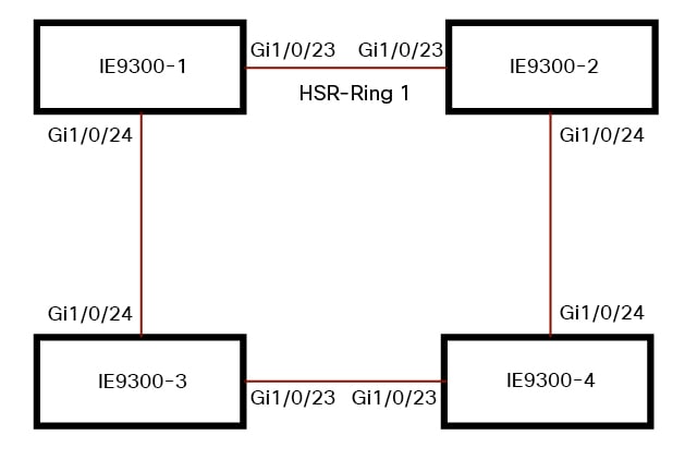
    Once a port is part of ring, the port cannot be shut down. For example, if Gi1/0/23 and Gi1/0/24 are part of an HSR ring and you try to shut down Gi1/0/23 or Gi1/0/24, the operation will not be permitted:
    Switch(config)# <userinput>interface range gi1/0/23-24</userinput>
    Switch(config-if-range)#<userinput>shutdown</userinput>
     %Interface GigabitEthernet1/0/23 is configured in a HSR ring shutdown not permitted!
    Switch(config-if-range)# 

    You can perform a shutdown of the HSR ring. For example:

    <userinput>Switch# conf t</userinput>
    Switch(config)#<userinput>int hs1</userinput>
    Switch(config-if-range)#<userinput>shut</userinput>
  8. VLAN mismatch behavior

    VLAN configuration such as trunk and access mode must be the same on both the ports participating in the ring. For example, if Gi1/0/24 and Gi1/0/23 in an HSR ring are in trunk mode and you attempt to change the mode of one port to access, the ports in the ring will not be bundled:

    Switch(config)# <userinput>interface range gi1/0/23-24</userinput>
    Switch(config-if-range)# <userinput>switchport mode  access</userinput>
    Jul 27 22:00:27.809 IST: %EC-5-CANNOT_BUNDLE2: Gi1/0/23 is not compatible with Gi1/0/24 and will be suspended (trunk mode of Gi1/0/23 is access, Gi1/0/24 is dynamic)
    
  9. MAC flap prevention during HSR ring configuration

    Configuring an HSR ring on two ports of a switch causes MAC flaps on other switches without the HSR configuration. Shut down the newly created HSR ring on the switch, configure the ring on all switches, and then re-enable the rings one at a time. For example, if there are four switches in the ring, disable the HSR ring interfaces on each switch:

    Switch1(config)# <userinput>interface range gi1/0/21-22</userinput>
    Switch1(config-if-range)# <userinput>shutdown</userinput>
    Switch1(config-if-range)# <userinput>hsr-ring 1</userinput>
    Creating a HSR-ring interface hs1
    Switch1(config-if-range)# <userinput>int hs1</userinput>
    Switch1(config-if-range)# <userinput>shutdown</userinput>
    Switch1(config-if-range)# <userinput>end</userinput>

    After all four switches are configured with the ring, re-enable the HSR ports on each switch:

    Switch1# <userinput>conf t</userinput>
    Enter configuration commands, one per line. End with CNTL/Z.
    Switch1(config)# <userinput>interface range gi1/0/21-22</userinput>
    Switch1(config-if-range)# <userinput>int hs1</userinput>
    Switch1(config-if-range)# <userinput>no shutdown</userinput>
    Switch1(config-if-range)# <userinput>end</userinput>
    Switch1#
    

    This process prevents temporary MAC flapping during HSR ring configuration in member switches.

HSR-PRP dual RedBox mode

  1. Adhere to these restrictions when configuring HSR-PRP Dual RedBox mode to ensure correct operation and avoid loss of connectivity or configuration.

  2. Because three ports participate in the HSR-PRP network, only HSR ring 2 can be configured in HSR-PRP mode.

  3. Interface assignment is fixed and cannot be changed. Refer to the table above for the assigned interfaces in HSR-PRP mode.

  4. When HSR-PRP Dual RedBox mode is configured and enabled, all other ports apart from the 3 HSR-PRP ports are shut down and any feature running on any of these ports will not be functional. You will be warned about this mode change.

  5. When HSR-PRP RedBox is active, all other interfaces that are not part of the RedBox remain in the shutdown state and are unusable as long as the RedBox mode is active.

  6. Management of the switch through Device Manager is still possible with an in-band SVI interface reachable over the HSR Ring or PRP network. However, there will be loss of connection for a period of time when RedBox mode is enabled or disabled and the device reconfigures itself. Therefore, we highly recommend that you use a console connection when switching into or out of HSR-PRP mode.

  7. When HSR-PRP mode is disabled, all physical interfaces will return to their default configuration (that is, configuration on non-RedBox physical ports will be lost).

  8. In HSR-PRP mode, by design PRP/HSR channel 1 (gi1/0/21-22) operates in "PRP/HSR disabled" mode. Frames coming into these two ports are passed through to the hardware for switching to the HSR-PRP enabled channel 2. Because channel 1 is not used for PRP or HSR in HSR-PRP mode, the show prp channel 1 detail command displays "Protocol = Disabled" even though the Port state displays "Inuse".

  9. In HSR-PRP Dual RedBox mode, during reload of the HSR-PRP switch when the traffic is in progress, MAC flaps occur once per source MAC address in the switch that is reloaded and also on the PRP device that is transmitting the traffic. Therefore, if there are 512 different source MAC addresses, then MAC flaps are observed 512 times (once per source MAC address). Also some duplicate packets are seen after this event.

HSR-HSR QuadBox mode

To ensure correct operation and avoid loss of connectivity or configuration when configuring HSR-HSR QuadBox mode, please adhere to the following restrictions:

  1. Interface and Port Assignment: Interface assignment is fixed and cannot be changed. When HSR-HSR QuadBox mode is enabled, all ports other than the four designated HSR-HSR ports are shut down; any features running on those ports will not be functional, and all interfaces not part of the RedBox remain unusable.

  2. Management Recommendations: While management via Device Manager is possible using an in-band SVI interface, a connection loss will occur during mode transitions. It is highly recommended to use a console connection when enabling or disabling HSR-HSR mode.

  3. Configuration Reset: When HSR-HSR mode is disabled, all physical interfaces will return to their default configuration, meaning any previous configuration on non-QuadBox physical ports will be lost.

  4. MAC Address and Packet Handling: To prevent MAC address flapping caused by redundant packets arriving on different rings, MAC address learning is disabled. Because all other ports are shut down, unnecessary flooding of packets does not occur.

  5. Topology Consistency: When the topology includes more than one QuadBox, the VLAN and multicast filter configurations must match on all QuadBoxes.

  6. Access and MTU Restrictions: Switch port mode access is restricted, the MTU size is fixed at 2020 and cannot be altered, and MAC address table learning for VLANs 1-4094 is disabled.

  7. Feature and Command Limitations: PTP is disabled by default (due to no FPGA support). Additionally, show and clear commands for Node/VDAN tables, HSR ring proxyNodeTableForgetTime, HSR ring nodeforgetTime, and the creation of independent HSR ring interfaces are restricted in the HSR-HSR profile.

  8. Multicast Filter Behavior: Multicast filters are designed to drop only Multicast MACDA; filters set as Unicast MAC addresses will not result in any packet drops.

Default settings

This topic provides a reference for the default settings and parameters used in HSR ring configurations.

Table 5. HSR ring parameters

Parameter

Description

Range

Default Value

entryForgetTime

Time for clearing an inactive entry from duplicate discard table.

0-65535

400 ms

fpgamode-DualUplinkEnhancement

Sets the FPGA register to filter source MAC addresses.

enable or disable

enable

nodeForgetTime

Clears an inactive entry from the node table after a set time interval.

0-65535

60000 ms

nodeRebootInterval

Specifies when the RedBox starts sending supervision frames after bootup.

0-65535

500 ms

pauseFrameTime

Specifies the interval between HSR pause frames.

0-65535

25 ms

proxyNodeTableForgetTime

Clears an inactive entry from the proxy node table or vdan table after a set interval.

0-65535

60000 ms

supervisionFrameLifeCheckInterval

Specifies the life check interval for supervision frames.

0-65535

1600 ms

supervisionFrameOption

mac-da

Specifies the last bytes of the destination MAC address for supervision frames (01:15:4E:00:01:00). The final pair, '00,' is replaced by the value of this parameter.

1-255 MAC DA last eight bits option value

No default

vlan-cfi

Enables the Canonical Format Indicator (CFI) for the VLAN-tagged frame.

enable or disable

disable

vlan-cos

Sets the Class of Service (COS) value in the VLAN tag of the supervision frame.

0-7

0

vlan-id

Specifies the VLAN tag for the supervision frame.

0-4095

0

vlan-tagged

Specifies the VLAN tagging option.

enable or disable

disable

supervisionFrameRedboxMacaddress

Specifies the RedBox MAC address included in supervision frames.

48-bit RedBox MAC address

The interface HSR ring MAC address

supervisionFrameTime

Specifies the interval between supervision frames.

0-65535

3 ms

Configure an HSR ring

Follow these steps to configure an HSR ring:

Before you begin

Procedure


Step 1

(Optional) Use the cdp run command to globally enable CDP to provide information about HSR ring nodes.

Step 2

(Optional) Use the lldp run command to globally enable LLDP to provide information about HSR ring nodes.

Step 3

Use the interface range range command to enter interface configuration mode and disable PTP on the ports to be assigned to the HSR ring.

Example:

Switch(config)# interface range gi1/0/21-22
Switch(config-if-range)# no ptp enable

Step 4

(Optional) Use the cdp enable command to enable CDP on the ports to be assigned to the HSR ring.

Step 5

(Optional) Use the lldp transmit command to enable LLDP on the ports to be assigned to the HSR ring.

Example:

Switch(config-if-range)# lldp transmit
Switch(config-if-range)# lldp receive

Step 6

Use the shutdown command to shut down the ports before configuring the HSR ring.

Step 7

Use the interface range range command to create the HSR ring interface and assign the ports to the HSR ring.

Example:

Switch(config)# interface range gigabitEthernet 1/0/21-22
Switch(config-if-range)# hsr-ring 1

Step 8

(Optional) If required, use the hsr hsr-id supervisionFrameLifeCheckInterval interval range command configure HSR ring optional parameters. Refer to the Default Settings section for descriptions of parameters, ranges, and default values.

Example:

Switch(config-range)# hsr 1 supervisionFrameLifeCheckInterval 10000

Step 9

use the no shutdown command to turn on the HSR interface.

Example:

Switch(config-if-range)# no shutdown
Switch(config-if-range)# end

Switch# conf t
Enter configuration commands, one per line.  End with CNTL/Z.
Switch(config)# interface range gigabitEthernet 1/0/21-22
Switch(config-if-range)# no ptp enable
Switch(config-if-range)# shutdown
Switch(config-if-range)# hsr-ring 1
Switch(config-if-range)# hsr-ring 1 supervisionFrameLifeCheckInterval 10000
Switch(config-if-range)# no shutdown
Switch(config-if-range)# end

Enable HSR alarms

Enable or disable alarms and actions for HSR at the facility level. You cannot selectively enable partial or full faults. All alarms for a given facility are either enabled or disabled.

See HSR alarms for details about HSR alarms.

Use this procedure to enable alarms for HSR and configure related notification and logging options.

Before you begin

Ensure you have access to the device and the appropriate privileges to configure alarm facilities.

Procedure


Step 1

Use the configure terminal command to enter the global configuration mode.

Step 2

Use the alarm facility hsr enable command to enable the HSR alarm facility.

Note


Use the no alarm facility hsr enable command to disable HSR alarms.

Step 3

(Optional) Use the alarm facility hsr notifies command to enable SNMP notification for HSR alarms.

Step 4

(Optional) Use the alarm facility hsr relay major command to associate HSR alarms with the Major Relay.

Step 5

(Optional) Use the alarm facility hsr syslog command to send HSR alarms to a syslog server.

Step 6

(Optional) Use the logging alarm informational command to enable logging of informational HSR alarm messages.

Step 7

Use the logging alarm informational command to exit global configuration mode.


HSR alarms are enabled and configured as required. You can verify the status using the show facility-alarm status command.

Clear all node table and VDAN table dynamic entries

Procedure


Step 1

Use the clear hsr node-table command to clear all dynamic entries in the node table.

Step 2

Use the clear hsr vdan-table command to clear all dynamic entries in the VDAN table.


HSR verification commands

A HSR verification feature is a diagnostic capability on Cisco switches that

  • enables users to confirm the correct configuration and operation of HSR rings,

  • provides access to relevant commands and their output for troubleshooting, and

  • supports interpretation of filtering, statistics, and neighbor discovery information.

Command reference for verifying HSR configuration

This table lists the primary commands used to verify HSR ring configuration and their purposes.

Table 6. HSR verification commands

Command

Purpose

show hsr ring 1 [ detail ]

Shows configuration details for the specified HSR ring.

show hsr statistics { egressPacketStatistics | ingressPacketStatistics | nodeTableStatistics | pauseFrameStatistics}

Shows statistics for HSR components.

Note


To clear HSR statistics information, use the command clear hsr statistics .

show hsr node-table

Shows HSR node table.

show hsr vdan-table

Shows HSR Virtual Doubly Attached Node (VDAN) table.

Note


The VDAN table and Proxy node table are the same.

show cdp neighbors

Shows CDP neighbor information for an HSR ring.

show lldp neighbors

Shows LLDP neighbor information for an HSR ring.

Verifying HSR ocnfiguration and neighbor information

These examples show how to use verification commands and interpret their output for HSR rings, multicast/VLAN filtering, and neighbor discovery.

 Switch# show hsr ring detail
HSR-ring listing:
--------------------
HSR-ring: HS1
------------
 Layer type = L2
 Operation Mode = mode-H
 Ports: 2       Maxports = 2
 Port state = hsr-ring is Inuse
 Protocol = Enabled  Redbox Mode = hsr-hsr
Ports in the ring:
1) Port: Gi1/1
Logical slot/port = 1/1      Port state = Inuse
Protocol = Enabled
2) Port: Gi1/2
Logical slot/port = 1/2      Port state = Inuse
Protocol = Enabled
Ring Parameters:
 Redbox MacAddr: 70db.984a.5040
 Node Forget Time: 60000 ms
 Node Reboot Interval: 500 ms
 Entry Forget Time: 400 ms
 Proxy Node Forget Time: 60000 ms
 Supervision Frame COS option: 0
 Supervision Frame CFI option: 0
 Supervision Frame VLAN Tag option: Disabled
 Supervision Frame MacDa: 0x00
 Supervision Frame VLAN id: 0
 Supervision Frame Time: 3 ms
 Life Check Interval: 1600 ms
 Pause Time: 25 ms
 fpgamode-DualUplinkEnhancement: Enabled
HSR-ring: HS2
------------
 Layer type = L2
 Operation Mode = mode-H
 Ports: 2       Maxports = 2
 Port state = hsr-ring is Inuse
 Protocol = Enabled  Redbox Mode = hsr-hsr
Ports in the ring:
1) Port: Gi1/3
Logical slot/port = 1/3      Port state = Inuse
Protocol = Enabled
2) Port: Gi1/4
Logical slot/port = 1/4      Port state = Inuse
Protocol = Enabled
Ring Parameters:
 Redbox MacAddr: 70db.984a.5040
 Node Forget Time: 60000 ms
 Node Reboot Interval: 500 ms
 Entry Forget Time: 400 ms
 Proxy Node Forget Time: 60000 ms
 Supervision Frame COS option: 0
 Supervision Frame CFI option: 0
 Supervision Frame VLAN Tag option: Disabled
 Supervision Frame MacDa: 0x00
 Supervision Frame VLAN id: 0
 Supervision Frame Time: 3 ms
 Life Check Interval: 1600 ms
 Pause Time: 25 ms
 fpgamode-DualUplinkEnhancement: Enabled
Switch#
Switch# show hsr ring multicast-filter
HSR-ring listing:
--------------------
HSR-ring: HS1
---------------
Filter No.  Address         Mask
=============================================
2           0000.0100.0a00 ffff.ffff.ffff
HSR-ring: HS2
---------------
Filter No.  Address         Mask
=============================================
5           0000.0100.0b00 0000.0000.0000
                                         
Switch# show hsr ring allowed-vlan
HSR-ring listing:
--------------------
HSR-ring: HS1
---------------
Vlan allowed list
----------------------
0-4094
HSR-ring: HS2
---------------
Vlan allowed list
----------------------
0-4094
Switch# show hsr ring multicast-filter-drop
HSR-ring listing:
--------------------
HSR-ring: HS1
---------------
Multicast filter drop count: 0
HSR-ring: HS2
---------------
Multicast filter drop count: 0
Switch# show hsr ring allowed-vlan
HSR-ring listing:
--------------------
HSR-ring: HS1
---------------
Vlan allowed list
----------------------
0-4094
HSR-ring: HS2
---------------
Vlan allowed list
----------------------
0-4094
Switch#
                

This example shows how to check CDP neighbor information for an HSR ring. In this example, there are three switches, and CDP is enabled on all three.

DUT 2# sh cdp neighbors
Capability Codes: R - Router, T - Trans Bridge, B - Source Route Bridge
                  S - Switch, H - Host, I - IGMP, r - Repeater, P - Phone, 
                  D - Remote, C - CVTA, M - Two-port Mac Relay 
Device ID        Local Intrfce     Holdtme    Capability  Platform  Port ID
DUT 1            Gig 1/3           160              S I   IE-4000-8 Gig 1/2
DUT 3            Fas 1/4           163              S I   IE-4000-8 Gig 1/1
Total cdp entries displayed : 2

This example shows how to check LLDP neighbor information for an HSR ring. This example uses the same topology as the previous figure. LLDP is enabled on all three switches.

DUT 2# sh lldp neighbors
Capability codes:
    (R) Router, (B) Bridge, (T) Telephone, (C) DOCSIS Cable Device
    (W) WLAN Access Point, (P) Repeater, (S) Station, (O) Other
Device ID           Local Intf     Hold-time  Capability      Port ID
DUT 1               Gi1/3          120        B               port-002
DUT 3               Gi1/4          120        B               port-001
Total entries displayed: 2

Configuration examples

A configuration example is a documentation asset that

  • illustrates recommended command-line sequences for configuring features on Cisco IE9300 and S5400 switches,

  • includes sample outputs to verify successful configuration for both HSR-SAN and HSR-PRP scenarios, and

  • supports users by providing step-by-step command demonstrations for practical reference.

HSR-SAN

This example shows the configuration of an HSR ring (Ring 1) using Gi1/0/23 and Gi1/0/24 ports between four devices.

Figure 3. HSR ring configuration with four devices


IE9300-1# conf t
Enter configuration commands, one per line.  End with CNTL/Z.
IE9300-1(config)# interface range gi1/0/23-24
IE9300-1(config-if-range)# shutdown
IE9300-1(config-if-range)# hsr-ring 1
IE9300-1(config-if-range)# no shutdown
IE9300-1(config-if-range)# end
IE9300-1#          
IE9300-2# conf t
Enter configuration commands, one per line.  End with CNTL/Z.
IE9300-2(config)# interface range gi1/0/23-24
IE9300-2(config-if-range)# shutdown
IE9300-2(config-if-range)# hsr-ring 1
IE9300-2(config-if-range)# no shutdown
IE9300-2(config-if-range)# end
IE9300-2#          
IE9300-3# conf t
Enter configuration commands, one per line.  End with CNTL/Z.
IE9300-3(config)# interface range gi1/0/23-24
IE9300-3(config-if-range)# shutdown
IE9300-3(config-if-range)# hsr-ring 1
IE9300-3(config-if-range)# no shutdown
IE9300-3(config-if-range)# end
IE9300-3#          
IE9300-4# conf t
Enter configuration commands, one per line.  End with CNTL/Z.
IE9300-4(config)# interface range gi1/0/23-24
IE9300-4(config-if-range)# shutdown
IE9300-4(config-if-range)# hsr-ring 1
IE9300-4(config-if-range)# no shutdown
IE9300-4(config-if-range)# end
IE9300-4#          
IE9300-1# sh hsr ring 1 detail
HSR-ring: HS1
------------
 Layer type = L2
 Operation Mode = mode-H
 Ports: 2       Maxports = 2
 Port state = hsr-ring is Inuse
 Protocol = Enabled  Redbox Mode = hsr-san
Ports in the ring:
  1) Port: Gi1/0/23
   Logical slot/port = 1/3      Port state = Inuse
        Protocol = Enabled
  2) Port: Gi1/0/24
   Logical slot/port = 1/4      Port state = Inuse
        Protocol = Enabled
Ring Parameters:
 Redbox MacAddr: f454.3365.8a84
 Node Forget Time: 60000 ms
 Node Reboot Interval: 500 ms
 Entry Forget Time: 400 ms
 Proxy Node Forget Time: 60000 ms
 Supervision Frame COS option: 0
 Supervision Frame CFI option: 0
 Supervision Frame VLAN Tag option: Disabled
 Supervision Frame MacDa: 0x00
 Supervision Frame VLAN id: 0
 Supervision Frame Time: 3 ms
 Life Check Interval: 2000 ms
 Pause Time: 25 ms
IE9300-2# show hsr ring 1 detail
HSR-ring: HS1
------------
 Layer type = L2
 Operation Mode = mode-H
 Ports: 2       Maxports = 2
 Port state = hsr-ring is Inuse
 Protocol = Enabled  Redbox Mode = hsr-san
Ports in the ring:
  1) Port: Gi1/0/23
   Logical slot/port = 1/3      Port state = Inuse
        Protocol = Enabled
  2) Port: Gi1/0/24
   Logical slot/port = 1/4      Port state = Inuse
        Protocol = Enabled
Ring Parameters:
 Redbox MacAddr: 34c0.f958.ee83
 Node Forget Time: 60000 ms
 Node Reboot Interval: 500 ms
 Entry Forget Time: 400 ms
 Proxy Node Forget Time: 60000 ms
 Supervision Frame COS option: 0
 Supervision Frame CFI option: 0
 Supervision Frame VLAN Tag option: Disabled
 Supervision Frame MacDa: 0x00
 Supervision Frame VLAN id: 0
 Supervision Frame Time: 3 ms
 Life Check Interval: 2000 ms
 Pause Time: 25 ms
IE9300-4# sh hsr ring 1 de
HSR-ring: HS1
------------
 Layer type = L2
 Operation Mode = mode-H
 Ports: 2       Maxports = 2
 Port state = hsr-ring is Inuse
 Protocol = Enabled  Redbox Mode = hsr-san
Ports in the ring:
  1) Port: Gi1/0/23
   Logical slot/port = 1/3      Port state = Inuse
        Protocol = Enabled
  2) Port: Gi1/0/24
   Logical slot/port = 1/4      Port state = Inuse
        Protocol = Enabled
Ring Parameters:
 Redbox MacAddr: f454.3312.5104
 Node Forget Time: 60000 ms
 Node Reboot Interval: 500 ms
 Entry Forget Time: 400 ms
 Proxy Node Forget Time: 60000 ms
 Supervision Frame COS option: 0
 Supervision Frame CFI option: 0
 Supervision Frame VLAN Tag option: Disabled
 Supervision Frame MacDa: 0x00
 Supervision Frame VLAN id: 0
 Supervision Frame Time: 3 ms
 Life Check Interval: 2000 ms
 Pause Time: 25 ms
IE9300-3# sh hsr ring 1 detail
HSR-ring: HS1
------------
 Layer type = L2
 Operation Mode = mode-H
 Ports: 2       Maxports = 2
 Port state = hsr-ring is Inuse
 Protocol = Enabled  Redbox Mode = hsr-san
Ports in the ring:
  1) Port: Gi1/0/23
   Logical slot/port = 1/3      Port state = Inuse
        Protocol = Enabled
  2) Port: Gi1/0/24
   Logical slot/port = 1/4      Port state = Inuse
        Protocol = Enabled
Ring Parameters:
 Redbox MacAddr: f454.335c.4684
 Node Forget Time: 60000 ms
 Node Reboot Interval: 500 ms
 Entry Forget Time: 400 ms
 Proxy Node Forget Time: 60000 ms
 Supervision Frame COS option: 0
 Supervision Frame CFI option: 0
 Supervision Frame VLAN Tag option: Disabled
 Supervision Frame MacDa: 0x00
 Supervision Frame VLAN id: 0
 Supervision Frame Time: 3 ms
 Life Check Interval: 2000 ms
 Pause Time: 25 ms