PTP over PRP

PTP over PRP

Precision Time Protocol (PTP) can operate over Parallel Redundancy Protocol (PRP) on Cisco Catalyst IE9300 Rugged Series Switches.

PRP provides high availability through redundancy for PTP. For more information about PTP, see Precision Time Protocol Configuration Guide, Cisco Catalyst IE9300 Rugged Series Switches on Cisco.com.

The PRP method achieves redundancy by transmitting in parallel over two independent paths; however, this approach does not work for PTP. The delay that a frame experiences is not the same in the two LANs. In addition, some frames are modified in the transparent clocks (TCs) while transiting through the LAN. A Dually Attached Node (DAN) does not receive the same PTP message from both ports even when the source is the same. Specifically:

  • Sync/Follow_Up messages are modified by TCs to adjust the correction field.

  • Boundary Clocks (BCs) present in the LAN are not PRP-aware and generate their own Announce and Sync frames with no Redundancy Control Trailer (RCT) appended.

  • Follow_Up frames are generated by every 2-step clock and carry no RCT.

  • TCs are not PRP-aware and are not obliged to forward the RCT, which is a message part that comes after the payload.

Before PTP was supported over both LAN-A and LAN-B, PTP traffic was permitted only on LAN-A to avoid issues with PTP and parallel transmission. However, when LAN-A went down, the system lost PTP synchronization. To enable PTP to leverage the benefit of redundancy offered by the underlying PRP infrastructure, PTP packets over PRP networks are handled differently than other types of traffic.

The implementation of the PTP over PRP feature is based on the PTP over PRP operation that is detailed in IEC 62439-3:2016, Industrial communication networks - High availability automation networks - Part 3: Parallel Redundancy Protocol (PRP) and High-availability Seamless Redundancy (HSR) . This approach overcomes the problems mentioned earlier by not appending an RCT to PTP packets and bypassing the PRP duplicate/discard logic for PTP packets.

This table summarizes the feature support for the specified switch models and their corresponding minimum supported Cisco IOS XE software versions.

Table 1. Switch models and supported Cisco IOS XE software versions
Switch Model Supported IOS XE Version

IE-9320-26S2C-A

Cisco IOS XE Cupertino 17.9.1

IE-9320-26S2C-E

IE-9320-22S2C4X-A

Cisco IOS XE Dublin 17.12.1

IE-9320-22S2C4X-E

PTP over PRP packet flow

This figure illustrates the operation of PTP over PRP.

Figure 1. PTP over PRP Packet Flow

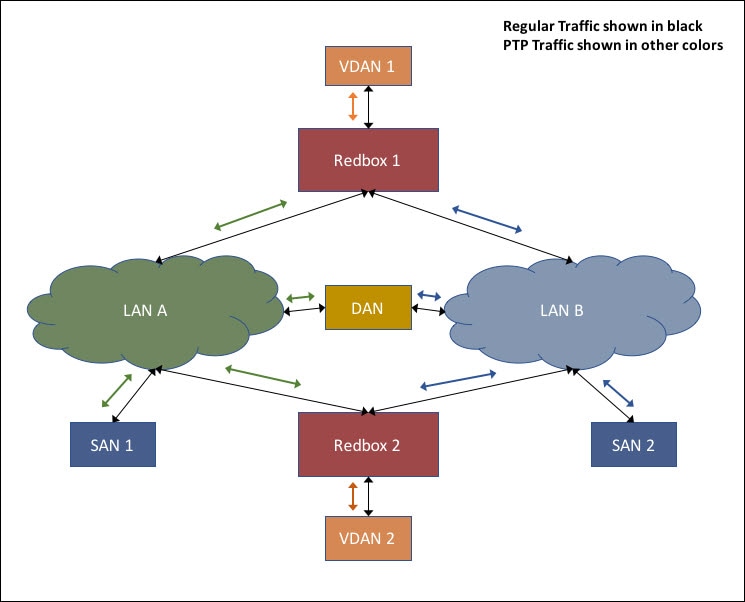
In the figure, VDAN 1 is the grandmaster clock (GMC). Dually attached devices receive PTP synchronization information over both their PRP ports. The LAN-A port and LAN-B port use a different virtual clock that is synchronized to the GMC. However, only one port known as time recipient, is used to synchronize the local clock (VDAN 2 in the figure). When the LAN-A port is serving as the time recipient, its virtual clock synchronizes VDAN 2. The other PRP port, LAN-B, is referred to as PASSIVE. The LAN-B port’s virtual clock stays synchronized to the GMC but does not synchronize VDAN 2.

If LAN-A goes down, the LAN-B port takes over as the time recipient and is used to continue synchronizing the local clock on RedBox 2. VDAN 2 attached to RedBox 2 continues to receive PTP synchronization from RedBox 2 as before. Similarly, all DANs, VDANs, and RedBoxes shown in the figure continue to remain synchronized. For SANs, redundancy is not available, and in this example, SAN 1 loses synchronization if LAN-A goes down.

When the time recipient port changes, VDAN 2 may experience an instantaneous shift in its clock because of the offset between the LAN-A and LAN-B virtual clocks. This shift should be only a few microseconds, since both clocks are synchronized to the same GMC. The shift also occurs when the LAN-A port resumes its role as time recipient and the LAN-B port becomes passive.


Note


Cisco is moving from the traditional Master/Slave nomenclature. In this document, the terms Grandmaster clock (GMC) or time source and time recipient are used instead, where possible. Exceptions may be present due to language that is hard-coded in the user interfaces of the product software, language used based on RFP documentation, or language that is used by a referenced third-party product.


Supported location of GMC

The GMC can be located in a PTP over PRP topology as one of these:

  • A RedBox that is connected to both LAN A and LAN B, for example, RedBox 1 in the figure.

  • A VDAN, for example, VDAN 1 in the figure.

  • A DAN, for example, the DAN in the figure.

The GMC cannot be a SAN attached to LAN-A or LAN-B, because only the devices in LAN-A or LAN-B will be synchronized to the GMC.

Configuration of PTP over PRP

PTP over PRP does not require configuration beyond how you would normally configure PTP and PRP separately. This feature does not include any new user interface. Previously, PTP operated only over LAN-A. With the PTP over PRP feature, it now operates over both LAN-A and LAN-B. Review the Guidelines and Limitations before implementing PTP over PRP.

Use this high-level workflow to implement PTP over PRP in your network.

  1. Refer to the section RedBox Types in this guide to determine the location of the PRP RedBox. Refer to Precision Time Protocol Configuration Guide, Cisco Catalyst IE9300 Rugged Series Switches on Cisco.com to determine the PTP mode and profile.

  2. Configure PTP as described in Precision Time Protocol Configuration Guide, Cisco Catalyst IE9300 Rugged Series Switches on Cisco.com. Use the procedure relevant to the PTP profile determined in step 1.

  3. Configure PRP as described in the section Create a PRP Channel and Group.


Note


There are four PRP-capable ports on IE-9320-26S2C-A, IE-9320-26S2C-E, IE-9320-22S2C4X-A, and IE-9320-22S2C4X-Eswitches:

  • Gi1/0/21 and Gi1/0/22 are enabled for PRP channel 1.

  • Gi1/0/23 and Gi1/0/24 are enabled for PRP channel 2.


Guidelines and limitations for PTP over PRP

Review these guidelines and limitations before you configure PTP over PRP.

  • You must configure PTP and PRP separately. PTP over PRP works automatically without any additional configuration.

    No PTP configuration is available under interface prp-channel . You need to configure each PRP channel member interface individually for PTP. In most cases, you do not need to configure PTP on the interfaces because PTP is enabled by default on all physical Ethernet interfaces.


    Note


    You can use the show ptp port command to verify PTP over PRP configuration. In the command output, the LAN_B port may be displayed as “PASSIVE_SLAVE”.


  • PTP over PRP can coexist with Device Level Ring (DLR). In this scenario, the PRP RedBox is also part of a DLR network.

  • No configuration compatibility is enforced on the PRP channel member interfaces with respect to PTP.

    You can have different PTP configurations on PRP member interfaces. However, for seamless transitions between PASSIVE_SLAVE and SLAVE states, use identical PTP configurations on the interfaces that are part of the same PRP channel.

  • We recommend that the grandmaster (GM) clock be dually attached to both PRP LANs (as RedBox, VDAN, or DAN). If the GM is connected to only one PRP LAN, only devices in that LAN will synchronize to the GM.

  • PTP over PRP supports only the RedBox types described in PRP RedBox Types. These RedBox types described in IEC 62439-3, Section A, are not supported:

    • PRP RedBoxes as three-port BCs (TWBC) - Section A.4.5.2

    • PRP RedBox as DATC with E2E - Section A.4.5.4.1

    • PRP RedBox as a stateless TC (SLTC) - Section A.4.5.5

  • When PTP over PRP is configured for the system, do not configure other switches in PRP LAN-A or LAN-B for PTP boundary mode. This prevents any switch within PRP LAN-A or LAN-B from becoming a Grand Master. PTP transparent mode on PRP LAN-A/B switches is recommended in a time-sensitive environment.

  • IE switch platforms do not support PTP profile conversion. For example, if RedBox S in PRP RedBox as DAB with P2P were an IE switch, it would not support Delay_Req/Delay_Resp message exchange with LAN D shown in the figure. It would only support Peer-to-Peer delay measurement mechanism using PDelay messages.

  • The PTP over PRP feature does not change PTP VLAN behavior.

  • PTP over PRP is not supported for Cisco Catalyst IE9300 Rugged Series Switches.

Supported PTP profiles and clock modes

This table summarizes PTP over PRP support for the various PTP profiles and clock modes. In unsupported PTP profile/clock mode combinations, PTP traffic flows over LAN-A only. LAN-A is the lower numbered interface. See PRP Channels for PRP interface numbers.

PTP Profile

Clock Mode

Supported?

PRP RedBox type as per IEC 62439-3

End-to-End Delay Request-Response default profile BC Yes PRP RedBox as doubly attached BC (DABC) with E2E
E2E TC No PRP RedBox as doubly attached TC (DATC) with E2E
Power Profile BC Yes PRP RedBox as doubly attached BC (DABC) with P2P
P2P TC Yes PRP RedBox as doubly attached TC (DATC) with P2P

PRP RedBox types

The switch plays the role of a RedBox in PRP networks. This section describes the types of PRP RedBoxes supported for PTP over PRP as defined in IEC 62439-3.

PRP RedBox as Doubly Attached BC (DABC) with P2P

This figure shows an example where Redbox M and Redbox S are configured to run in Power Profile mode as Boundary Clocks using the Peer-to-Peer (P2P) delay measurement mechanism. The GMC acts as the ordinary clock attached through LAN C. Each clock runs Peer-to-Peer delay measurement, with peer delay regularly calculated and maintained on every link.

The BMCA on Redbox M determines that ports A and B are connected to the time source. The PTP protocol on Redbox M treats both ports as individual time source ports and sends Sync and Follow_Up messages separately on each port.

PRP RedBox as Doubly Attached BC (DABC) with P2P

Figure 2. PRP Redbox as DABC with P2P

On Redbox S, the regular BMCA operation determines port A to be time recipient and port B to be PASSIVE. However, with the knowledge that ports A and B are part of the same PRP channel, port B is forced into PASSIVE_SLAVE state. Port A and Port B on Redbox S operate in these ways:

  • Port A acts as a regular time recipient port. It uses Sync and Follow_Up messages, along with their correction field, to calculate the delay and offset from the time source and synchronize the local clock. Unlike an E2E BC, Port A does not need to generate Delay_Req messages because all link delays and residence times along the PTP path are accumulated in the correction field of the Follow_Up messages.

  • Port B is in PASSIVE_SLAVE state. Like port A, it maintains the delay and offset from the time source, but it does not perform any operation on the local clock. Because all synchronization information is available, Port B can seamlessly become the new time recipient if port A loses communication with the GM.

PRP RedBox as a Doubly Attached BC (DABC) with E2E

The figure illustrates two RedBoxes, M and S, as Boundary Clocks (BCs). These RedBoxes use the End-to-End delay measurement mechanism and the IEEE1588v2 Default Profile. The Best Master Clock Algorithm (BMCA) on RedBox M determines that port A and port B should be connected to the time source. The PTP protocol on RedBox M treats ports A and B as individual time source ports. It sends out Sync and Follow_Up messages separately on each port.

Figure 3. PRP Redbox as DABC with E2E

On RedBox S, the regular BMCA operation assigns port A as a time recipient and port B as PASSIVE. However, with the knowledge that ports A and B are part of the same PRP channel, port B is forced into PASSIVE_SLAVE state. Port A and Port B on RedBox S operate in these roles:

  • Port A works as a regular time recipient port. It uses the end-to-end delay measurement mechanism to calculate delay and offset from the time source. Using the calculated delay and offset, it synchronizes the local clock.

  • Port B is in PASSIVE_SLAVE state. It uses the end-to-end delay measurement mechanism to calculate delay and offset from the time source.

    It remains passive by maintaining the calculated delay and offset instead of performing any operation on the local clock. The availability of delay and offset information enables Port B to quickly become a time recipient if port A loses connectivity to the time source.

PRP RedBox as Doubly Attached TC (DATC) with P2P

This figure shows an example where Redbox M and Redbox S are configured to run in Power Profile mode as Transparent Clocks. In this example, the GMC is the ordinary clock attached through LAN C. All clocks are configured for Peer-to-Peer Delay measurement, and peer delay is regularly calculated and maintained on each link shown in the figure.

Redbox M and Redbox S run BMCA, even though a P2P TC is not required to run BMCA. On Redbox M, the BMCA determines ports A and B to be connected to the time source. Redbox M forwards all Sync and Follow_Up messages received on port C out of ports A and B.

Figure 4. PRP Redbox as DATC with P2P

On Redbox S, port A is determined to be time recipient and port B operates as PASSIVE_SLAVE as described earlier. Port A and Port B on Redbox S operate as follows:

  • Port A works as a regular time recipient port. It uses the Sync and Follow_Up messages along with their correction field to calculate the delay and offset from time source and synchronize the local clock. (Unlike an E2E BC, it does not need to generate Delay_Req messages since all the link delays and residence times along the PTP path are accumulated in the correction field of the Follow_Up messages).

  • Like port A, port B maintains the delay and offset from the time source but does not affect the local clock. Because all synchronization information is available, port B can seamlessly become the new time recipient if port A loses communication with the GMC.

LAN-A and LAN-B failure detection and handling

Failures in LAN-A and LAN-B are detected and handled in the same way for all RedBox types that are described in PRP RedBox Types.

In the configuration described for PRP RedBox as DATC with P2P and the GMC as a SAN in LAN C, a failure related to PTP in LAN-A or LAN-B can occur for several reasons:

  • a device within the LAN goes down,

  • a link within the LAN goes down resulting in loss of connectivity, or

  • PTP messages are dropped within the LAN.

These events result in PTP Announce Receipt Timeout on RedBox S, which triggers the BMCA calculation. Refer to section 7.7.3.1 of the IEEE 1588v2 standard for details on Announce Receipt Timeout.

Once invoked, the BMCA changes the state of the PASSIVE_SLAVE port to time recipient. It also changes the time recipient port to PASSIVE_SLAVE, PASSIVE, or FAULTY.

The state changes are performed atomically. This process prevents transient cases with two time recipient ports or two PASSIVE_SLAVE ports.

RedBox S now synchronizes to the GMC over the new time recipient port. The change to synchronization should be quick and seamless, unless the delays experienced by PTP packets on the two LANs are very different or if there are some non-PTP devices in the LANs.

The SAN time recipient in LAN D also sees this shift in the timing from RedBox S and must converge to the new clock. This is similar to a GMC change event for this clock, but as mentioned earlier, the change is usually seamless.

CLI commands for PTP over PRP

After you enable PTP over PRP on a switch, you can use CLI show commands to display PTP clock data for PRP.

You can find information about CLI commands specific to PTP in Precision Time Protocol Configuration Guide, Cisco Catalyst IE9300 Rugged Series Switches. This guide also covers information about CLI commands specific to PRP.

show ptp clock running

The show ptp clock running command shows the summary of the running PTP clock and information about its ports. Use the command to verify that the boundary clock is PHASE_ALIGNED —that the clock is in sync with the Grandmaster Clock. Also ensure that one port is in the Slave state and the other is in the Passive Slave state.

RedBox2#show ptp clock running
                      PTP Boundary Clock [Domain 0]  [Profile: default]
         State          Ports          Pkts sent      Pkts rcvd      Redundancy Mode
         PHASE_ALIGNED   2              168704         150444         Hot standby
                               PORT SUMMARY
                                                                        PTP Master
Name     Tx Mode      Role         Transport    State           Sessions     Port Addr
dyn1     mcast        negotiated   Ethernet     Slave           1            UNKNOWN
dyn2     mcast        negotiated   Ethernet     Passive Slave   1            UNKNOWN

show prp channel detail

Use the show ptp channel detail command to view detailed information about both port channels. Ensure that Gi1/0/21 and Gi1/0/22 are in the Inuse state.

RedBox2#show prp channel detail 
                PRP-channel listing: 
                --------------------
PRP-channel: PR1
------------
 Layer type = L2 
 Ports: 2       Maxports = 2
 Port state = prp-channel is Inuse
 Protocol = Enabled  
Ports in the group:
  1) Port: Gi1/0/21
   Logical slot/port = 1/21     Port state = Inuse 
        Protocol = Enabled
  2) Port: Gi1/0/22
   Logical slot/port = 1/22     Port state = Inuse 
        Protocol = Enabled
PRP-channel: PR2
------------
 Layer type = L2 
 Ports: 2       Maxports = 2
 Port state = prp-channel is Inuse
 Protocol = Enabled  
Ports in the group:
  1) Port: Gi1/0/23
   Logical slot/port = 1/23     Port state = Inuse 
        Protocol = Enabled
  2) Port: Gi1/0/24
   Logical slot/port = 1/24     Port state = Inuse 
        Protocol = Enabled

show prp statistics ptpPacketStatistics

The show prp statistics ptpPacketStatistics command displays the number of PTP packets ingressing and egressing out of the clock ports when in PRP is enabled. It also displays the drop at the ingress level.

RedBox2#show prp statistics ptpPacketStatistics 
 PRP channel-group 1 PTP STATS:
   ingress lan a: 250
   ingress drop lan a: 0
   ingress lan b: 377
   ingress drop_lan b: 0
   egress lan a: 185
   egress lan b: 188
 PRP channel-group 2 PTP STATS:
   ingress lan a: 384
   ingress drop lan a: 0
   ingress lan b: 388
   ingress drop_lan b: 0
   egress lan a: 191
   egress lan b: 193
RB2#

show ptp lan port int

The show ptp lan port int command displays the port level PTP information for LAN ports, including the port state for PRP.

The following example shows the command and output for port gi1/0/23 on PRP channel 2. Ensure that the port is in SLAVE state.

RedBox2#show ptp lan port int gi1/0/23
  PTP PORT DATASET: GigabitEthernet1/0/23
    Port identity: clock identity: 0x84:eb:ef:ff:fe:61:70:3f
    Port identity: port number: 3
    PTP version: 2
    Port state: SLAVE
    Peer delay request interval(log mean): 0
    Peer mean path delay(ns): 0
    Sync fault limit: 10000
    Rogue master block: FALSE
    Ingress phy latency: 725
    Egress phy latency: 0

The following example shows the command and output for port gi1/0/24 on PRP channel 1. Ensure that the port is in PASSIVE_SLAVE state.

RedBox2#show ptp lan port int gi1/0/24
  PTP PORT DATASET: GigabitEthernet1/0/24
    Port identity: clock identity: 0x84:eb:ef:ff:fe:61:70:3f
    Port identity: port number: 4
    PTP version: 2
    Port state: PASSIVE_SLAVE
    Peer delay request interval(log mean): 0
    Peer mean path delay(ns): 2
    Sync fault limit: 10000
    Rogue master block: FALSE
    Ingress phy latency: 725
    Egress phy latency: 0

ptp clock boundary domain

You can configure a default profile PTP clock boundary domain or a power profile PTP clock boundary domain. When you configure either domain, you must add both PRP member interfaces to the PTP clock.

The following example sets a PTP clock boundary domain for a default profile:

ptp clock boundary domain 0 profile default
clock-port dyn1
transport ipv4 multicast interface Gi1/0/21
clock-port dyn2
transport ipv4 multicast interface Gi1/0/22

The following example sets a PTP clock boundary domain for a power profile:

ptp clock boundary domain 0 profile power
clock-port dyn1
transport ethernet multicast interface Gi1/0/21
clock-port dyn2
transport ethernet multicast interface Gi1/0/22

Feature history for PTP over PRP

The following table provides release and related information for the features that are documented in this guide. The features are available in all the releases after the initial release, unless noted otherwise.

Release

Feature

Feature Information

Cisco IOS XE Dublin 17.12.1

Precision Timing Protocol (PTP) over Parallel Redundancy Protocol (PRP)

This feature became available for Cisco Catalyst IE9300 Rugged Series Switches IE-9320-22S2C4X-A and IE-9320-22S2C4X-E in this release.

Cisco IOS XE Cupertino 17.9.x

PTP over PRP

This feature became available for Cisco Catalyst IE9300 Rugged Series Switches IE-9320-26S2C-A and IE-9320-26S2C-E in this release.