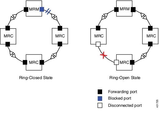
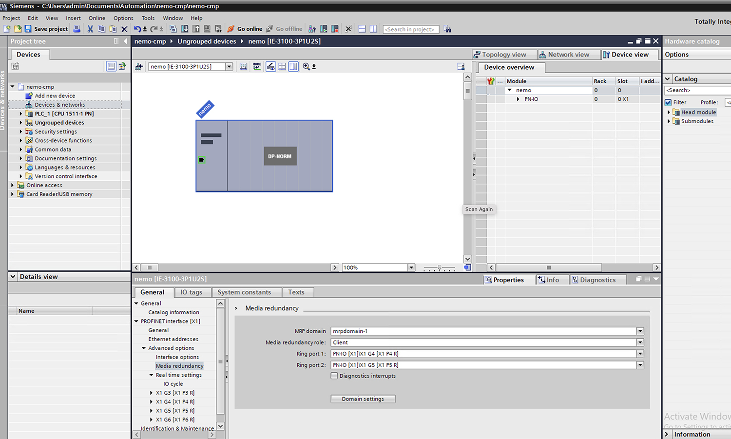
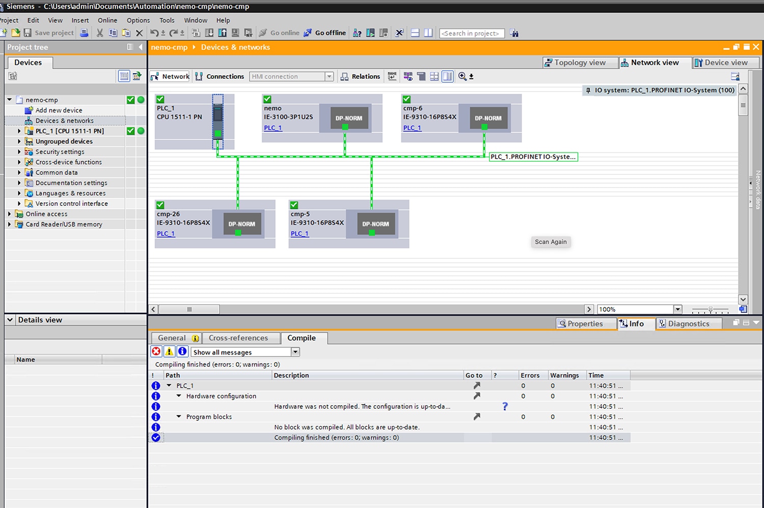
Media Redundancy Protocol
A MRP is a network protocol for industrial automation that ensures fast convergence in ring network topologies.
-
Ensures fast convergence in ring network topologies for industrial automation
-
Operates under the IEC standard 62439-2
-
Supports recovery times of 30 ms, 200 ms, and 500 ms
Supported switches and feature history for MRP
List of Cisco Catalyst IE9300 Rugged Series Switches that support MRP:
-
IE-9310-26S2C-E and IE-9310-26S2C-A
-
IE-9320-26S2C-E and IE-9320-26S2C-A
-
IE-9320-22S2C4X-E and IE-9320-22S2C4X-A
-
IE-9320-24T4X-E and IE-9320-24T4X-A
-
IE-9320-24P4X-E and IE-9320-24P4X-A
-
IE-9320-16P8U4X-E and IE-9320-16P8U4X-A
-
IE-9320-24P4S-E and IE-9320-24P4S-A
-
IE-9310-16P8S4X-E and IE-9310-16P8S4X-A
|
Feature |
Release information |
Feature description |
|---|---|---|
|
Media Redundancy Client |
26.1.1 |
This feature enables the configuration of Cisco switches as MRC within an MRP ring. This allows them to participate in network redundancy and respond to topology changes without acting as the ring manager. This approach enhances network resiliency and simplifies deployment. It also supports rapid failover and compliance with industrial certification requirements. |
|
Enhanced ring convergence profiles for standalone IE9300 switches |
Release 17.18.1 |
From Cisco IOS-XE 17.18.1 onwards, 12 rings of 30ms is also supported on a standalone IE9300 switch. |
|
PTP over MRP |
Release 17.18.1 |
From Cisco IOS-XE 17.18.1 onwards, PTP support over MRP is introduced. |
|
MRP on an IE9300 Stack |
Release 17.17.1 |
From Cisco IOS-XE 17.17.1 onwards, stack support for MRP is introduced. |
|
MRP |
Release 17.13.1 |
From Cisco IOS-XE 17.13.1 onwards, 12 rings of 200 ms or 500 ms convergence profiles are supported on a standalone IE9300 switch. |

 Feedback