VLAN Mapping

VLAN mappings

A VLAN mapping is a Layer 2 feature that translates customer VLAN IDs (VLAN ID assigned by the customer) into service VLAN IDs (VLAN ID assigned by the service provider) on trunk ports connected to your network. The VLAN mapping:

  • enables service providers reuse of VLAN IDs across shared backbones by maintaining traffic isolation, and

  • requires all features on mapped ports must reference the S-VLAN instead of the original C-VLAN.

Typical deployment scenario

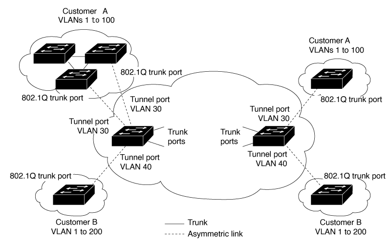
In a typical deployment, service providers want to provide a transparent switching infrastructure where customers' remote switches function as part of the local site. This allows customers to use the same VLAN ID space and run Layer 2 control protocols seamlessly across the provider network. We recommend that service providers do not impose their VLAN IDs on customers.

Service providers internal VLAN assignments might conflict with a customer's VLANs. VLAN mapping solves this by translating customer VLANs into different service provider VLANs while traffic travels through the provider's network.

VLAN mapping operations and behaviors

VLAN mapping is supported on all models of Cisco Catalyst IE9300 Rugged Series Switches with Network Essentials or Network Advantage licenses. Any feature that you configure on a VLAN-mapped port must reference the S-VLAN rather than the original C-VLAN. Service provider’s internal assignments might conflict with a customer’s VLAN. To isolate customer traffic, a service provider could decide to map a specific VLAN into another one while the traffic is in its cloud.

When packets enter a port configured for VLAN mapping, the switch maps the specified C-VLAN to the specified S-VLAN based on the port number and the packet's original C-VLAN. All forwarding operations on the switch are performed using S-VLAN information, not C-VLAN, because the VLAN ID is mapped to the S-VLAN at ingress. When packets exit the port, symmetrical mapping back to the customer C-VLAN occurs automatically.

The VLAN mapping types on trunk port are:


Note


Always configure features on a VLAN-mapped port with the S-VLAN instead of the customer VLAN ID (C-VLAN). One-to-one VLAN mapping is not supported.


VLAN mapping deployment

For example, If Customer A and Customer B use the same VLANs (such as VLAN 10) at multiple sites on different sides of a service provider network, you can map the customer VLAN IDs to unique service provider VLAN IDs (such as VLAN 100 for Customer A, VLAN 200 for Customer B) for packet travel across the backbone. The original customer VLAN IDs are restored at the other side of the service provider backbone for use in the other customer site. Configure the same set of VLAN mappings at customer-connected ports on each side of the service provider network.

Selective Q-in-Q

Selective Q-in-Q is a VLAN mapping feature that tags only specified customer VLANs (C-VLANs) with a service-provider VLAN ID (S-VLAN) at the user-network interface (UNI), so packets traverse the provider network double-tagged while retaining the original customer tag.

  • Maps configured customer VLANs at the UNI to the specified S-VLAN and adds the S-VLAN tag while leaving the C-VLAN tag intact.

  • Drops any packets that do not match the configured customer VLAN list.

  • Removes the S-VLAN tag at egress and forwards the packet with the original customer VLAN ID preserved.

Q-in-Q on a trunk ports

Q-in-Q on trunk ports is a VLAN stacking mode that tags every customer VLAN entering the UNI with the same service-provider VLAN ID (S-VLAN), so all customer traffic crosses the provider cloud double-tagged. The switch removes the S-VLAN tag at egress so the customer receives frames with their original VLAN IDs.

Guidelines for VLAN mapping Selective Q-in-Q and Q-in-Q on trunk port

Guidelines for VLAN mapping

  • By default, no VLAN mapping is configured. Enable VLAN mapping only on the port-channel (EtherChannel) interface, not on individual member ports.

  • If the VLAN mapping is enabled on an EtherChannel, the configuration applies only to the EtherChannel interface.

  • If the VLAN mapping is enabled on an EtherChannel and a conflicting mapping is enabled on a member port, the port is removed from the EtherChannel.

  • Changing a member port’s mode of an EtherChannel from trunk removes it from the EtherChannel bundle.

  • Enable Layer 2 protocol tunneling or insert a BPDU filter for spanning tree to ensure consistent control traffic processing. For configurations, see Layer 2 NAT commands

  • Do not use default or user-configured native VLANs, or reserved VLANs in the 1002 to 1005 range, for VLAN mapping.

  • Private VLAN (PVLAN) is not supported when VLAN mapping is configured.

Guidelines for Selective Q-in-Q

  • Create the S-VLAN and add it to the trunk's allowed VLAN list before enabling Selective Q-n-Q.

  • When Selective Q-n-Q is enabled, Layer 2 protocol tunneling is supported for CDP, STP, LLDP, and VTP.

  • IP routing and IPSG are not supported on Selective Q-n-Q enabled ports.

Guidelines for Q-in-Q on a trunk port

  • Create the S-VLAN and add it to the trunk's allowed VLAN list before enabling Q-n-Q on the trunk port.

  • When QnQ is enabled on a trunk port, Layer 2 protocol tunneling is supported for CDP, STP, LLDP, and VTP.

  • Ingress SPAN, egress SPAN, and RSPAN are supported on trunk ports with Q-n-Q enabled.

  • SPAN filtering can be enabled to monitor only the traffic on the mapped VLAN (S-VLANs).

  • IGMP snooping is not supported on the C-VLAN when Q-n-Q is configured.

Mapping customer VLANs to service-provider VLANs

In multi-tenant environments, different customers often use overlapping VLAN IDs across geographically distributed sites. When these sites connect through a service-provider network, VLAN ID conflicts can occur. VLAN mapping resolves this by translating customer VLAN IDs to unique service-provider VLAN IDs as traffic traverses the backbone.

Summary

The key components in the VLAN mapping process are:

  • Customer sites: Network locations that use customer-specific VLAN IDs.

  • Service-provider network: The backbone infrastructure that transports traffic between customer sites.

  • Customer-connected ports: Edge interfaces on the service-provider network where VLAN mapping occurs.

The VLAN mapping process translates customer VLAN IDs to service-provider VLAN IDs at ingress, transports the traffic across the backbone using provider VLANs, and restores the original customer VLAN IDs at egress to maintain connectivity between customer sites.

Workflow

Figure 1. QnQ topology

These stages describe how VLAN mapping works across a service-provider network

    • Traffic from Customer A enters the service-provider network through a customer-connected port at Site 1.
    • The ingress port maps the customer VLAN ID to a unique service-provider VLAN ID.
    • The packet traverses the service-provider backbone using the mapped service-provider VLAN ID.
    • At the egress customer-connected port at Site 2, the service-provider VLAN ID is mapped back to the original customer VLAN ID.
    • The traffic reaches Customer A's destination site with the original VLAN ID intact.
    • The same mapping process occurs for Customer B's traffic, using a different set of service-provider VLAN IDs to prevent conflicts.

Result

VLAN mapping ensures that multiple customers can use identical VLAN IDs across distributed sites without conflicts. The service-provider network maintains traffic isolation while transparently preserving customer VLAN configurations, enabling scalable multi-tenant connectivity.

Configure selective Q-in-Q on a trunk port

You can enable selective Q-in-Q VLAN mapping on a trunk port to manage and differentiate customer and service provider VLAN traffic.

You can map specific customer VLAN IDs (C-VLANs) to provider VLAN IDs (S-VLANs) on a trunk port using selective Q-in-Q, which enables flexible service provider isolation and delivery for multiple customers.


Note


You cannot configure both one-to-one mapping and selective Q-in-Q on the same interface.


Before you begin

Ensure you have identified the interface connected to the service provider network.

  • Review your desired C-VLAN and S-VLAN mapping requirements.

  • You cannot configure one-to-one mapping and selective Q-in-Q on the same interface.

Perform these steps to configure selective Q-in-Q mapping.

Procedure


Step 1

Configuration

  1. Use the enable command to enter privileged EXEC mode.

    Example:

    Switch> enable

    If prompted, enter your password.

  2. Use the configure terminal command to enter global configuration mode.

    Example:

    Switch# configure terminal
  3. Use the interface interface-id command to enter interface configuration mode for the interface connected to the service provider network.

    Example:

    Switch(config)# interface gigabitethernet1/0/1

    interface-id : Enter a physical interface or an EtherChannel port channel.

  4. Use the switchport mode trunk command to configure the interface as a trunk port.

    Example:

    Switch(config-if)# switchport mode trunk
  5. Use the switchport vlan mapping vlan-id dot1q-tunnel outer vlan-id command to enter the VLAN IDs to be mapped.

    Example:

    Switch(config-if)# switchport vlan mapping 16 dot1q-tunnel 64
    • vlan-id : The customer VLAN ID (C-VLAN) entering the switch from the customer network. The range is from 1 to 4094. Enter a string of VLAN IDs.

    • outer vlan-id : The outer VLAN ID (S-VLAN) of the service provider network. The range is from 1 to 4094.

    Use the no form of this command to remove the VLAN mapping configuration. Entering the no switchport vlan mapping all command deletes all mapping configurations.

  6. Use the switchport vlan mapping default dot1q-tunnel vlan-id command to specify that all unmapped packets on the port are forwarded with the specified S-VLAN.

    Example:

    Switch(config-if)# switchport vlan mapping default dot1q-tunnel 22

    By default, packets that do not match the mapped VLANs are dropped.

    The system forwards the untagged traffic.

  7. Use the exit command to return to global configuration mode.

    Example:

    Switch(config-if)# exit
  8. Use the spanning-tree bpdufilter enable command to insert a BPDU filter for spanning tree.

    Example:

    Switch(config)# spanning-tree bpdufilter enable

    Note


    To process control traffic consistently, you can enable Layer 2 protocol tunneling or insert a BPDU filter for spanning tree.

  9. Use the end command to return to privileged EXEC mode.

    Example:

    Switch(config)# end

Step 2

Verification

  1. (Optional) Use the show interfaces interface-id vlan mapping command to verify the configuration.

    Example:

    Switch# show interfaces gigabitethernet1/0/1 vlan mapping
  2. (Optional) Use the copy running-config startup-config command to save your entries in the configuration file.

    Example:

    Switch# copy running-config startup-config

Configure Q-in-Q on a trunk port

You can configure Q-in-Q VLAN mapping on a trunk port to encapsulate customer VLAN packets with a designated service provider VLAN tag.

Use this task to configure selective Q-in-Q VLAN mapping on a trunk interface, enabling all customer VLAN packets to be encapsulated and carried with a designated provider VLAN tag. Service provider networks typically require this to separate customer traffic and apply unified service policies.

Before you begin

Ensure the Service Provider VLAN ID (S-VLAN) to be used for mapping.

Perform these steps to configure Q-in-Q on a trunk port.

Procedure


Step 1

Use the enable command to enter privileged EXEC mode.

Example:

Switch> enable

Enter your password if prompted.

Step 2

Use the configure terminal command to enter global configuration mode.

Example:

Switch# configure terminal

Step 3

Use the interface interface-id command to enter interface configuration mode for the interface connected to the service provider network.

Example:

Switch(config)# interface gigabitethernet1/0/1

You can enter either a physical interface or an EtherChannel port channel.

Step 4

Use the switchport mode trunk command to configure the interface as a trunk port.

Example:

Switch(config-if)# switchport mode trunk

Step 5

Use the switchport vlan mapping default dot1q-tunnel vlan-id command to specify that all unmapped C-VLAN packets on the port are forwarded with the specified S-VLAN.

Example:

Switch(config-if)# switchport vlan mapping default dot1q-tunnel 16

Step 6

Use the exit command to exit the interface configuration mode.

Example:

Switch(config-if)# exit

Step 7

Use the spanning-tree bpdufilter enable command to insert a BPDU filter for spanning tree.

Example:

Switch(config)# spanning-tree bpdufilter enable

Note


To process control traffic consistently, either enable Layer 2 protocol tunneling (recommended) or insert a BPDU filter for spanning tree.

Step 8

Use the end command to return to privileged EXEC mode.

Example:

Switch(config)# end

Step 9

(Optional) Use the show interfaces interface-id vlan mapping command to verify the configuration.

Example:

Switch# show interfaces gigabitethernet1/0/1 vlan mapping

Use the copy running-config startup-config command to save your entries in the configuration file.


Configure selective Q-in-Q mapping on the port

Map specific customer VLAN (C-VLAN) IDs to a service provider VLAN (S-VLAN) ID on a port.

Selective Q-in-Q mapping allows you to tunnel specific traffic through the switch. By default, the system drops traffic from any VLAN ID not explicitly mapped, unless you configure a default S-VLAN ID to forward the remaining traffic.

Before you begin

Identify the C-VLAN range and the target S-VLAN ID for the tunnel.

Perform these steps to configure selective Q-in-Q mapping.

Procedure


Step 1

Use the configure terminal command to enter global configuration mode.

Example:

Switch# configure terminal

Step 2

Use the interface GigabitEthernet <interface_id> command to enter interface configuration mode for the target port.

Example:

Switch(config)# interface GigabitEthernet 1/0/1

Step 3

Use the switchport vlan mapping 2-5 dot1q-tunnel <channel_id> command to map a range of C-VLAN IDs to a specific S-VLAN ID to enable selective Q-in-Q.

Example:

Switch(config-if)# switchport vlan mapping 2-5 dot1q-tunnel 100

Step 4

(Optional) Use the switchport vlan mapping 2-5 default dot1q-tunnel <channel_id> command to configure a default S-VLAN ID to forward traffic from all other VLANs.

Example:

Switch(config-if)# switchport vlan mapping default dot1q-tunnel 100

Note


If you omit this step, the system drops all traffic that does not match the range specified in Step 3.

Step 5

Use the exit command to return to privileged EXEC mode.

Example:

Switch(config-if)# exit

Step 6

(Optional) Use the show vlan mapping command to verify the VLAN mapping configuration on the interface.

Example:

Switch(config-if)# exit
Total no of vlan mappings configured: 5
Interface Hu1/0/50:
VLANs on wire                    Translated VLAN     Operation
------------------------------   ---------------     --------------
2-5                                   100            selective QinQ
*                                     200            default Q

Feature History for VLAN Mapping

This table provides release and related information for features explained in this chapter. These features are available on all releases subsequent to the one they were introduced in, unless noted otherwise.

Release

Feature

Feature Information

Cisco IOS XE 17.13.1

Selective QnQ

Support for features was introduced.

QnQ on a trunk port