Layer 2 network address translations
Layer 2 network address translation (L2 NAT) enables communication between private and public subnets by assigning unique public IP addresses to private endpoints. L2NAT:
-
translates IPv4 addresses in both directions: public to private and private to public using a hardware-based table, and
-
assigns a unique public IP address to a private endpoint. This assignment enables communication across private and public subnets. A NAT-enabled device maintains the public alias in hardware for this service.
-
supports wire-speed performance and multiple Virtual Local Area Networks (VLAN)s for enhanced network segmentation.
Layer 2 NAT operation and configuration
Layer 2 NAT uses a table to translate IPv4 addresses both public-to-private and private-to-public at line rate. It is a hardware-based implementation that provides wire-speed performance and supports multiple VLANs through the NAT boundary for enhanced network segmentation.
For large numbers of nodes, subnet-based translations allow all devices in a subnet to be translated with a single command, reducing the number of required Layer 2 NAT rules. The switch has limits on the number of Layer-₹2 NAT rules, so using subnet-based rules optimizes resource usage.
-
Layer 2 NAT is implemented on a NAT-enabled device, which maintains the public alias in hardware.
-
Subnet-based translations save on Layer 2 NAT rules by allowing multiple end devices to be translated with a single rule.
-
Interfaces can support multiple Layer 2 NAT instance definitions for different VLAN subnets.
Comparison of address translation approaches:
|
Attributes |
Host-based NAT |
Subnet-based NAT |
|---|---|---|
|
Translation granularity |
Per device |
Per subnet |
|
Rule efficiency |
Requires many rules |
Fewer rules needed |
 Note |
TIP: Use subnet-based translation rules to optimize Layer 2 NAT scalability and reduce configuration complexity. |
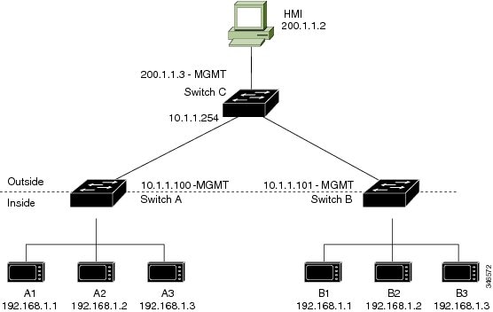
How inside-outside address translation works
This process describes how subnet-based layer 2 NAT rules enable efficient address translation for multiple devices across overlapping internal address spaces. The NAT device allocates unique outside subnets, creates translation rules, and translates addresses during communication to resolve duplicate IP address conflicts while optimizing rule usage.
Summary
The key components involved in inside-outside address translation are:
-
Inside Network 1: Uses 192.168.1.x addresses.
-
Inside Network 2: Uses 192.168.1.x addresses (duplicate address space).
-
Outside Network: Provides unique address spaces for each internal network
-
NAT device: Performs address translation using hardware-based tables.
Workflow
This image shows the inside-outside address translation process.
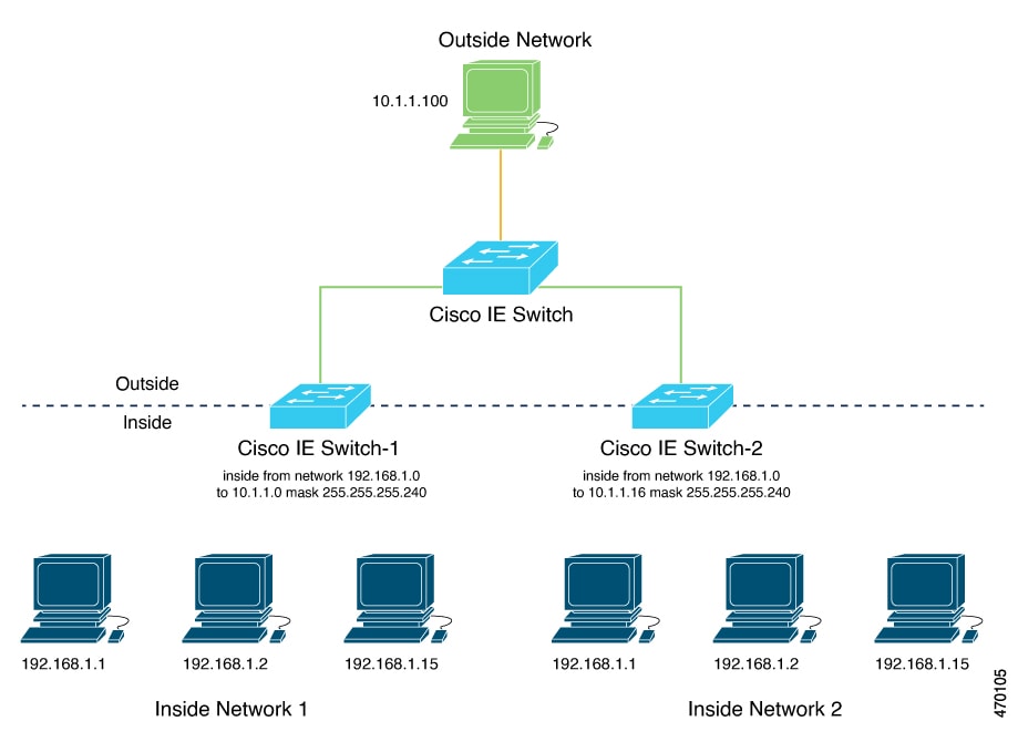
These stages describe how inside-outside address translation works:
-
The NAT device allocates unique outside subnet addresses to each internal network.
- Inside network 1 receives the 10.1.1.0/28 subnet with usable addresses from 10.1.1.1 through 10.1.1.14.
- Inside network 2 receives the 10.1.1.16/28 subnet with usable addresses from 10.1.1.17 through 10.1.1.30.
- The administrator creates subnet-based translation rules using a single network command for each subnet. A single network command translates all devices within a subnet, reducing the total number of layer 2 NAT rules required.
- The NAT device translates addresses when devices communicate with external networks. Each device from either internal network uses its translated outside address for external communication. This approach resolves duplicate IP address conflicts while optimizing NAT rule usage within the switch's hardware limitations.
Result
Subnet-based translations enable efficient layer 2 NAT deployment by allowing multiple devices to share a single translation rule, reducing hardware resource consumption while maintaining network segmentation across overlapping address spaces.
Enabling inside-to-outside communications
This process enables communication between an inside device (A1) and an outside device (LC) by translating addresses and facilitating ARP exchanges through the Cisco switch.
In this example, A1 must communicate with a logic controller (LC) that is directly connected to the uplink port. A Layer 2 NAT instance is configured to provide an address for A1 on the outside network (10.1.1.1) and an address for the LC on the inside network (192.168.1.250).
Note |
The management interface of the switch must be on a different VLAN from the inside network 192.168.1.x. |
Summary
-
A1: Initiates communication from the inside network.
-
Logic Controller (LC): Receives requests and responds from the outside network.
-
Cisco Switch A: Performs Layer 2 NAT address fixup for Address Resolution Protocol (ARP) requests and responses.
Workflow
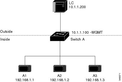
These stages describe the ARP and address translation process for inside-to-outside communications.
-
A1 sends an ARP request to the logic controller (LC) on the inside network.
- Source Address: 192.168.1.1
- Destination Address: 192.168.1.250
-
Cisco Switch A performs Layer 2 NAT fixup on the ARP request.
- Source Address: 10.1.1.1
- Destination Address: 10.1.1.200
-
LC receives the ARP request and learns the MAC address of 10.1.1.1.
- LC updates its ARP table with the MAC address for 10.1.1.1.
-
LC sends an ARP response to A1 via the Cisco switch.
- Source Address: 10.1.1.200
- Destination Address: 10.1.1.1
-
Cisco Switch A performs Layer 2 NAT fixup on the ARP response.
- Source Address: 192.168.1.250
- Destination Address: 192.168.1.1
-
A1 learns the MAC address for 192.168.1.250, and communication starts.
- A1 can now communicate with the LC using the translated addresses.
Configure inside-to-outside communications
You can configure inside-to-outside communications by creating a Layer 2 NAT instance, adding two translation entries, and applying the instance to the interface. ARP fixups are enabled by default.
Before you begin
Ensure that you read and understand Enabling inside-to-outside communications .
Procedure
|
Step 1 |
Use the configure command to enter configuration mode. Example: |
||
|
Step 2 |
Use the l2nat instance A-LC command to create a new Layer 2 NAT instance called A-LC. Example: |
||
|
Step 3 |
Use the inside from host ip_address-1 to ip_address-2 command to translate A1’s inside address to an outside address. Example: |
||
|
Step 4 |
Use the inside from host ip_address-1 to ip_address-2 command to translate A2’s inside address to an outside address. Example: |
||
|
Step 5 |
Use the inside from host ip_address-1 to ip_address-2 command to translate A3’s inside address to an outside address. Example: |
||
|
Step 6 |
Use the outside from host ip_address-1 to ip_address-2 command to translate the LC outside address to an inside address. Example: |
||
|
Step 7 |
Use the exit command to exit config-l2nat mode. Example: |
||
|
Step 8 |
Use the interface Gi1/1 command to access interface configuration mode for the uplink port. Example: |
||
|
Step 9 |
Use the l2nat A-LC command to apply this Layer 2 NAT instance to the native VLAN on this interface. Example:
Use the end command to return to privileged EXEC mode. |
How Layer 2 NAT works
This process demonstrates how Layer 2 NAT translates addresses between sensors on a 192.168.1.x internal network and a line controller on a 10.1.1.x external network.
Summary
The key components involved in the process are:
-
Sensor: Initiates communication by sending packets from the internal network (for example, a device with IP address 192.168.1.1).
-
Layer 2 NAT device: Sits between the internal and external networks, translating IP addresses in both outbound and inbound directions to enable communication.
-
Line controller: Receives and responds to packets on the external network (for example, a device with IP address 10.1.1.100).
Workflow
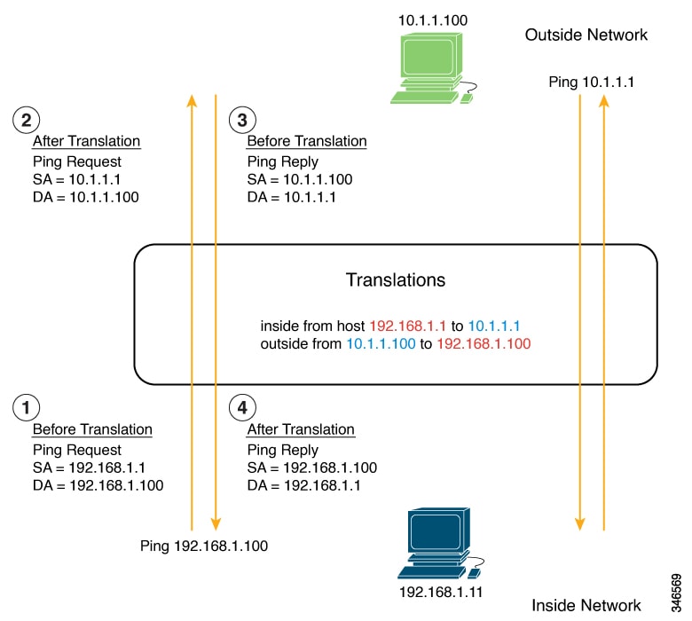
-
Packet initiation
- The sensor at IP address 192.168.1.1 sends a ping request to the line controller using the inside address 192.168.1.100.
-
Outbound translation
Before the packet leaves the internal network, Layer 2 NAT translates:
- Source address (SA): from 192.168.1.1 to 10.1.1.1
- Destination address (DA): from 192.168.1.100 to 10.1.1.100
- Response initiation The line controller receives the translated packet and sends a ping reply to 10.1.1.1.
-
Inbound translation
When the reply packet enters the internal network, Layer 2 NAT translates:
- Source address: from 10.1.1.100 to 192.168.1.100
- Destination address: from 10.1.1.1 to 192.168.1.1
Result
Bidirectional communication is established between devices on different IP address spaces through NAT translation.
How Layer 2 NAT on switches works
This process describes how Layer 2 NAT centralizes address translation at the aggregation Layer, enabling efficient address management and inter-VLAN communication across large-scale networks. The aggregation switch performs NAT translation using subnet-based rules, while downstream access-Layer switches forward traffic without performing translation.
Summary
NAT on switches centralizes network address translation at the aggregation Layer, enabling efficient address management and inter-VLAN communication while keeping downstream access-Layer switches unaware of NAT.
The key components involved in centralized NAT operation are:
-
Aggregation switch: Performs Layer 2 NAT translation at wire speed for multiple VLANs and maintains translation tables for bidirectional address mapping.
-
Router: Acts as Layer 3 gateway for all subnets and VLANs, with its gateway addresses translated by the NAT device.
-
Access-Layer switches: Forward traffic to the aggregation switch without performing NAT and rely entirely on the upstream aggregation switch for address translation.
The NAT on switch process involves configuring subnet-based NAT instances using the network command, which enables translation of multiple devices within a subnet using a single rule. The aggregation switch applies these instances to trunk interfaces, performs translation based on VLAN membership, and forwards translated packets through the uplink. This centralized approach optimizes hardware resources by reducing the number of NAT translation records required.
Workflow
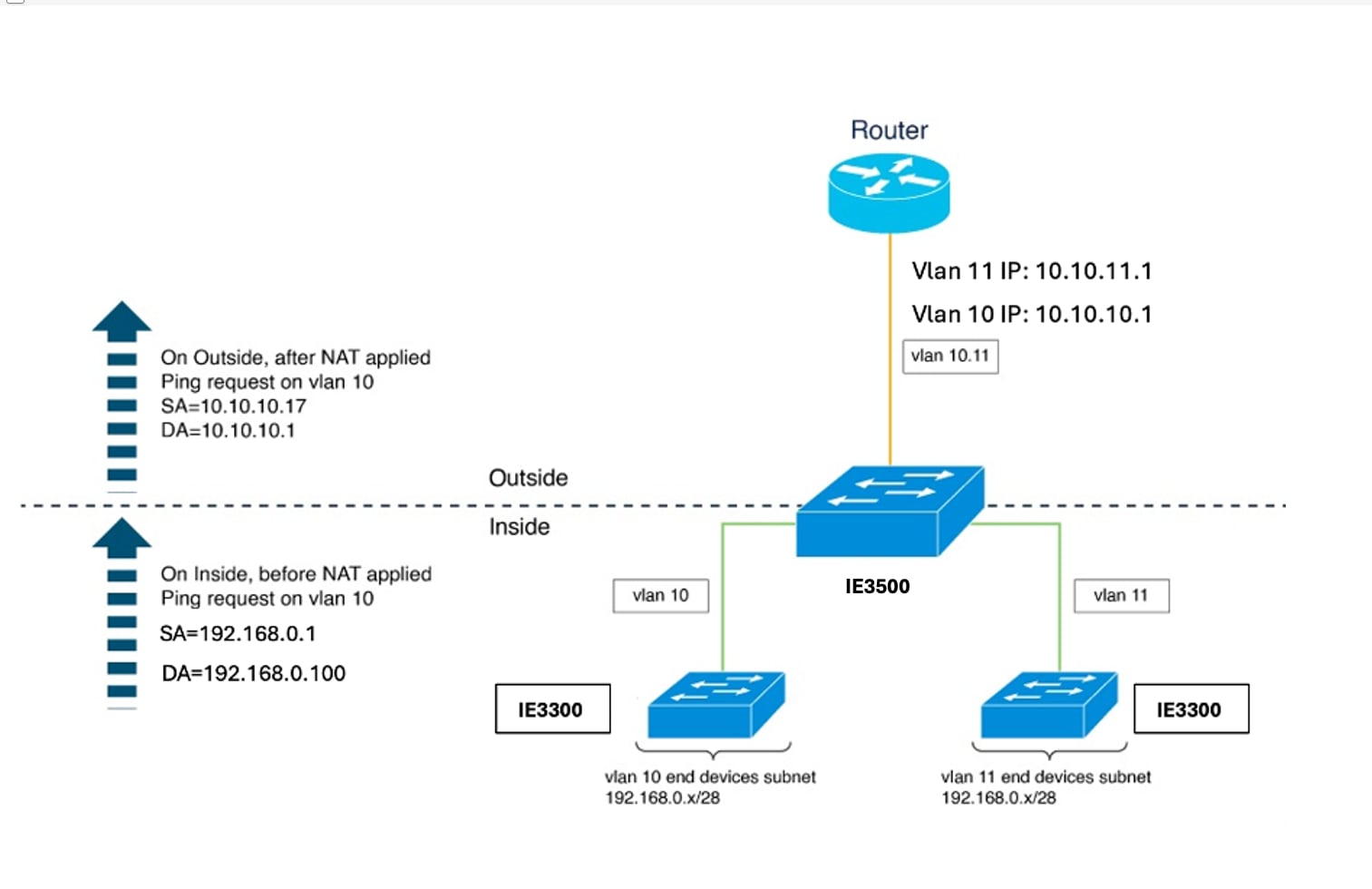
These stages describe how Layer 2 NAT on switches works:
- The network administrator configures subnet-based NAT instances for each VLAN. The administrator creates NAT instances for VLAN 10 and VLAN 11 using the network command to define translation rules: The network command translates an entire subnet of hosts with a single rule, significantly reducing Layer 2 NAT translation records. The /28 subnet configuration covers addresses where the last byte ranges from 16 to 31.
- The network administrator configures gateway translations for routing. The administrator defines outside host translation for the router gateway to enable proper routing between networks: The gateway for each VLAN uses the router address with the last byte ending in .1.
- The network administrator applies NAT instances to the uplink interface on the aggregation switch. The administrator attaches both NAT instances to the Gi1/1 uplink interface operating in trunk mode: Interfaces can support multiple Layer 2 NAT instance definitions simultaneously. The switch uses VLAN tags to determine which NAT instance to apply for incoming packets.
- The access switches forward VLAN-tagged packets to the aggregation switch. Access switches receive packets on downstream ports from end devices and forward them upstream to the aggregation switch. Packets arrive tagged with their respective VLAN identifiers (VLAN 10 or VLAN 11). The access-Layer switches do not perform any NAT operations.
-
The aggregation switch translates addresses and forwards packets through the uplink.
The aggregation switch processes packets based on their VLAN tag and applies the appropriate NAT instance:
For outbound traffic:
- Source addresses from the inside network (192.168.0.x) translate to addresses in the appropriate outside subnet (10.10.10.x or 10.10.11.x).
- Destination addresses translate according to outside host translation rules.
- Source addresses from the outside network translate to inside addresses.
- Destination addresses translate back to original inside addresses.
- The aggregation switch translates router gateway addresses bidirectionally. When devices communicate with the gateway, the aggregation switch translates the gateway address. For configuration, refer to the Configure NAT on switch commands in the Layer 2 NAT commands section.
Result
Centralized NAT at the aggregation switch enables efficient, scalable address translation across multiple VLANs with minimal NAT rule records. This approach streamlines network management, reduces configuration and maintenance complexity on access-Layer switches, and optimizes hardware resource utilization within the switch's NAT rule capacity limitations.
 Feedback