Layer 3 Network Address Translation

Network address translations

Network address translation (NAT) is an IP address conservation method that:

  • translates private, unregistered IP addresses into global routable addresses before packets are forwarded to another network

  • operates on a device that connects two networks

  • hides internal network addresses to improve security, and

  • can be configured to advertise only one address for the entire network to the outside world, enhancing both security and address conservation.

  • provides internet access for internal users and external access to internal servers.

  • implemented in remote-access environments.

Key characteristics and hardware support for NAT

The Cisco Catalyst IE9300 Rugged Series Switch supports stacking, and NAT is supported on a stack set-up.

The maximum number of bidirectional NAT flows supported in hardware is limited to 240.

Limitations of network address translation

Be aware of the following NAT limitations when configuring your network.

  • Hardware data plane limitations

    • Translation of Internet Control Message Protocol (ICMP) packets.

    • Translation of packets that require application layer gateway (ALG) processing.

    • Packets that require both inside and outside translation.

  • Session and resource limitations

    • The maximum number of sessions that can be translated and forwarded in the hardware is limited to 240. Additional flows that require translation are handled in software at reduced throughput.

    • A configured NAT rule might fail to program into hardware due to resource constraints, resulting in packets being forwarded without translation.

    • Each translation consumes two entries in TCAM.

  • Protocol support limitations

    • ALG support is limited to FTP, TFTP, and ICMP protocols. TCP SYN, TCP FIN, and TCP RST packets are processed as ALG traffic.

    • NAT does not support translation of fragmented packets.

    • NAT does not support multicast packets.

    • Dynamically created NAT flows age out after a period of inactivity.

  • Feature compatibility restrictions

    • Policy Based Routing (PBR) and NAT are not supported on the same interface. PBR and NAT work together only if they are configured on different interfaces.

    • Equal-cost multi-path routing (ECMP) is not supported with NAT.

    • NAT is not supported over GRE tunnels.

    • Inter-VRF NAT and Intra-VRF NAT are not supported.

  • Bidirectional Forwarding Detection (BFD) and NAT interaction

    • BFD sessions may fail if they are configured to operate using the same address that is used for dynamic NAT. To prevent address conflicts when configuring both BFD and dynamic NAT on the same device, ensure the BFD session address does not overlap with any NAT pool addresses. If you must configure BFD and dynamic NAT overloading on the same interface, deploy a pool-based dynamic NAT overload configuration. Ensure that you do not use the chosen NAT pool address for BFD even in this scenario.

  • Stateful switchover limitations

    • NAT does not support Stateful Switchover (SSO). Dynamically created NAT states are not synchronized between the active and standby devices.

    • When both ingress and egress NAT interfaces are on the same switch, hardware NAT entries in TCAM may go out of sync on the remote or standby switch after SSO. When AOT is enabled, this can occur on the remote switch after NAT timeout.

  • Flexible NetFlow and NAT interaction

    • When Flexible NetFlow and Network Address Translation (NAT) are configured on an interface:

      • Flexible NetFlow displays and exports actual flow details, but not translated flow details

      • ALG flow details are not part of the exported actual flow details

      • If ALG traffic is translated through CPU, Flexible NetFlow displays and exports the translated flow details for ALG traffic

  • ACL and configuration restrictions

    • Explicit deny access control entry (ACE) in NAT ACL is not supported. Only explicit permit ACE is supported.

    • NETCONF configuration fails if it is configured to use the same IP address used for configuring NAT using interface overload.

NAT configuration recommendations and types

Ensure that the local addresses specified in static and dynamic NAT rules do not overlap.

Recommendations for NAT configuration

  • Ensure that the local addresses specified in static and dynamic NAT rules do not overlap. If overlap is possible, configure the ACL associated with the dynamic rule to exclude the corresponding addresses used by the static rule. Similarly, ensure there is no overlap between the global addresses.

  • Do not employ loose filtering such as permit ip any any in an ACL associated with a NAT rule to avoid packets translation.

  • Do not share an address pool across multiple NAT rules.

  • Do not define the same inside global address in both static NAT configuration and dynamic pool configuration.

  • Carefully evaluate the impact before modifying the default timeout values associated with NAT. Small timeout values could result in high CPU usage.

  • Avoid manually clearing NAT translation entries unless absolutely necessary. Manually clearing translation entries could result in the disruption of active application sessions.

  • Use dedicated interface(s) for NAT traffic when Application-Level Gateway (ALG) protocols are in use as they are punted to CPU. For all other types of traffic that does not require NAT translation, use different interface(s).

Types of NAT

You can configure NAT such that it advertises only a single address for your entire network to the outside world. The configuration effectively hides the internal network from the world, giving you some additional security.

The types of NAT include:

  • Static address translation (static NAT): Allows one-to-one mapping between local and global addresses.

  • Dynamic address translation (dynamic NAT): Maps unregistered IP addresses to registered IP addresses from a pool of registered IP addresses.

  • Overloading or Port Address Translation (PAT): Maps multiple unregistered IP addresses to a single registered IP address (many to one) using different Layer 4 ports. This method is also known as Port Address Translation (PAT). By using overloading, thousands of users can be connected to the Internet by using only one real global IP address.

Benefits of NAT

NAT provide these advantages for your network:

  • IP address conservation: NAT maps internal addresses to a small range of registered Class C addresses to resolve IP address scarcity.

  • Enhanced security: NAT hides internal IP addresses—including already registered internal addresses—from external entities to prevent direct attacks on internal hosts.

  • Addressing flexibility: You can expand internal Class A addressing, which is drawn from the reserve pool of the Internet Assigned Numbers Authority (IANA), without changing addresses at the LAN or internet interface.

  • Simplified configuration: You can implement NAT on a few exit devices without changing other devices in the network.

  • Device compatibility: NAT is designed for use on a variety of devices for IP address simplification and conservation.

IP address depletion resolution: NAT allows organizations with existing networks to access the internet without acquiring registered IP addresses for every host. Sites that do not yet possess Network Information Center (NIC)-registered IP addresses must acquire IP addresses. If a site has more than 254 clients, NAT resolves the scarcity of Class B addresses by mapping internal addresses to available Class C addresses.

Network security: NAT secures the network by hiding internal client addresses—including registered internal addresses—from external entities. This prevents hackers from identifying and attacking specific internal hosts.

Implementation flexibility: Cisco software performs NAT selectively or dynamically. This allows you to use RFC 1918 addresses or registered addresses and select specific internal hosts for translation. You can configure NAT on a few exit devices without modifying other devices in the network.

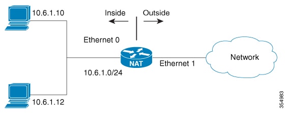
Connecting to the internet with limited global IP addresses

Use NAT to enable internet connectivity when only a few of your hosts have globally unique IP addresses.

Configure NAT on the border device between your internal network and the internet. NAT translates your internal addresses to globally unique IP addresses before forwarding packets to the internet.

This approach works when few internal hosts communicate externally at the same time. NAT translates only active connection addresses and reuses these global addresses as needed.


Note


Translate internal addresses using NAT instead of changing them manually, which reduces configuration effort.


Use cases for network address translations

You can use network address translations in the following scenarios:

  • Internet connectivity: When only a few hosts in your internal network require a globally unique IP address to communicate with the internet simultaneously.

  • Network renumbering: When you need to change internal addresses but prefer to translate them using NAT rather than manually reconfiguring every host.

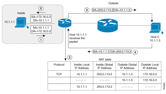
  • Overlapping networks: When you connect two networks that use the same private IP address space (such as 10.1.1.x) and need to translate the addresses to ensure connectivity.

Static and dynamic translations

This table contrasts the two primary methods of source address translation.

Table 1. Static and dynamic translations
Static translation Dynamic translation
Establishes a permanent one-to-one mapping between an inside local address and an inside global address. Establishes a temporary mapping between an inside local address and a pool of global addresses at run-time.
Used when an internal host (such as a mail server) must be accessible from the outside using a fixed address. Used when multiple users on a private network need to access the internet periodically.
The mapping is manually configured and does not time out. The mapping is created dynamically and is released back to the pool after a period of inactivity.

How network address translation works

NAT operates on devices positioned between internal and external networks. In typical deployments, NAT is configured on exit devices that connect stub domains to backbone networks.

Summary

The key components involved in the NAT process are:

  • NAT-enabled device: A router or firewall configured with NAT that has at least one interface connected to the inside network and one interface connected to the outside network. Multiple inside networks and multiple exit points to outside networks can be connected to the NAT device.

  • Inside network: The private network using local addresses that require translation.

  • Outside network: The public network using globally unique addresses.

The NAT process translates local addresses to global addresses for outbound traffic and translates global addresses back to local addresses for inbound traffic. Translation and forwarding are performed in the hardware switching plane to improve throughput performance.

When address allocation fails, the device drops packets and sends an Internet Control Message Protocol (ICMP) host unreachable packet to the destination to maintain network integrity.

Workflow

Figure 1. NAT
  1. Outbound packet processing: When a packet leaves the domain, the NAT-enabled device translates the locally significant source address into a globally unique address.

  2. Inbound packet processing: When a packet enters the domain, the NAT-enabled device translates the globally unique destination address into a local address.

  3. Address allocation handling:

    Table 2. When the NAT device...

    Then the device...

    And...

    successfully allocates an address

    translates the packet

    cannot allocate an address because it has run out of available addresses

    drops the packet

Translation and forwarding are performed in the hardware switching plane, improving the overall throughput performance.

Result


Note


Multiple inside networks can be connected to the device. Similarly, multiple exit points from the device towards outside networks might exist.

For performance details, see Performance and scale numbers for NAT.

NAT types and addresses

NAT inside and outside addresses are classifications that:

  • define the scope and direction of address translation in a NAT-enabled network.

  • allow hosts in outside networks to be subject to translation, and

  • enable bidirectional translation.

Address types in NAT networks

When you configure NAT, hosts use two types of address spaces:

  • Local address space: The internal addresses used within the network.

  • Global address space: The addresses that appear to entities outside the network.

Outside networks: Outside addresses represent the external networks to which the stub network connects. These networks are not under the control of your organization. Both inside and outside networks can contain local and global addresses.

NAT address definitions:

  • Inside local address: An IP address assigned to a host on the inside network. The address is probably not a routable IP address assigned by NIC or service provider.

  • Inside global address: A global routable IP address (assigned by the NIC or service provider) that represents one or more inside local IP addresses to the outside world.

  • Outside local address: The IP address of an outside host as it appears to the inside network. Not necessarily a routable IP address, it is allocated from the address space that is routable on the inside.

  • Outside global address: The IP address assigned to a host on the outside network by the owner of the host. The address is allocated from a globally routable address or network space.

NAT translation types:

  • Inside source address translation: Translates an inside local address to inside global address.

  • Outside source address translation: Translates the outside global address to outside local address.

  • Static port translation: Translates the IP address and port number of an inside/outside local address to the IP address and port number of the corresponding inside/outside global address.

  • Static translation of a given subnet: Translates a specified range of subnets of an inside/outside local address to the corresponding inside/outside global address.

NAT entry types:

  • Half entry: Represents a mapping between the local and global address or ports and is maintained in the translation database of NAT module. A half entry may be created statically or dynamically based on the configured NAT rule.

    Full entry (or flow entry): Represents a unique flow corresponding to a given session. In addition to the local to global mapping, it also maintains the destination information which fully qualifies the given flow. A full entry is always created dynamically and maintained in the translation database of NAT module.

Inside source address translations

An inside source address translation is a translation method that converts an unregistered internal IP address into a globally unique IP address before a packet leaves the network. This method allows internal hosts to communicate with external networks while maintaining a specific identity. This translation:

  • converts unregistered internal IP addresses to globally unique IP addresses.

  • enables internal hosts to communicate with external networks.

  • maintains a specific identity for internal hosts during communication.

Types of inside source address translations

Inside source address translations can be implemented using these translation methods.

  • Static translations : A one-to-one mapping method that associates an inside local address with a fixed inside global address. Use this method to ensure that internal hosts remain accessible from the outside network using a consistent, permanent address. Static translation can be enabled by configuring a static NAT rule. For more details, see Configure static translation of inside source addresses .

  • Dynamic translations : Maps inside local addresses to a pool of global addresses at run-time. Dynamic translation can be enabled by configuring a dynamic NAT rule, and the mapping is established based on the result of the evaluation of the configured rule at run-time. Use standard or extended access control lists (ACLs) to identify local addresses and specify global addresses using an address pool or an interface. This method allows multiple users to share internet access by releasing addresses back to the pool after use. For more details, see Configure dynamic translation of inside source addresses .

How inside source address translation works

NAT enables devices within a private network to communicate with external networks by translating private IP addresses to globally routable addresses. Inside source address translation specifically translates the source IP address of packets originating from inside the network as they exit to outside networks.

Summary

The key components involved in inside source address translation are:

  • Inside local address: The private IP address assigned to a host on the inside network.

  • Inside global address: The globally routable IP address to which the inside local address is translated.

  • NAT module: The component that intercepts packets and performs address translation based on configured rules.

  • Translation database: The repository where NAT maintains flow entries for active translations.

The inside source address translation process maps inside local addresses to inside global addresses using either static one-to-one mappings or dynamic mappings from address pools, translates outbound packets, maintains flow entries for bidirectional communication, and translates return traffic back to inside local addresses.

Workflow

Figure 2. NAT Inside Source Translation

These stages describe how inside source address translation works.

  1. The user at host 10.1.1.1 opens a connection to Host B in the outside network.
  2. The NAT module intercepts the corresponding packet and attempts to translate it.
  3. The NAT module evaluates the packet against configured translation rules.
    When the packet... Then...

    matches a static translation rule

    the NAT module translates the packet to the corresponding inside global address.

    matches a dynamic translation rule and an inside global address is available

    the NAT module translates the packet to an inside global address from the configured pool.

    matches a dynamic translation rule but no inside global address is available

    the NAT module drops the packet.

    does not match any translation rule

    the packet is forwarded without address translation.

  4. The NAT module inserts a fully qualified flow entry for the translated packet into its translation database for fast bidirectional translation.
  5. The device replaces the inside local source address (10.1.1.1) with the inside global address (203.0.113.2) and forwards the packet.
  6. Host B receives the packet and responds using the inside global IP destination address 203.0.113.2.
  7. The NAT module intercepts the response packet destined to the inside global address and translates it back to the corresponding inside local address using the flow entry in the translation database.
  8. Host 10.1.1.1 receives the packet with its original inside local address and continues the conversation.

Result

Inside source address translation enables hosts on private networks to communicate with external networks using globally routable addresses while maintaining bidirectional connectivity through dynamic flow entries in the translation database.

Configure static translation of inside source addresses

You can configure static translation of inside source addresses to enable one-to-one mapping between an inside local address and an inside global address. This allows a host on the inside to be accessible from the outside using a fixed address.

Procedure

Step 1

Static translation

  1. Use the enable command to enter privileged EXEC mode.

    Example:
    Switch> enable

    Enter your password if prompted.

  2. Use the configure terminal command to enters global configuration mode.

    Example:
    Switch# configure terminal
  3. Use any of these commands as per the requirement:

  • Use the ip nat inside source static local-ip global-ip command to establish a static translation between an inside local address and an inside global address.
    Switch(config)# ip nat inside source static 10.10.10.1 172.16.131.1
  • Use the ip nat inside source static protocol local-ip port global-ip port command to establish a static port translation between an inside local address and an inside global address.
    Switch(config)# ip nat inside source static tcp 10.10.10.1 1234 172.16.131.1 5467
  • Use the ip nat inside source static network local-ip global-ip { prefix_len len | subnet subnet-mask } command to establish a static translation for a subnet or prefix.
    Switch(config)# ip nat inside source static network 10.10.10.1 172.16.131.1 prefix_len 24

    You can specify a range of subnets to be translated to the inside global address, wherein the host portion of the IP address gets translated and the network portion of the IP remains the same.

Step 2

Configure network interfaces for translation

  1. Use the interface type number command to specify an interface and enters interface configuration mode.

    Example:
    Switch(config)# interface GigabitEthernet 1/0/1
  2. Use the ip address ip-address mask [secondary] command to set a primary IP address for an interface.

    Example:
    Switch(config-if)# ip address 10.114.11.39 255.255.255.0
  3. Use the ip nat inside command to connect the interface to the inside network, which is subject to NAT.

    Example:
    Switch(config-if)# ip nat inside
  4. Use the exit command to exit interface configuration mode and returns to global configuration mode.

    Example:
    Switch(config-if)# exit
  5. Use the interface type number

    Specifies a different interface and enters interface configuration mode.

    Example:
    Switch(config)# interface GigabitEthernet 1/0/2
  6. Use the ip address ip-address mask [secondary] command to sets a primary IP address for an interface.

    Example:
    witch(config-if)# ip address 172.31.232.182 255.255.255.240
  7. Use the ip nat outside command to connects the interface to the outside network.

    Example:
    Switch(config-if)# ip nat outside
  8. Use the end command to exit interface configuration mode and returns to privileged EXEC mode.

    Example:
    Switch(config-if)# end

    Use ip nat inside source static 192.168.121.33 10.2.2.1 vrf vrf1and ip nat inside source static 192.168.121.33.10.2.2.2 vrf vrf2 commands to configure static VRF-aware NAT configuration to translate overlapping local addresses.


Configure dynamic translation of inside source addresses

Identify interfaces as NAT inside or outside to enable translation.

Perform these steps to configure the inside and outside interfaces.

Procedure

Step 1

Configure a dynamic translation

  1. Use the enable command to enter privileged EXEC mode.

    Example:
    Switch> enable

    Enter your password if prompted.

  2. Use the configure terminal command to enters global configuration mode.

    Example:
    Switch# configure terminal
  3. Use the ip nat pool name start-ip end-ip netmask netmask | prefix-length prefix-length command to define a pool of global addresses to be allocated as needed.

    Example:
    Switch(config)# ip nat pool net-208 172.16.233.208 172.16.233.223 prefix-length 28
  4. Use the access-list access-list-number permit source [source-wildcard] command to define a standard access list permitting those addresses that are to be translated.

    Example:
    Switch(config)# access-list 1 permit 192.168.34.0 0.0.0.255
  5. Use the ip nat inside source list access-list-number pool name command to establishes dynamic source translation, specifying the access list defined in Step 4.

    Example:
    Switch(config)# ip nat inside source list 1 pool net-208

Step 2

Configure the network interfaces for dynamic translation

  1. Use the interface type number command to specify an interface and enters interface configuration mode.

    Specifies an interface and enters interface configuration mode.

    Example:
    Switch(config)# interface GigabitEthernet 1/0/1
  2. Use the ip address ip-address mask command to set a primary IP address for the interface.

    Example:
    Switch(config-if)# ip address 10.114.11.39 255.255.255.0
  3. Use the ip nat inside command to connects the interface to the inside network, which is subject to NAT.

    Example:
    Switch(config-if)# ip nat inside
  4. Use the exit command to exit the interface configuration mode and returns to global configuration mode.

    Example:
    Switch(config-if)# exit
  5. Use the interface type number command to specify an interface and enter interface configuration mode.

    Example:
    Switch(config)# interface GigabitEthernet 1/0/2
  6. Use the ip address ip-address mask command to set a primary IP address for the interface.

    Example:
    Switch(config-if)# ip address 172.16.232.182 255.255.255.240
  7. Use the ip nat outside command to connects the interface to the outside network.

    Example:
    Switch(config-if)# ip nat outside
  8. Use the end command to connect the interface to the outside network.

    Example:
    Switch(config-if)# end

Outside source address translation

Outside source address translation is a NAT translation type that translates the source address of IP packets traveling from outside the network to inside the network.

This translation type operates on packets originating from external networks and modifies their source addresses as they enter the internal network.

  • Translates addresses of packets entering the network from outside

  • Typically used in conjunction with inside source address translation

  • Enables connectivity between overlapping networks

  • Provides bidirectional translation capability

Outside source address translation is usually employed in conjunction with inside source address translation to interconnect overlapping networks.

For the outside source address translation process, see Configure static NAT for overlapping networks

NAT Port Address Translation

Port address translation (PAT), often referred to as overloading, is a NAT configuration type that:

  • conserves addresses in the inside global address pool

  • allows a device to use one global address for many local addresses, and

  • uses Layer 4 port numbers to distinguish between local addresses.

  • conserves the global address pool efficiently.

  • enables thousands of users to connect to the Internet using only one global IP address.

Mechanism of PAT

When you configure overloading, the device maintains enough information from higher-level protocols, such as TCP or UDP port numbers. This information allows the device to translate the global address back to the correct local address. When multiple local addresses map to one global address, the TCP or UDP port numbers of each inside host distinguish between the local addresses.

How NAT Port Address Translation works

Port address translation (PAT), also known as overloading, is a translation method that allows a device to use one global IP address for many local addresses. This method conserves addresses in the inside global address pool by using unique Layer 4 transport ports to distinguish between communication flows.

Summary

The PAT process involves these components:

  • Internal hosts: Devices on the private network that use unregistered IP addresses.

  • NAT module: The software component on the exit device that intercepts packets and manages the translation database.

  • NAT table: A database that stores the mapping between inside local addresses/ports and inside global addresses/ports.

  • Outside hosts: Destination devices on the public network or internet.

This figure shows how a NAT device represents multiple inside local addresses using a single inside global address and unique TCP port numbers.

Workflow

Figure 3. PAT or NAT overloading inside global addresses

These stages describe how port address translation works.

  1. The internal hosts (Host X and Host Y) open connections to different outside hosts (Host B and Host C).
  2. The NAT module intercepts the packets and attempts to match them against configured NAT rules.
    When the NAT module.... then... and...
    finds a matching static translation rule it gives the static rule precedence it translates the packets to the corresponding global address.
    finds no static rule but a matching dynamic rule it evaluates the dynamic rule it translates the packets to the corresponding global address.
    finds no matching rule it does not perform a translation it forwards the packets as they are.
    matches a rule but cannot obtain a valid global address it cannot complete the translation it drops the packets.
  3. The NAT module replaces the inside local source address and port with the selected global address and a unique assigned port.
  4. The NAT module inserts a fully qualified flow entry into the translation database to facilitate fast forwarding for the duration of the session.
  5. The NAT device forwards the translated packets to the outside network.
  6. The outside hosts receive the packets and respond to the inside global IP address using the assigned unique ports.
  7. The NAT device receives the response packets and performs a lookup in the NAT table using the destination address and port as keys.
  8. The NAT device translates the destination address and port back to the original inside local address and port.
  9. The NAT device forwards the packets to the correct internal hosts to continue the conversation.

Result

The port address translation results in successful bidirectional communication between multiple private internal hosts and the public network using a single registered IP address.

Configure PAT

Perform this task to allow your internal users access to the Internet and conserve addresses in the inside global address pool using overloading of global addresses.

Procedure


Step 1

System Access Commands

  1. Use the enable command to enter privileged EXEC mode.

    Example:

    Switch> enable

    Enter your password if prompted.

  2. Use the configure terminal command to enters global configuration mode.

    Example:

    Switch# configure terminal

Step 2

NAT pool and translation rules

  1. Use the ip nat pool name start-ip end-ip netmask netmask | prefix-length prefix-length command to define a pool of global addresses to be allocated as needed.

    Example:

    Switch(config)# ip nat pool net-208 192.168.202.129 192.168.202.158 netmask 255.255.255.224
  2. Use the access-list access-list-number permit source [source-wildcard] command to define a standard access list permitting those addresses that are to be translated.

    Example:

    Switch(config)# access-list 1 permit 192.168.201.30 0.0.0.255

    The access list must permit only those addresses that are to be translated. (Remember that there is an implicit “deny all” at the end of each access list.) Use of an access list that is too permissive can lead to unpredictable results.

Step 3

Inside and outside interface configuration

  1. Use the ip nat inside source list access-list-number pool name overload command to establish dynamic source translation with overloading, specifying the access list defined in Step 4.

    Example:

    Switch(config)# ip nat inside source list 1 pool net-208 overload
  2. Use the interface type number command to specify an interface and enters interface configuration mode.

    Example:

    Switch(config)# interface GigabitEthernet 1/0/1
  3. Use the ip address ip-address mask [secondary] command to set a primary IP address for an interface.

    Example:

    Switch(config-if)# ip address 192.168.201.1 255.255.255.240
  4. Use the ip nat inside command to connect the interface to the inside network, which is subject to NAT.

    Example:

    Switch(config-if)# ip nat inside
  5. Use the exit command to exit the interface configuration mode and returns to global configuration mode.

    Example:

    Switch(config-if)# exit
  6. Use the interface type number command to specify a different interface and enters interface configuration mode.

    Example:

    Switch(config)#interface GigabitEthernet 1/0/2
  7. Use the ip address ip-address mask [secondary] command to set a primary IP address for an interface.

    Example:

    Switch(config-if)# ip address 192.168.201.29 255.255.255.240
  8. Use the ip nat outside command to connect the interface to the outside network.

    Example:

    Switch(config-if)# ip nat outside
  9. Use the end command to exit the interface configuration mode and returns to privileged EXEC mode.

    Example:

    Switch(config-if)# end

NAT for overlapping networks

NAT for overlapping addresses is a translation mechanism that

  • resolves address conflicts between networks using identical IP address ranges,

  • enables connectivity between networks with duplicate address spaces, and

  • translates both source and destination addresses to prevent routing conflicts.

Use NAT to translate IP addresses if the IP addresses that you use are not legal or officially assigned.

Overlapping networks are networks that use identical or conflicting IP address ranges. Overlapping networks result when you assign an IP address to a device on your network that is already legally owned and assigned to a different device on the Internet or outside the network.

How NAT for overlapping networks work

An overlapping network translation is a method used when internal IP addresses are not legally assigned or officially registered, resulting in the same address space existing both inside and outside the network. This process allows a NAT device to translate the addresses of both the internal host and the remote peer to ensure connectivity between overlapping spaces.

Summary

The overlapping network translation process involves these components:

  • Internal host: The device on the stub network using an unregistered IP address (for example, 10.1.1.1).

  • NAT module: The software component that manages dual translation mappings and "half entries" in the NAT table.

  • NAT table: The database that stores the complex mappings between inside local/global and outside global/local addresses.

  • Remote peer: The destination device on the outside network that appears to have a different address from the perspective of the inside network.

This figure illustrates how a NAT device translates addresses when the inside local address and the outside global address exist in the same subnet.

Workflow

Figure 4. PAT or NAT overloading inside global addresses

These stages describe how port address translation works.

  1. The internal host (10.1.1.1) opens a connection to the outside local address (172.16.0.3).
  2. The NAT module sets up the translation mappings between the inside local and global addresses and the outside global and local addresses.
  3. The NAT module creates half entries in the NAT table for both the inside and outside source translations.
  4. The NAT device creates half entries in the NAT table for both the inside and outside source translations.
  5. The NAT module updates the NAT table with a full entry of the complete translation.
  6. The remote peer receives the packet and responds to the conversation.
  7. The NAT device performs a NAT table lookup upon receiving the return traffic.
  8. The NAT device replaces the destination address with the inside local address and the source address with the outside local address.
  9. The internal host receives the packet and continues the session using this translation process.

Result

The overlapping network translation results in successful network connectivity between two address spaces that use the same IP range, preventing addressing conflicts.

Configure static NAT for overlapping networks

Configure static translation of overlapping networks if your IP addresses in the stub network are legitimate IP addresses belonging to another network and you want to communicate with those hosts or routers using static translation.


Note


For a successful NAT outside translation, the device should be configured with a route for the outside local address. You can configure the route either manually or using the add-route option associated with ip nat outside source { static | list } command. We recommend that you use the add-route option to enable automatic creation of the route.


Procedure


Step 1

System Access Commands

  1. Use the enable command to enter privileged EXEC mode.

    Example:

    Switch>enable

    Enter your password if prompted.

  2. Use the configure terminal command to enters global configuration mode.

    Example:

    Switch# configure terminal

Step 2

NAT Translation Commands

  1. Use the ip nat inside source static local-ip global-ip command to establish the static translation between an inside local address and an inside global address.

    Example:

    Switch(config)# ip nat inside source static 10.1.1.1 203.0.113.2
  2. Use the ip nat outside source static local-ip global-ip command to establish the static translation between an outside local address and an outside global address.

    Example:

    Switch(config)# ip nat outside source static 172.16.0.3 10.1.1.3

Step 3

Interface Configuration Commands

  1. Use the interface type number command to specify an interface and enters interface configuration mode.

    Example:

    Switch(config)#interface GigabitEthernet 1/0/1
  2. Use the ip address ip-address mask command to set a primary IP address for an interface.

    Example:

    Switch(config-if)#ip address 10.114.11.39 255.255.255.0
  3. Use the ip nat inside command to mark the interface as connected to the inside.

    Example:

    Switch(config-if)# ip nat inside
  4. Use the exit command to exit the interface configuration mode and returns to global configuration mode.

    Example:

    Switch(config-if)#exit
  5. Use the interface type number command to specify a different interface and enters interface configuration mode.

    Example:

    Switch(config)#interface GigabitEthernet 1/0/2
  6. Use the ip address ip-address mask command to set a primary IP address for an interface.

    Example:

    Switch(config-if)# ip address 172.16.232.182 255.255.255.240
  7. Use the ip nat outside command to marks the interface as connected to the outside.

    Example:

    Switch(config-if)# ip nat outside
  8. Use the end command to exit the interface configuration mode and returns to privileged EXEC mode.

    Example:

    Switch(config-if)# end

VRF-aware NAT

VRF-aware NAT is a feature that allows NAT to operate in environments where multiple Virtual Routing and Forwarding (VRF) instances exist, enabling translation between VRF-specific and global address spaces. VRF-NAT:

  • enables NAT to consider the VRF of private networks during address and port translation

  • supports only VRF to global translation, where the NAT inside interface is in a specific VRF and the NAT outside interface is in the global VRF, and

  • does not support intra-VRF or inter-VRF NAT translation; such scenarios are undefined and not recommended.

How VRF-aware NAT works and supported scenarios

By default, NAT operates across the global routing domain, with inside and outside NAT domains associated with the default VRF space. The inside and outside NAT domains are associated with the default VRF space, and translations are effected accordingly.

VRF-awareness ensures NAT to consider the VRF of private networks considering both address and port translation.

VRF-aware NAT is particularly useful when private networks with overlapping address spaces require access to shared global services. By placing these networks in different VRFs and configuring VRF-aware NAT rules, unique global address mapping is achieved.

VRF-aware NAT deployment

  • identify private networks with overlapping address spaces that require shared service access.

  • Place each private network in a separate VRF.

  • Configure VRF-aware NAT rules to map private addresses to unique global addresses.

Supported and unsupported scenarios

Supported:

  • VRF to global translation: NAT inside interface in a specific VRF, NAT outside interface in the global VRF

  • VRF to Global translation specifically occurs between a NAT inside interface in a specific VRF and a NAT outside interface in the global VRF.

Not supported:

  • Intra-VRF translation (NAT inside and outside interfaces in the same VRF).

  • Inter-VRF translation (NAT inside and outside interfaces in different VRFs).

  • NAT behavior is undefined in unsupported scenarios (intra-VRF and inter-VRF translations).

VRF-aware NAT deployment

For instance, two private networks with overlapping address spaces are placed in separate VRFs. By configuring VRF-aware NAT, each network can access a shared global service, with NAT translating their private addresses to unique global addresses.

Analogy for VRF-aware NAT

VRF-aware NAT is like assigning unique mailing addresses to residents of different apartment buildings (VRFs) that share the same apartment numbers, ensuring their mail reaches the correct global destination.

We recommend deploying only VRF to global NAT translation, as other translation types are not supported and may result in undefined behavior.

Route map-based NAT

Route map-based network address translation is a NAT configuration method that uses route maps to define match criteria and actions for address translation.

Route maps are configuration tools similar to access control lists (ACLs) that allow you to define a set of match criteria with associated actions. In the context of NAT, route maps enable destination-based translations, where the same local addresses are translated to different global addresses based on the flow destination. Route-maps

  • can address certain use cases that cannot be handled by ACLs

  • support both static and dynamic translations,

  • allow the same route map to be associated with multiple NAT rules, and

  • are widely used by various applications such as policy-based routing (PBR) and route redistribution.

For more information about route maps, see the Route Maps to Redistribute Routing Information section in the Cisco IOS XE IP Routing Configuration Guide.

For configuration steps, see Configure route map-based NAT.

How NAT route map processing works

NAT route maps are used when organizations need granular control over address translation policies beyond what basic NAT configurations provide. Standard NAT translates all matching traffic uniformly, but complex network environments often require different translation behaviors for different traffic flows.

Summary

The key components involved in the NAT route map process are:

  • Switch: The network device performing NAT.

  • Route Map: A configuration element that defines matching criteria and translation actions.

  • Access Control List (ACL): Defines which traffic should be evaluated for NAT.

  • NAT Pool: A range of IP addresses available for translation.

  • Inside Local Address: The original source address before translation.

  • Inside Global Address: The translated address after NAT is applied.

The NAT route map process evaluates incoming packets against configured route maps to determine whether and how to translate IP addresses. The switch checks packets against match criteria, applies appropriate translations based on permit or deny actions, and forwards the translated packets to their destination.

Workflow

Figure 5. NAT route map

These stages describe how NAT route map processing works when translating network addresses.

  1. Packet reception The switch receives an incoming packet from an inside interface with a source IP address that requires translation.
  2. Route map evaluationThe switch evaluates the packet against the configured route map to determine if NAT translation should occur.Route map evaluation yields a permit or deny disposition, which determines whether NAT translation occurs.
  3. ACL matchingThe switch checks the packet's source address against the Access Control List (ACL) specified in the route map.
    Table 3. When the packet...
    and... then...

    matches the ACL criteria

    the route map action is permit

    matches the ACL criteria

    the route map action is deny

    does not match the ACL criteria

  4. Sequential clause processingIf the packet does not match the current route map clause, the switch continues evaluating subsequent permit-deny clauses in the route map until:
    • A match is found and the corresponding action (permit or deny) is applied, or
    • All clauses have been evaluated without a match
  5. NAT pool selectionWhen translation is permitted, the switch selects an available IP address from the configured NAT pool associated with the matching route map clause.
  6. Full flow entry creationThe switch creates a full flow entry in the NAT translation table. Unlike ACL-based NAT, route map-based NAT always creates full flow entries for both forward and reverse directions, which results in higher resource consumption but provides more granular tracking.Unlike ACL-based NAT, route map-based NAT creates full flow entries for both forward and reverse directions even when Address Only Translation (AOT) is enabled. This results in higher TCAM resource usage.This leads to relatively higher TCAM resource usage due to programming per-flow forward and reverse entries.
  7. Address translationThe switch translates the inside local address to an inside global address from the selected NAT pool and updates the packet header.
  8. Packet forwardingThe switch forwards the packet with the translated address toward its destination on the outside network.
  9. Return traffic processingWhen return traffic arrives, the switch uses the NAT translation table to reverse the translation and forward the packet to the original inside local address.

Result

The NAT route map process results in selective, policy-based address translation that allows fine-grained control over which traffic receives NAT translation and which IP addresses are used for the translation, enabling efficient use of public IP address resources while maintaining connectivity for internal hosts.

Limitations of Route Map-based NAT

Route map-based NAT has these limitations.

  • Route map support is limited to inside translations only. You can only configure static NAT/PAT and dynamic NAT/PAT. Outside translations, static network translations and interface-based static translations are not supported.

  • Route map-based NAT supports only address-based match criteria. Next-Hop and interface-based match criteria are not supported.

  • The TCAM usage increases when there are overlapping ACEs in route maps.

  • In the case of static NAT, packets matching a deny clause get software switched if there is a subsequent permit clause within the same route map that allows the given packet.

  • In the case of dynamic NAT, packets matching a deny ACL associated with a permit clause are hardware forwarded untranslated, even if there happens to be a subsequent permit clause that allows the given packet.

  • In the case of dynamic non-overload NAT, packets originating from the outside domain destined to inside global addresses are translated.

Address-only translation

Address Only Translation (AOT) is a NAT optimization mechanism that translates only IP address fields without modifying transport port numbers, optimizes hardware resource usage for increased translation capacity, and enables line-rate forwarding of significantly more flows than traditional NAT.

  • Translates only IP address fields without modifying transport port numbers.

  • Optimizes hardware resource usage for increased translation capacity.

  • Enables line-rate forwarding of significantly more flows than traditional NAT.

Resource optimization and configuration

A typical NAT resource allocation scheme sets aside 512 TCAM entries for performing hardware translation, which limits the number of flows that can be translated and forwarded at line-rate. Under an AOT scheme, TCAM resource usage is highly optimized, enabling the accommodation of more flows in the TCAM tables and providing significant improvement in hardware translation and forwarding scale.

  • AOT is most effective when the majority of flows are destined to a single or small set of destinations.

  • Enables line-rate translation and forwarding of all flows originating from one or more given endpoints under favorable conditions.

Restrictions for AOT

AOT functions correctly only with simple inside static and inside dynamic rules. Configure the simple static rule as ip nat inside source static local-ip global-ip , and configure the dynamic rule as ip nat inside source list access-list pool name .

When AOT is enabled, the show ip nat translation command does not display all the NAT flows being translated and forwarded.

AOT default configuration and comparison

This topic provides information about the default state and configuration of AOT, and compares it with traditional NAT.

Default state and configuration

AOT functionality is disabled by default. You can enable it using the no ip nat create flow-entries command in global configuration mode. The existing dynamic flows can be cleared using the clear ip nat translation command. The AOT feature can be disabled using the ip nat create flow-entries command.

Table 4. Comparison of traditional NAT and Address Only Translation (AOT)

Traditional NAT

AOT

Translates both IP addresses and transport port numbers

Translates only IP address fields without modifying transport ports.

Uses 512 TCAM entries with limited flow capacity.

Optimizes TCAM usage to accommodate significantly more flows.

Suitable for general-purpose NAT scenarios.

Most effective when flows are destined to a single or small set of destinations.

Enabled by default.

Disabled by default; requires explicit configuration.

Application-Level Gateways with NAT

NAT Application-Level Gateway (ALG) enables applications that carry address and port information in their payloads to function correctly across NAT domains.

NAT performs translation services on TCP or UDP traffic that does not carry source and destination IP addresses in the application data stream. These protocols include:

  • Application protocols:HTTP, TFTP, Telnet, Archie, Finger

  • Network services protocols: Network Time Protocol (NTP), Network File System (NFS)

  • Remote access and file transfer protocols: Remote login (rlogin), Remote shell (rsh), Remote copy (rcp)

ALGs translate addresses and ports in both packet headers and payloads, and set up temporary mappings.

Configure NAT external IP addresses

By default, NAT translates the addresses embedded in the packet payload as explained in the section Application-Level Gateways with NAT . There might be situations where the translation of the embedded address is not desirable and in such cases, NAT can be configured to translate the external IP address only.

Procedure


Step 1

Use the configure terminal command to enter global configuration mode.

Example:

Switch# configure terminal

Step 2

Use the ip nat inside source { list { access-list-number | access-list-name } pool pool-name [ overload ] | static network local-ip global-ip [ no-payload ]} command to disable the network packet translation on the inside host Switch.

Example:

Switch(config)# ip nat inside source static network 10.1.1.1 192.168.251.0/24 no-payload

Step 3

Use the ip nat inside source { list { access-list-number | access-list-name } pool pool-name [ overload ] | static { tcp | udp } local-ip local-port global-ip global-port [ no-payload ]} command to disable port packet translation on the inside host Switch.

Example:

Switch(config)# ip nat inside source static tcp 10.1.1.1 2000 192.168.1.1 2000 no-payload

Step 4

Use the ip nat inside source { list { access-list-number | access-list-name } pool pool-name [ overload ] | static [ network ] local-network-mask global-network-mask [ no-payload ]} command to disable packet translation on the inside host Switch.

Example:

Switch(config)# ip nat inside source static 10.1.1.1 192.168.1.1 no-payload

Step 5

Use the ip nat outside source { list { access-list-number | access-list-name } pool pool-name | static local-ip global-ip [ no-payload ]} command to disable packet translation on the outside host Switch.

Example:

Switch(config)# ip nat outside source static 10.1.1.1 192.168.1.1 no-payload

Step 6

Use the ip nat outside source { list { access-list-number | access-list-name } pool pool-name | static { tcp | udp } local-ip local-port global-ip global-port [ no-payload ]} command to disable port packet translation on the outside host Switch.

Example:

Switch(config)# ip nat outside source static tcp 10.1.1.1 20000 192.168.1.1 20000 no-payload

Step 7

Use the ip nat outside source { list { access-list-number | access-list-name } pool pool-name | static [ network ] local-network-mask global-network-mask [ no-payload ]} command to disable network packet translation on the outside host Switch.

Example:

Switch(config)# ip nat outside source static network 10.1.1.1 192.168.251.0/24 no-payload

Step 8

Use the exit command to exit global configuration mode and return to privileged EXEC mode.

Example:

Switch(config)# exit

Step 9

(Optional) Use the show ip nat translations [ verbose ] command to display active NAT.

Example:

Switch# show ip nat translations

Configure NAT on a Layer 3 port channel

Procedure


Step 1

Use the enable command to enter privileged EXEC mode.

Example:

Switch> enable

Enter your password if prompted.

Step 2

Use the configure terminal command to enter global configuration mode.

Example:

Switch# configure terminal

Step 3

Use the interface port-channel port-channel-number command to enter port-channel interface mode.

Example:

Switch(config)# interface port-channel 10 

Step 4

Use the ip address ip-address mask [secondary] command to set a primary IP address for an interface.

Example:

Switch(config)# ip address 10.114.11.39 255.255.255.0

Step 5

Use the ip nat inside command to connect the interface to the inside network, which is subject to NAT.

Example:

Switch(config)# ip nat inside

Step 6

Use the interface port-channel port-channel-number command to enter port-channel interface mode.

Example:

Switch(config)# interface port-channel 11 

Step 7

Use the ip address ip-address mask [secondary] command to set a primary IP address for an interface.

Example:

Switch(config)# ip address 172.31.232.182 255.255.255.240

Step 8

Use the ip nat outside command to connect the interface to the outside network.

Example:

Switch(config)# ip nat outside 

Step 9

Use the end command to exit the interface configuration mode and returns to privileged EXEC mode.

Example:

Switch(config)# end

Configure NAT timeouts

You can configure address translation timeouts based on your NAT configuration.

By default, dynamically created translation entries time-out after a period of inactivity to enable the efficient use of various resources. You can change the default values on timeouts, if necessary. The following are the default time-out configurations associated with major translation types:

  • Established TCP sessions: 24 hours

  • UDP flow: 5 minutes

  • ICMP flow: 1 minute

The default timeout values are adequate to address the timeout requirements in most of the deployment scenarios. However, these values can be adjusted/fine-tuned as appropriate. It is recommended not to configure very small timeout values (less than 60 seconds) as it could result in high CPU usage.

Based on your configuration, you can change the timeouts described in this section.

  • If you need to quickly free your global IP address for a dynamic configuration, configure a shorter timeout than the default timeout, by using the ip nat translation timeout command. However, the configured timeout should be longer than the other timeouts configured using commands specified in the following steps.

  • If a TCP session is not properly closed by a finish (FIN) packet from both sides or during a reset, change the default TCP timeout by using the ip nat translation tcp-timeout command.

Procedure


Step 1

Use the enable command to enter privileged EXEC mode.

Example:

Switch> enable

Enter your password if prompted.

Step 2

Use the configure terminal command to enter global configuration mode.

Example:

Switch# configure terminal

Step 3

(Optional) Use the ip nat translation seconds command to change the amount of time after which NAT translations time out.

Example:

Switch(config)# ip nat translation 300

The default timeout is 24 hours, and it applies to the aging time for half-entries.

Step 4

(Optional) Use the ip nat translation udp-timeout seconds command to change the UDP timeout value.

Example:

Switch(config)# ip nat translation udp-timeout 300

Step 5

(Optional) Use the ip nat translation tcp-timeout seconds command to change the TCP timeout value.

Example:

Switch(config)# ip nat translation tcp-timeout 2500

The default is 24 hours.

Step 6

(Optional) Use the ip nat translation finrst-timeout seconds command to change the finish and reset timeout value.

Example:

Switch(config)# ip nat translation finrst-timeout 45

finrst-timeout : The aging time after a TCP session receives both finish-in (FIN-IN) and finish-out (FIN-OUT) requests or after the reset of a TCP session.

Step 7

(Optional) Use the ip nat translation icmp-timeout seconds command to change the ICMP timeout value.

Example:

Switch(config)# ip nat translation icmp-timeout 45

Step 8

(Optional) Use the ip nat translation syn-timeout seconds command to change the synchronous (SYN) timeout value.

Example:

Switch(config)# ip nat translation syn-timeout 45

The synchronous timeout or the aging time is used only when a SYN request is received on a TCP session. When a synchronous acknowledgment (SYNACK) request is received, the timeout change to TCP timeout.

Step 9

Use the end command to exit the interface configuration mode and returns to privileged EXEC mode.

Example:

Switch(config-if)# end

Network address translation commands

Use these commands to troubleshoot and verify the Network Address Translation (NAT) configuration.

Before troubleshooting, clearly define the intended outcome for your NAT setup.

Table 5. NAT troubleshooting and verification commands

Task

command

Task

Command

Verify the translation table

show ip nat translation

Verify the translation timer values

show ip nat translation verbose

Check the access control list (ACL) values

show ip access-list

Check the overall NAT configuration

show ip nat statistics

Clear the translation table entries

clear ip nat translation

Debug the NAT configuration

debug nat ip or debug nat ip detailed

For further information on Troubleshooting NAT, see Verifying NAT Operation and Basic NAT Troubleshooting

Feature history for network address translation

This table provides release and related information for the features explained in this module.

These features are available in all the releases later than the one they were introduced in, unless noted otherwise.

Release

Feature

Feature Description

Cisco IOS XE Cupertino 17.7.1

Layer 3 Network Address Translation for Cisco Catalyst IE9300 Rugged Series Switches

NAT enables private IP networks that use unregistered IP address to connect to the internet. NAT operates on a device, usually connecting two networks together, and translates the private addresses in the internal network into global routable addresses, before packets are forwarded onto another network.

Support for this feature was introduced for the following switch models:

  • IE-9310-26S2C-A

  • IE-9320-26S2C-A

Finding Feature Information

Your software release may not support all the features described in this document. For the latest caveats and feature information, see Bug Search Tool and the release notes for your platform and software release. To find information about the features, and to see a list of the releases in which each feature is supported, see the feature information table at the end of this chapter.

Use the Cisco Feature Navigator to find information about platform support and Cisco software image support. To access the Cisco Feature Navigator, go to https://cfnng.cisco.com/. An account on Cisco.com is not required.