PTP
Precision Time Protocol (PTP) is a network protocol that enables precise time synchronization across distributed device clocks in packet-based networks.
-
Synchronizes clocks in packet-based networks with distributed device clocks of varying precision and stability.
-
Supports industrial networked measurement and control systems.
-
Optimizes performance in distributed systems by requiring minimal bandwidth and processing overhead.
PTP for smart grid
PTP for smart grid is a protocol that provides extremely precise time accuracy and synchronization for power automation applications, improving network monitoring and troubleshooting. It
-
enables peak-hour billing, virtual power generators, and outage monitoring and management through precise timing.
-
can be implemented on packet-based networks such as Ethernet, and
-
improves network monitoring accuracy and troubleshooting ability.
Benefits and implementation of PTP in smart grid networks
PTP provides time accuracy and synchronization for smart grid applications and can be implemented on Ethernet networks.
-
Low cost and easy setup in existing Ethernet networks
-
Limited bandwidth is required for PTP data packets
PTP clocks
A PTP network includes both PTP-enabled devices and devices that do not use PTP.
PTP-enabled devices typically consist of these clock types.
Grandmaster Clock
The Grandmaster Clock (GMC) is the primary synchronization point in a PTP domain, connecting directly to the server time source and distributing accurate time to all clocks. GMC
-
acts as the main time source for synchronization using PTP.
-
typically relies on a highly accurate time source, such as GPS or atomic clock.
-
can operate freely for internal synchronization if no external time reference is required.
Boundary Clock
A Boundary Clock (BC) is a network device in a PTP network that replaces a standard switch or router and manages multiple PTP ports, each supporting a separate PTP communication path. BC
-
acts as an interface between PTP domains by intercepting and processing all PTP messages.
-
uses the BMCA to identify the best clock from any port and sets the selected port to non-master mode for synchronization with the upstream master clock, and
-
master port synchronizes all downstream clocks while passing other network traffic.
Transparent Clock
A transparent clock is a device in a PTP network that updates the time-interval field in PTP event messages to compensate for switch delays with up to one-picosecond accuracy.
Types and operation of Transparent Clocks
Transparent clocks are categorized as End-to-end (E2E) and Peer-to-peer (P2P).
-
E2E transparent clocks: Measure the transit time (resident time) of PTP event messages such as Sync and Delay_Req , and add the measured transit time to the correction field of the corresponding messages.
-
For Sync messages, the transit time is added to the correction field of the Sync or Follow_Up message.
-
For Delay_Req messages, the transit time is added to the correction field of the Delay_Resp message.
E2E transparent clocks do not provide the propagation delay of the link itself.
-
-
P2P transparent clocks: Measure the message transit time and the upstream link delay, which is the estimated packet propagation delay between the upstream neighbor P2P transparent clock and the P2P transparent clock under consideration. Both values are added to the correction field of the PTP event message.
The correction field received by the time recipient contains the total of all link delays in P2P mode.
Theoretically, this is the total end-to-end delay of the Sync packet from the source time to the recipient.
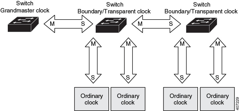
In the preceding illustration, M signifies master port, and S signifies nonmaster, or subordinate port.
PTP clock hierarchy
This figure illustrates PTP clocks in a time source-time recipient hierarchy within a PTP network
PTP VLAN and synchronization
The key aspects of PTP VLAN functionality and synchronization include:
-
All PHY PTP clocks synchronize to the GC.
-
The router system clock does not synchronize as part of PTP configuration and processes.
-
When VLAN is enabled on the GMC, it must be in the same VLAN as the native VLAN of the PTP port on the router.
-
GMC can drop untagged PTP messages when a VLAN is configured on the GMC.
-
To ensure the router sends tagged packets to the GMC, use the
vlan dot1q tag nativecommand in the global configuration mode.
Message-based PTP synchronization
Message-based PTP synchronization is a method that synchronizes clocks across network devices by exchanging messages, measuring path delays, and adjusting time information for accuracy. It
-
exchanges messages between the time source (Grandmaster Clock) and the time recipient to synchronize clocks.
-
measures the precise transmit and receive times of these messages to calculate the communication path delay, and
-
adjusts the current time information in network data based on the calculated delay to achieve highly accurate time synchronization.
Delay measurement in PTP synchronization
The delay measurement calculates the path delay between devices on the network and adjusts local clocks accordingly. It uses a series of messages exchanged between the time source and time recipient devices. The one-way delay is determined by averaging the path delay of the transmit and receive messages. This calculation assumes a symmetrical communication path, but switched networks may not have symmetrical paths due to the buffering process.
PTP uses transparent clocks to measure and account for the delay in the time-interval field of network timing packets. This approach makes switches temporarily transparent to the time source and time recipient nodes on the network. An end-to-end transparent clock forwards all messages across the network similar to a switch.
 Note |
Cisco PTP supports multicast PTP messages only. A PTP port may experience one or two timestamp retrieval failures when a 1G fiber SFP transceiver is removed and reinserted. Use the show ptp lan port interface Gig1/0/1 counters errors command to check PTP errors. To prevent this issue, ensure that all SFPs are installed before the system boots. Alternatively, you can insert the SFP during system boot and connect the fiber cable later when you need to bring up. |
For more details on synchronization messages, refer to PTP event message sequences .
For more details on calculation of network delays, refer to Transparent Clock.
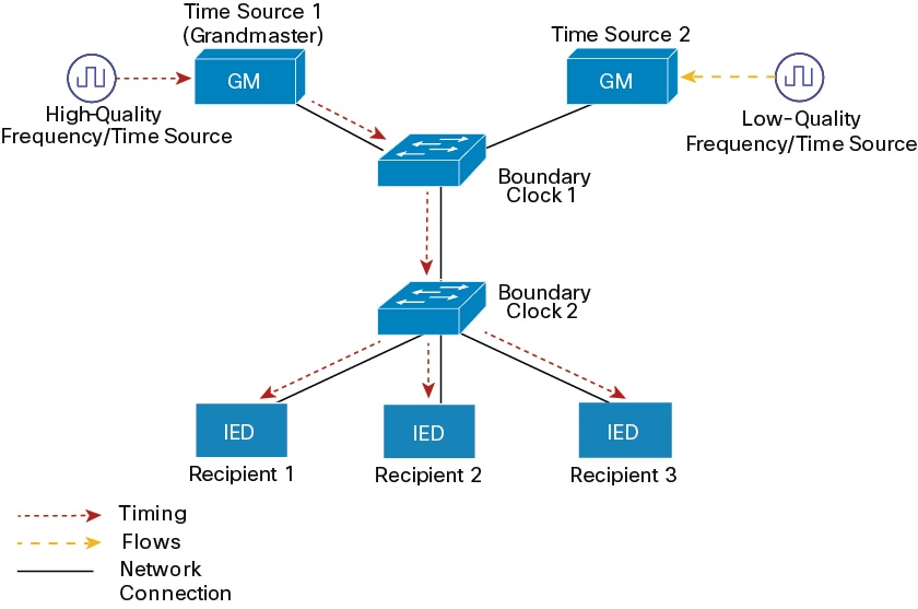
Distributing precise timings
The key components involved in the process are:
-
Time Source 1 (Grandmaster): The primary, high-quality source of time and frequency that initiates the timing distribution.
-
Time Source 2: A secondary, lower-quality source of time and frequency, potentially serving as a backup or alternative.
-
Boundary Clock 1: A network device (example: a switch) that synchronizes its internal clock with the Grandmaster and then acts as a time source for downstream devices.
-
Boundary Clock 2: A network device that synchronizes its internal clock with Boundary Clock 1 and distributes the precise timing to the end-point recipients.
-
IED (Intelligent Electronic Device) or recipient: End devices that receive and utilize the precise timing information for their operations.
Summary
PTP networks distribute precise timing information from a highly accurate source to various network devices, ensuring synchronization across the system.
-
Time Source 1 (Grandmaster): Initiates timing distribution.
-
Time Source 2: Backup or alternative time source.
-
Boundary Clock 1: Synchronizes with Grandmaster and distributes timing downstream.
-
Boundary Clock 2: Synchronizes with Boundary Clock 1 and distributes timing to recipients.
-
IED (Recipient): Receives and uses precise timing.
Synchronization is achieved through a series of stages, ensuring all devices operate with coordinated timing.
Workflow
These stages describe the distribution of timing information in a PTP network.
- Grandmaster Initialization: A high-quality frequency or time source provides highly accurate timing to Time Source 1, which functions as the Grandmaster.
- Grandmaster to Boundary Clock 1 distribution: The Grandmaster transmits its precise timing information to Boundary Clock 1 over a network connection.
- Boundary Clock 1 to Boundary Clock 2 synchronization: Boundary Clock 1 synchronizes its clock with the Grandmaster and then forwards the timing information to Boundary Clock 2.
- Boundary Clock 2 to recipient distribution: Boundary Clock 2 synchronizes its clock with Boundary Clock 1 and distributes the precise timing to the connected IEDs (Recipient 1, Recipient 2, and Recipient 3).
Result
All connected IEDs (Recipients) receive synchronized and precise timing information, enabling coordinated and time-sensitive operations across the network.
PTP event message sequences
This section explains the sequence of PTP event messages during synchronization.
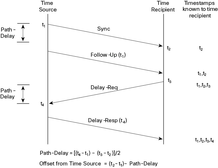
Boundary Clocks synchronization
The key components involved in the process are:
-
Time Source: The entity that provides the reference time.
-
Time Recipient: The entity that seeks to synchronize its clock with the Time Source.
-
Sync message: A message sent by the Time Source to initiate synchronization.
-
Follow-Up message: A message sent by the Time Source to provide the precise departure timestamp (t1) of the Sync message.
-
Delay-Req message: A message sent by the Time Recipient to the Time Source to request delay measurement.
-
Delay-Resp message: A message sent by the Time Source to the Time Recipient, containing the arrival timestamp (t4) of the Delay-Req message.
-
Path-Delay: The calculated one-way network latency between the Time Source and Time Recipient.
-
Offset from Time Source: The calculated time difference between the Time Recipient's clock and the Time Source's clock.
Summary
Network time synchronization ensures that different devices or systems maintain a consistent and accurate understanding of time, which is crucial for logging, data correlation, and distributed operations.
Workflow
The network time synchronization process involves these stages:
- Sync message transmission: The Time Source sends a Sync message to the Time Recipient and notes the time (t1) it sends the message.
- Sync message reception: The Time Recipient receives the Sync message and notes the time (t2) it receives the message.
- Follow-Up message transmission: The Time Source sends the timestamp t1 to the Time Recipient in a Follow-Up message.
- Delay request transmission: The Time Recipient sends a Delay-Req message to the Time Source and notes the time (t3) it sends the message.
- Delay request reception: The Time Source receives the Delay-Req message and notes the time of reception (t4).
- Delay response transmission: The Time Source sends the timestamp t4 to the Time Recipient in a Delay-Resp message.
-
Path-Delay calculation: The Time Recipient calculates the
Path-Delay
using the formula
[(t4 - t1) - (t3 - t2)] / 2. -
Offset calculation: The Time Recipient calculates the offset from the Time Source using the formula
(t2 - t1) - Path-Delay.
Result
This process enables the Time Recipient to obtain all four necessary timestamps (t1, t2, t3, t4) to calculate the network path delay and its clock's offset relative to the Time Source. This allows the Time Recipient to adjust its clock for precise synchronization. It is important to note that the calculation assumes symmetrical propagation time between the source and recipient; however, this assumption may not hold true on all networks, such as Ethernet, due to asymmetrical packet delay times.
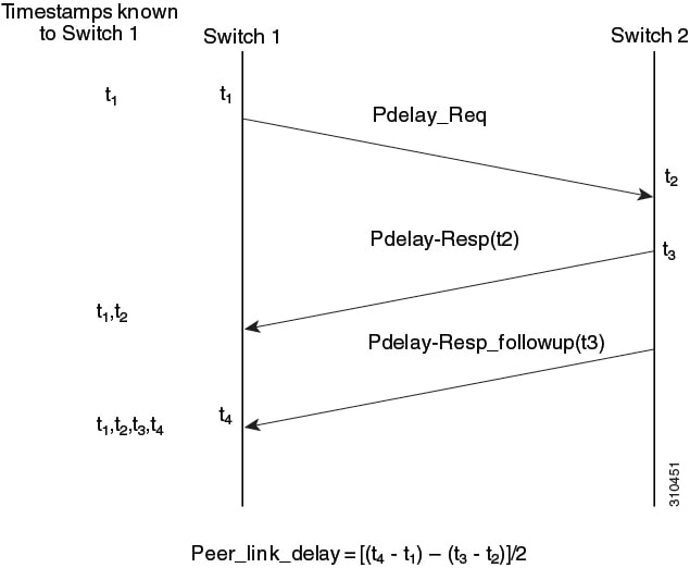
Peer-to-Peer Transparent Clock synchronization
Peer link delay measurement is a mechanism used to precisely determine the communication delay over a direct link between two network devices. This process is essential for accurate time synchronization protocols like PTP.
-
It enables devices to compensate for propagation delays and achieve highly precise time synchronization across the network.
Summary
The key components involved in the process are:
-
Switch 1: The initiating device that sends delay requests and calculates the peer link delay.
-
Switch 2: The responding device that receives delay requests, sends responses, and provides its internal timestamps.
-
Pdelay_Req: A message sent by Switch 1 to initiate the delay measurement process.
-
Pdelay-Resp: A message sent by Switch 2 in response to a Pdelay_Req , containing the timestamp of its reception (
t2). -
Pdelay-Resp_followup: A subsequent message sent by Switch 2 that provides the precise timestamp of when it transmitted the Pdelay-Resp message (
t3). -
Timestamps (t1, t2, t3, t4): Specific points in time recorded by the switches during the message exchange to measure transmission and reception times.
This process is essential for accurate time synchronization protocols like PTP.
Workflow
These stages describe the sequence of message exchanges and timestamp recordings for peer link delay measurement:
-
Request initiation: Switch 1 sends a
Pdelay_Req
message to Switch 2 and records the precise time of transmission as
t1.- Switch 1 generates timestamp t1 for a Pdelay_Req message.
-
Request reception: Switch 2 receives the
Pdelay_Req
message from Switch 1 and records the precise time of reception as
t2.- Switch 2 receives Pdelay_Req and generates timestamp t2 for this message.
-
Response transmission: Switch 2 prepares and sends a
Pdelay-Resp
message back to Switch 1. This message includes the
t2timestamp. Switch 2 also records the precise time of transmitting this Pdelay-Resp message ast3.- Switch 2 generates timestamp t3 for a Pdelay_Resp message.
- To minimize errors due to any frequency offset between the two switches, Switch 2 returns the Pdelay_Resp message as quickly as possible after the receipt of the Pdelay_Req message.
-
Follow-up transmission: Shortly after sending the
Pdelay-Resp
, Switch 2 sends a
Pdelay-Resp_followup
message to Switch 1. This
Follow-up
message contains the
t3timestamp, providing a precise record of the Pdelay-Resp 's transmission time.- Switch 2 returns timestamps t1, t2, and t3 in the Pdelay_Resp and Pdelay_Resp_Follow_Up messages respectively.
-
Response reception and calculation: Switch 1 receives both the
Pdelay-Resp
and
Pdelay-Resp_followup
messages. It records the precise time of receiving these messages as
t4. Switch 1 then calculates the peer link delay using the formula:Peer_link_delay = [(t4 - t1) - (t3 - t2)]/2.- Switch 1 generates timestamp t4 after receiving the Pdelay_Resp message. Switch 1 then uses the four timestamps (t1, t2, t3, and t4) to calculate the mean link delay between Switch 1 and Switch 2.
Result
The process accurately determines the one-way communication delay over a specific network link, allowing devices to compensate for propagation delays and achieve highly precise time synchronization across the network.
Synchronize the local clock
Synchronizing the local clock ensures that the device's clock aligns with the time source by correcting drift using PTP timestamp information and FollowUp messages.
Best Master Clock Algorithm
The Best Master Clock Algorithm (BMCA) is a process that continuously selects the best time source clock in a PTP network subdomain from all visible clocks, including itself. The BMCA identifies the best time source clock in the subdomain based on:
-
clock quality (example: GPS is considered the highest quality),
-
accuracy of the clock's time base,
-
stability of the local oscillator, and
-
proximity to the grandmaster clock.
BMCA operation
The BMCA operates continuously on the network and adapts quickly to changes in network configuration.
-
BMCA prevents clocks from negotiating with one another.
-
BMCA avoids misconfigurations, such as multiple or missing time source clocks, during the identification process.
PTP profiles
IEEE 1588 defines a PTP profile as a set of allowed PTP features for a device, tailored to a specific application or environment.
Cisco Catalyst IE9300 Rugged Series Switches supports these PTP profiles:
-
Default
-
Power
Cisco IOS-XE Release 17.7.1 supports Power Profile-2011, defined in the PC37.238-2011 IEEE Draft Standard Profile for using IEEE 1588 PTP in Power System Applications.
Note |
This documentation uses the terms Power Profile mode and Default Profile mode to refer to the IEEE 1588 profile and its configuration values. |
Starting from Cisco IOS-XE Release 17.8.1, Cisco Catalyst IE9300 Rugged Series Switches supports Power Profile-2017 in Transparent clock. Power Profile-2017 is defined in IEEE Standard C37.238™-2017 (a Revision of IEEE Std C37.238-2011) for use of IEEE 1588 PTP in Power System Applications.
PTP profiles specify these values:
-
BMCA options
-
Configuration management options
-
Path delay mechanisms (peer delay or delay request-response)
-
Range and default values of all PTP configurable attributes and data set members
-
Transport mechanisms that are required, permitted, or prohibited
-
Node types that are required, permitted, or prohibited
-
Options that are required, permitted, or prohibited
Default profile mode
The Default profile mode is the default PTP profile for Cisco Catalyst IE9300 Rugged Series Switches. It
-
supports Grand Master boundary clock, Boundary Clock (BC), Transparent Clock (TC), and PTP forward mode (PTP passthrough) on the default profile.
-
does not support Ordinary Clock (OC), and
-
does not support all PTP profiles over bundles or port-channels.
Power profile mode (2011 and 2017)
The IEEE Power Profile mode is a set of configuration values and operational guidelines that optimize PTP networks for use in power substations, ensuring consistent and reliable time distribution. It
-
specifies optimal physical layer and higher-level protocol for PTP messages.
-
ensures consistent time distribution within and between substations, and across wide geographic areas, and
-
defines preferred BMCA and configuration values.
Power profile mode and configuration
The switch is optimized for PTP in these ways:
-
Hardware —The switch uses FPGA and PHY for the PTP function. The PHY timestamps the Fast Ethernet and Gigabit Ethernet ports.
-
Software —In Power Profile mode, the switch uses the configuration values defined in the IEEE 1588 Power Profile standard.
This table displays the IEEE 1588 power profile configuration values and shows how the Cisco Catalyst IE9300 Rugged Series Switches apply them for each PTP profile mode.
|
PTP field |
Power profile modes (2011 and 2017) |
Default profile mode |
|---|---|---|
|
Message transmission |
Access Ports –Untagged Layer 2 packets. Trunk Ports –802.1Q tagged Layer 2 packets. PTP packets are tagged with the PTP VLAN. If the PTP VLAN is not configured, packets go untagged over the native VLAN. |
Layer 3 packets. By default, 802.1Q tagging is disabled. |
|
MAC address–Non-peer delay messages |
01-00-5e-00-01-81. |
Default profile uses L3 transport multicast address 224.0.1.129 for all PTP messages. Equivalent MAC address is 01-00-5e-00-01-81 |
|
MAC address-Peer delay messages |
01-80-C2-00-00-0E. |
Not applicable to this mode. |
|
Domain number |
0. |
0. |
|
Path delay calculation |
Peer-to-peer transparent clocks using the peer_delay mechanism. |
End-to-end transparent clocks using the delay_request mechanism. |
|
BMCA |
Enabled. |
Enabled. |
|
Clock type |
Two-step. |
Two-step. |
|
Time scale |
Epoch. |
Epoch. |
|
Grandmaster ID and local time determination |
|
PTP-specific type, length, and value to indicate Grandmaster ID. |
|
Time accuracy over network hops |
Over 16 hops, slave device synchronization accuracy is within 1 usec (1 microsecond). |
Not applicable in this mode. |
PTP profile comparison
This table provides the comparison of different PTP power profiles on IE switches.
|
Profile |
Default (*) |
Power profile-2011 |
Power profile-2017 |
|||
|---|---|---|---|---|---|---|
|
Standard |
IEEE1588 v2 (J.3) |
IEEE C37.238-2011 |
IEEE C37.238-2017 |
|||
|
Mode |
Boundary |
End-to-End transparent |
Boundary |
Peer-to-Peer transparent |
Peer-to-Peer transparent |
|
|
Path Delay |
Delay req/res |
Delay req/res |
Peer delay req/res |
Peer delay req/res |
Peer delay req/res |
|
|
Non-PTP device allowed in PTP domain |
Yes |
Yes |
No |
No |
No |
|
|
Transport |
UDP over IP (multicast) |
L2 Multicast |
L2 Multicast |
|||
Note |
* Delay Request-Response Default PTP profile (as defined in IEEE1588 J.3). |
PTP profile switch tag behavior
This table describes the switch tagging behavior in Power profile and Default profile mode.
|
Switch Port Mode |
Configuration |
Power Profile Modes (2011 and 2017) |
Power Profile Modes (2011 and 2017) |
Default Profile Mode |
Default Profile Mode |
|---|---|---|---|---|---|
|
Behavior |
Priority |
Behavior |
Priority |
||
|
Trunk Port |
vlan dot1q tag native enabled |
Switch tags packets |
7 |
Switch tags packets |
7 |
|
Trunk Port |
vlan dot1q tag native disabled |
PTP software tags packets |
4 |
Untagged |
None |
|
Access Port |
N/A |
Untagged |
None |
Untagged |
None |
Boundary Clock Synchronization algorithm
The Boundary Clock Synchronization algorithm (BCSA) is a method for configuring PTP clocks to prioritize either filtering packet delay variation (PDV) or achieving faster convergence.
BCSA details
You can configure the BCSA based on your PTP use case, prioritizing either filtering input time errors or achieving faster convergence. A PTP algorithm that filters packet delay variation (PDV) converges more slowly than one without filtering.
-
By default, the BC uses a linear feedback controller (servo) to adjust its time output to the next clock. The linear servo offers minimal PDV filtering and achieves average convergence time.
-
For faster convergence, the BC can use the TC feedforward algorithm, which measures the delay introduced by the network elements' forwarding plane (the disturbance) and uses this delay to control the time output.
-
The feedforward BC significantly improves BC performance but does not filter PDV.
-
The adaptive PDV filter ensures high-quality time synchronization even when wireless access points (APs) and enterprise switches, which do not support PTP, introduce significant PDV.
BC synchronization supports three options which are compliant with IEEE 1588-2008:
-
Feedforward—For very fast and accurate convergence but does not filter PDV.
-
Adaptive—Adaptive filters maximize PDV filtering based on assumptions about PDV characteristics, hardware configuration, and environmental conditions.
Note
With the adaptive filter, the switch does not meet the time performance requirements specified in ITU-T G.8261.
-
Linear—Provides simple linear filtering which is the default.
Adaptive mode ptp transfer filter adaptive is not available in Power Profile mode.
NTP to PTP time conversion
NTP to PTP time conversion is a feature that allows you to use NTP as a time source for PTP, enabling precise synchronization within a site and broader synchronization across sites where high precision is not required.
Example of NTP to PTP time conversion
NTP is the traditional method to synchronize clocks in packet-based networks, using a two-way time transfer mechanism between a time source and an end device. NTP synchronizes a device within a few hundred milliseconds over the internet and within a few milliseconds in a controlled LAN. Using NTP as a PTP time source lets you correlate data from your PTP network with data in enterprise data centers running NTP.
NTP to PTP conversion
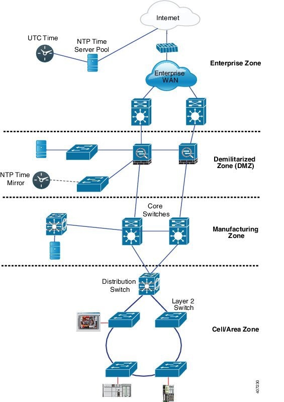
Time synchronization in industrial networks relies on a layered approach, beginning with a global UTC source and progressing through various network zones to reach end devices. This ensures accurate and reliable time for both IT and OT systems.
This process enables precise time synchronization across all network zones, culminating in NTP to PTP conversion for industrial automation equipment.
Summary
The key actors and components involved in this process are:
Time sources and network zones
-
UTC Time: Provides the global reference for accurate time synchronization.
-
NTP Time Server Pool: Acquires time from UTC sources and distributes it via NTP.
-
Internet: Connects the NTP Time Server Pool to the Enterprise WAN.
-
Enterprise WAN: Connects enterprise infrastructure to the internet.
-
Enterprise zone: Main network segment for enterprise operations.
-
Demilitarized zone (DMZ): Secure buffer hosting the NTP Time Mirror.
-
Manufacturing zone: Dedicated to manufacturing operations requiring accurate time.
Network infrastructure and end device
-
NTP time mirror: Local NTP server in the DMZ synchronizing with external NTP sources.
-
Core switches: Backbone of the network, connecting zones and distributing traffic.
-
Distribution switch: Aggregates connections and distributes to lower-level segments.
-
Layer 2 switch: Provides connectivity to end devices within local segments.
-
Industrial Devices: PLCs and HMIs in the Cell/Area Zone requiring precise time via PTP.
Workflow
The process involves these stages:
-
Global time source acquisition: The NTP Time Server Pool obtains highly accurate time from a UTC time source over the internet,
ensuring a precise global time reference.
- UTC time is acquired by NTP Time Server Pool.
- Internet provides connectivity for time acquisition.
-
Enterprise network distribution: The NTP Time Server Pool distributes synchronized NTP time to the Enterprise Zone, including
the Enterprise WAN and core network infrastructure.
- Enterprise WAN receives NTP time from the server pool.
- Core switches distribute NTP time within the enterprise zone.
-
DMZ time mirroring: An NTP Time Mirror in the DMZ synchronizes with the external NTP Time Server Pool, providing a secure
and reliable local NTP time source.
- NTP Time Mirror synchronizes with external NTP sources.
- DMZ acts as a secure buffer for time distribution.
-
Manufacturing zone synchronization: Core switches and devices in the Manufacturing Zone obtain time from the NTP Time Mirror
in the DMZ.
- Core switches distribute NTP time to manufacturing devices.
- Manufacturing zone relies on synchronized time for process control.
-
Industrial network connectivity: The Distribution Switch connects the Manufacturing Zone's core network to the Cell/Area Zone,
which contains critical industrial control systems and devices. Layer 2 switches further distribute network connectivity within
this zone to the industrial equipment.
- Distribution Switch links manufacturing core to Cell/Area Zone.
- Layer 2 switches connect end devices within the Cell/Area Zone.
-
PTP conversion enablement: Within the cell or area zone, distributed NTP time serves as a reference for devices that convert
NTP to PTP, providing extremely precise time synchronization for industrial automation equipment.
- Specialized devices convert NTP to PTP.
- PLCs and HMIs use PTP for coordinated operations.
Result
This hierarchical time synchronization process ensures that all network zones, from enterprise IT to critical industrial operational technology (OT), receive accurate and consistent time. This enables precise timestamping, synchronized operations, and the high-fidelity timing required for sensitive industrial control applications through the enablement of NTP to PTP conversion at the network edge.
Clock manager
The clock manager is a software component that tracks various time services, selects the active clock providing time, and notifies time services of key changes such as state changes, leap seconds, or daylight saving time. It
-
prioritizes NTP or manually set clock first, then PTP, and finally the real-time clock if NTP is inactive.
-
ensures the time displayed in show ptp clock and show clock commands match under normal conditions.
Clock manager selection
The clock manager determines which time source is active and ensures synchronization between Cisco IOS and PTP clocks, with specific behaviors in certain configurations.
The following table shows the results of the clock selection process based on the status of NTP, PTP, and the real-time clock:
|
NTP (Active) or Manually Set |
PTP (Active) |
Real-Time Clock |
Selected Output |
|---|---|---|---|
|
True |
Don’t care |
Don’t care |
NTP or Manually Set |
|
False |
True |
Don’t care |
PTP |
|
False |
False |
True |
Real-Time Clock |
There are two corner cases where the show ptp clock time may differ from the show clock command output:
-
The switch acts as a TC or BC with no other active reference on the network. In this case, the TC and BC take their time only from the network’s PTP GMC, not from the clock manager. If no active PTP GMC exists, the show clock and show ptp clock command outputs may differ.
-
The switch is a syntonizing TC, a BC with a subordinate port, or a GMC-default with a subordinate port, and the time from the PTP GMC does not match the time from NTP or the user (manually set). In this case, the PTP clock must forward the time from the PTP GMC. If the PTP clock does not follow the PTP GMC, the PTP network has two different time bases, disrupting control loops or sequence-of-event applications that rely on PTP.
This table shows how the Cisco IOS and PTP clocks behave given various configurations. Most of the time, the two clocks match. Occasionally, the two clocks are different; those configurations are highlighted in the table.
|
IOS Clock Configuration |
PTP Clock Configuration |
IOS Clock Source |
PTP Clock Source |
|---|---|---|---|
|
Calendar |
PTP BC, E2E TC, or GMC-BC in BC Mode |
PTP |
PTP |
|
Manual |
PTP BC, E2E TC, or GMC-BC in BC Mode |
Manual |
PTP |
|
NTP |
PTP BC, E2E TC, or GMC-BC in BC Mode |
NTP |
PTP |
|
Calendar |
GMC-BC in GM Mode |
Calendar |
Calendar |
|
Manual |
GMC-BC in GM Mode |
Manual |
Manual |
|
NTP |
GMC-BC in GM Mode |
NTP |
NTP |
Grandmaster clock
The Grandmaster clock (GMC) is a network security feature that prevents rogue GMC devices from synchronizing with devices inside the network. GMC
-
allows only egress Announce , Sync , and Follow_Up PTP packets while dropping all ingress packets of these types on the interface. This prevents the port state from transitioning to a time recipient.
-
supports all PTP clock modes except forward mode, and
-
detects rogue GMC devices and generates Syslog messages, relay minor alarms, and SNMP traps for notification.
Grandmaster clock block operation and notifications
The GMC block feature operates by filtering PTP packets and providing mechanisms to identify and notify about rogue devices.
-
Information about rogue GMCs is retrieved from their packets before being dropped.
-
Details such as IP address and clock ID of rogue devices are stored and displayed for the interface.
-
Two Syslog messages are generated to notify both the detection and clearance of rogue devices.
-
Per-port Syslog messages are displayed 30 seconds after receiving rogue packets and 180–240 seconds after the packets stop.
-
Relay minor alarms and SNMP traps are generated to notify about the presence of foreign rogue devices.
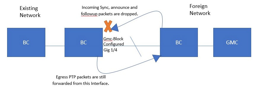
Packet flow with GMC block
The PTP network topology with GMC block figure shows an example of a PTP network topology with the GMC Block feature configured on an interface.
Summary
The key components are the Grandmaster Clock (GMC) of the foreign network, the local GMC, and the port configured with GMC Block.
-
The GMC of the foreign network attempts to sync with the existing network by sending PTP packets.
-
The port configured with GMC Block drops incoming PTP packets from the foreign network after retrieving required information.
-
The local GMC in the existing system maintains synchronization.
-
PTP packets originated on the port with GMC Block are allowed to egress, enabling devices in the existing network to be GMC.
This process ensures that only the local GMC is used for synchronization, restricting packets from the foreign network while allowing local devices to act as GMC.
Workflow
These stages describe the packet flow and synchronization behavior when GMC Block is configured on an interface.
-
Stage 1: PTP packets originate in the GMC of the foreign network and attempt to sync with the existing network.
- Foreign GMC sends PTP packets to the network.
- Packets reach the port configured with GMC Block.
-
Stage 2: PTP packets originated on the port configured with GMC Block are allowed to egress from this interface.
- Local devices send PTP packets from the port with GMC Block.
- Packets egress from the interface, allowing devices in the existing network to be GMC.
PTP restrictions
Follow these guidelines to avoid unsupported configurations and ensure reliable PTP operation.
General PTP guidelines
-
The Cisco PTP implementation supports only two-step clock operation in BC mode. One-step clock is not supported.
-
Cisco PTP supports multicast PTP messages only.
-
Cisco PTP supports only PTP version2.
-
Power Profile-2017 supports only transparent clock mode.
PTP mode and profile
-
The switch and the grandmaster clock must be in the same PTP domain.
-
When Power Profile mode is enabled, the switch drops PTP announce messages that do not include the Organization_extension and Alternate_timescale TLV message extensions.
If the GMC is not compliant with PTP and sends announce messages without these TLVs, configure the switch to process the announce message by entering this command:
ptp clock boundary domain 1 profile {power | power-2017}allow-without-tlv -
When the switch is in Power Profile mode, only the peer_delay mechanism is supported.
To enable Power Profile boundary mode and associate interfaces using the clock-port suboption, enter these commands:
ptp clock boundary domain 1 profile {power | power-2017} clock-port 1 transport ethernet multicast interface gi0/1/1 -
To disable power profile transparent mode, enter this command, which returns the switch to forward mode.
no ptp clock transparent domain x profile {power | power-2017} -
To enable the E2E transparent clock, use this command:
ptp clock transparent domain x profile default - In Default Profile mode, only the delay_request mechanism is supported.
To enable Default Profile BC mode and interfaces associated with clock-port suboption, enter this command:
ptp clock boundary domain 1 profile default
clock-port 1
transport ipv4 multicast interface gi0/1/1
Packet format
-
PTP messages can use 802.1Q tagged packets or untagged packets.
-
The switch does not support 802.1Q QinQ tunneling.
-
In Power Profile mode:
-
When the PTP interface is configured as an access port, PTP messages are sent as untagged Layer 2 packets.
-
When the PTP interface is configured as a trunk port, PTP packets are sent as 802.1Q tagged Layer 2 packets over the port's native VLAN.
-
-
Time recipient IEDs must support tagged and untagged packets.
-
In E2E TC mode, PTP packets sent on the native VLAN are untagged. To send them as tagged packets, use the
vlan dot1q tag nativecommand in global configuration mode.
NTP to PTP conversion
The NTP to PTP feature supports the default E2E profile and Power profile.
PTP interaction with other features
This topic describes the supported and unsupported PTP interactions with other features on the Cisco IE9300 Series Switches.
-
PTP is supported over PRP starting with Cisco IOS XE Cupertino 17.9.1. For more information, refer to the Redundancy Protocol Configuration Guide, Cisco Catalyst IE9300 Rugged Series Switches .
-
Cisco IE9300 Rugged Series Switches do not support PTP over Port Channels. Because PTP is enabled by default, configuring Port-Channels while PTP is active may lead to unpredictable behavior or network instability. To ensure stable operation:
-
Disable PTP before configuring Port-Channels.
-
If PTP functionality is required elsewhere on the switch, disable it specifically on the interfaces participating in the Port-Channel.
-
If PTP is not required in your deployment, remove all PTP-related configurations from the switch.
-
-
PTP is not supported over stacking.
-
PTP is not supported over Cisco Resilient Ethernet Protocol (REP).
-
The e2etransparent and p2ptransparent PTP clock modes only operate on a single VLAN.
Default settings
By default, the switch is configured with these PTP settings.
-
PTP is enabled.
-
Default profile mode is enabled, using configuration values defined in the Default profile.
-
The PTP clock mode is set to End-to-End (E2E) Transparent Clock mode.
-
The Boundary Clock (BC) synchronization algorithm is set to the linear filter.
 Feedback