IRIG-B

IRIG time code B

Inter-Range Instrumentation Group (IRIG) time code B (IRIG-B) is a standard format for transferring timing information to devices, especially in environments where Precision Time Protocol (PTP) or Network Time Protocol (NTP) are not supported on Ethernet interfaces. IRIG-B:

  • enables timing information transfer to devices lacking PTP or NTP support, and

  • widely used in power, industrial automation, and control industries for time distribution and synchronization.

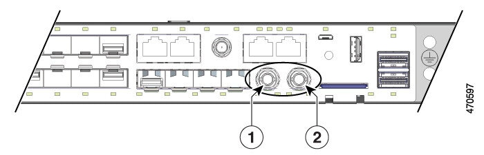
IE9320 GE Fiber ( IE-9320-22S2C4X-E and IE-9320-22S2C4X-A) switches have integrated IRIG-B interfaces to provide an external timing source. The switches support IRIG-B from IOS XE Release 17.12.1.

Key facts of IRIG-B

IRIG time codes were developed to standardize timing codes for U.S. military test ranges in the late 1950s, resulting in a set of codes that enabled synchronized data exchange across ranges. Six IRIG codes (A, B, D, E, G, H) variations are developed. IRIG-B became the most widely accepted for time distribution in industrial sectors.

  • The IRIG standard was first published in 1960, with the latest version (IRIG standard 200-04) updated in September 2004 as IRIG Serial Time Code Formats .

  • IRIG sends a complete time frame once per second, with each frame composed of 100 bits.

  • IRIG contains time-of-year and year information in binary coded decimal (BCD) format, and optionally seconds-of-day in straight-binary seconds (SBS) format.

  • IRIG is a reliable and predictable timing source distribution framework but relies on a precise timing source, such as GPS.

  • The IRIG-B time protocol is widely used by electric utilities and other verticals to maintain time synchronization between system devices, such as power breakers, relays, and meters.

IRIG-B timecode input and output capabilities

IE9320 GE Fiber ( IE-9320-22S2C4X-E and IE-9320-22S2C4X-A) switches have IRIG-B timecode input and output capability. It has:

  • Mini-BNC connectors are used for both digital and analog IRIG-B timecode.

  • Each connector can be set as input or output independently.

  • LEDs indicate configuration and signal status for each channel.

IRIG-B connectors and LED status

The following table describes the IRIG-B connector locations on the switch front panel:

Table 1. IRIG-B connector locations

1

IRIG-B digital timecode connector (mini-BNC connector)

2

IRIG-B analog timecode connector (mini-BNC connector)

This table shows the behavior of IRIG timecode LEDs located below the connectors:

Table 2. IRIG timecode LED behavior

LED

Color

System Status

Analog In

Off

Analog timecode input is not configured.

Analog In

Solid Green

Analog timecode input is present and operating properly.

Analog In

Alternating Green and Amber

Analog timecode signal is present with errors.

Analog In

Blinking Amber

Analog timecode input configured, no signal present.

Analog Out

Off

Analog timecode output is not configured.

Analog Out

Solid Green

Analog timecode output is configured and sending a signal.

Digital In

Off

Digital timecode input is not configured.

Digital In

Solid Green

Digital timecode input is present and operating properly.

Digital In

Alternating Green and Amber

Digital timecode signal is present with errors.

Digital In

Blinking Amber

Digital timecode input configured, no signal present.

Digital Out

Off

Digital timecode output is not configured.

Digital Out

Solid Green

Digital timecode output is configured and sending a signal.


Note


You must buy or build cables for IRIG-B connectivity as per the IRIG-B standard and switch's specifics. These cables are not provided with the platform.


This illustration shows the two IRIG-B connectors on the switch's front side.

Figure 1. IRIG timecode connectors


Cisco IOS XE version for IRIG-B input and output

Cisco IOS XE supports IRIG-B INPUT and OUTPUT capabilities.

Refer the Release Notes for Cisco Catalyst IE9300 Rugged Series Switches and Cisco’s recommendations before upgrading IOS XE versions on your switch.

This table shows the minimum required Cisco IOS XE versions to support IRIG-B signaling direction.

Table 3. Cisco IOS XE for IRIG-B directions

IRIG-B direction

Minimum IOS XE support

Output

Cisco IOS XE.17.12.1

Input

IRIG-B direction and time sources

Cisco IE9320 GE Fiber switches provide two physical interfaces for IRIG-B: one analog (AM) and one digital (TTL), each supporting input or output signal capabilities. These interfaces enable the switch to function as a central timing device in a network.

IRIG-B input and output signaling

IRIG-B input or output signaling allows the Cisco IE9320 GE Fiber switch to serve as a central timing device in multiple scenarios.

  • Input: The switch receives IRIG-B timing signaling (AM or TTL) from an IRIG-B time source only if available or required. In this case, IRIG-B can be used as the switch clock source for PTP only. The switch is configured as the Grand Master Clock (GMC) for time distribution.

  • Output: The switch utilizes other precise timing sources—such as GNSS (GPS), PTP, or NTP—as a clock source. The IRIG-B interfaces can be used to transmit timing signals to IRIG-B dependent devices in the location.

This table shows the mapping of the time source to the time distribution protocol:

Table 4. Mapping of time source and time distribution

Time Source

Time Distribution

PTP

IRIG-B in

GNSS (GPS), PTP, NTP

IRIG-B out

Example: IRIG-B input and output configuration

For example, when the switch receives IRIG-B input from a GPS-based time source, it can act as a Grand Master Clock for PTP distribution. When switch uses GNSS, PTP, or NTP as the clock source, it can output IRIG-B signals to synchronize dependent devices.

IRIG-B in Cisco IOS XE IE 9300 Rugged Series Switches

The IRIG-B protocol in Cisco IOS XE IE 9300 Rugged Series Switches is implemented according to the IRIG standard 200-04, supporting both analog (AM) and digital (TTL) time code formats for input and output. It:

  • supports 4x Analog (AM) and 4x Digital (TTL) IRIG-B time code formats

  • complies with IRIG standard 200-04 for time code transmission and reception, and

  • provides both input (receive) and output (transmit) capabilities for IRIG-B signals.

IRIG-B modes and format

This table lists the supported IRIG-B modes, format IDs, signal types, and descriptions for the IE9320 series switches.

Table 5. IE9320 IRIG-B modes and formats

IE9320 IRIG-B Modes

Format ID

IRIG Signal

Description

Analog (AM)

AM02

AM-B122

Amplitude Modulated, 1kHz / 1ms resolution, BCD TOY

AM03

AM-B123

Amplitude Modulated, 1kHz / 1ms resolution, BCD TOY , SBS

AM06

AM-B126

Amplitude Modulated, 1kHz / 1ms resolution, BCD TOY , BCD YEAR

AM07

AM-B127

Amplitude Modulated, 1kHz / 1ms resolution, BCD TOY , BCD YEAR , SBS

Digital (TTL)

TTL02

TTL-B002

Unmodulated, DCLS, pulse-width-coded, BCD TOY

TTL03

TTL-B003

Unmodulated, DCLS, pulse-width-coded, BCD TOY , SBS

TTL06

TTL-B006

Unmodulated, DCLS, pulse-width-coded, BCD TOY , BCD YEAR

TTL07

TTL-B007

Unmodulated, DCLS, pulse-width-code, BCD TOY , BCD YEAR , SBS

Configuration scenario

This configuration scenario shows two Cisco IE9320 GE Fiber switches ( IE-9320-22S2C4X-A and IE-9320-22S2C4X-E ) switches configured to use IRIG-B signaling in these different ways.

  • Time source GNSS (GPS), IRIG-B TTL07 OUT for time distribution—IE93200 (v23-ie9320-2)

  • Time source IRIG-B TTL07 IN, PTP for time distribution—IE93200 (switch)


Note


For configurations, refer Global Navigation Satellite System and Precision Time Protocol sections of this guide.


Configure IRIG-B

You can configure IRIG-B which sets the IRIG-B mode and signal direction for each interface. You can have two IRIG-B configurations.

Procedure


Step 1

Use the enable command to enable the privileged EXEC mode.

Example:

Switch> enable

Enter your password if prompted.

Step 2

Use the configure terminal command to enter global configuration mode.

Example:

Switch# configure terminal

Step 3

Use the irig mode command to configure IRIG.

irig mode mode_type

Example:

Switch(config)# irig mode AM02 AM-B122 format

The possible irig modes are AM02 AM-B122 format, AM03 AM-B123 format, AM06 AM-B126 format, AM07 AM-B127 format, TTL02 TTL-B002 format, TTL03 TTL-B003 format, TTL06 TTL-B006 format, TTL07 TTL-B007 format

Step 4

Use the irig mode TTL07 dir direction command to set the direction.

Example:

Switch(config)#irig mode TTL07 dir in

in : input direction.

out : output direction.


Configure a GNSS time source and IRIG-B out

The IE9320 GE Fiber switch is configured to use its GNSS (GP)S interface and, consequently, GPS as its time source. That is, IRIG-B sources its time from GPS. The IRIG-B digital interface is configured to provide timing signal Out to the other IE9320 GE Fiber switch (v23-ie9320-4).

Procedure


Step 1

Use the enable command to enable the privileged EXEC mode.

Example:

Switch> enable

Enter your password if prompted.

Step 2

Use the configure terminal command to enter global configuration mode.

Example:

Switch# configure terminal

Step 3

Use the gnss command to enable GNSS.

Example:

Switch(config)# gnss 

Step 4

Use the irig mode TTL07 dir out command to configure the IRIG mode and direction.

Example:

Switch(config)# irig mode TTL07 dir out

Step 5

(Optional) Use the show irig command to monitor the IRIG-B output and IRIG-B time source. Verify the IRIG-B output and that GNSS is the IRIG-B time source, as shown in the following example.

Example:

Switch# show irig
IRIG-B Digital mode TTL07 dir out <<<--- Confirms IRIG-B mode and direction as configured (OUT)
IRIG-B Analog mode disabled
IRIG-B Clk Id 3 Source GNSS time: Year: 2021 Day: 98 Hour 15 Min 7 Sec 20 <<-- GNSS Clock source
ns 1617894440419015968 (0x1673EA6BED413D20)
IRIG-B Virtual Clock State: INACTIVE <<<--- IRIG-B clock inactive, not an internal time source
*** IRIG-B input is disabled ***

Configure PTP time source and IRIG-B In

The IE9320 GE Fiber switch (Switch) is configured to receive IRIG-B TTL07 (In) timing signal from the other IE9320 GE Fiber switch (v23-ie93200-2) and use it as its time source. This is used as the timing source for PTP for time network distribution. No other timing sources or protocols are configured.

Before you begin

Procedure


Step 1

Use the enable command to enable the privileged EXEC mode.

Example:

Switch> enable

Enter your password if prompted.

Step 2

Use the configure terminal command to enter global configuration mode.

Example:

Switch# configure terminal

Step 3

Use the ptp clock boundary domain 0 profile default command to configure the switch for PTP as the Grand Master Clock boundary clock (GMC-BC).

Example:

Switch(config)# ptp clock boundary domain 0 profile default

Step 4

Use the gmc-default command to configure GMC as default clock.

Example:

Switch(config-ptp-clk)# gmc-default

Step 5

Use the irig mode TTL07 dir in command to configure the IRIG mode and direction.

Example:

Switch(config)# irig mode TTL07 dir in

Step 6

(Optional) Use the show irig command to monitor IRIG-B time source and PTP source time

Example:

Switch# show irig
IRIG-B Digital mode TTL07 dir in <<<--- Confirms IRIG-B mode and direction as configured (IN)
IRIG-B Analog mode disabled
IRIG-B Clk Id 2 Source IRIG-B time: Year: 2021 Day: 98 Hour 15 Min 7 Sec 20 <<-- IRIG-B source
ns 1617894440918157031 (0x1673EA6C0B0186E7)
IRIG-B Virtual Clock State: ACTIVE <<<--- IRIG-B clock active, time source possible for PTP
*** IRIG-B TTL input mode ***
B007 : Year 21 Day 98 Hour 15 Min 7 Sec 19 SBS 0xD4A7(54439) <<-- TTL-B007 signal received
NOTE: Input time shown is the last received frame time

Step 7

(Optional) Use the show ptp time-property command to view the PTP time source.

Example:

Switch# show ptp time-property
PTP CLOCK TIME PROPERTY
Current UTC offset valid: FALSE
Current UTC offset: 0
Leap 59: FALSE
Leap 61: FALSE
Time Traceable: FALSE
Frequency Traceable: FALSE
PTP Timescale: FALSE
Time Source: Other <<--- This denotes IRIG-B 

Note


Time Source: Other identifies IRIG-B because there is no IRIG classification in PTP messaging. If NTP is configured as the source, it shows Time Source: NTP.


Feature History for IRIG-B

The following table provides release and related information for the features that are documented in this guide. The features are available in all the releases after the one they were introduced in, unless noted otherwise.

Release

Feature

Feature Information

Cisco IOS XE Dublin 17.12.x

Inter-Range Instrumentation Group time code B (IRIG-B)

Cisco IE9320 GE Fiber switches have integrated IRIG-B interfaces to provide an external timing source. These interfaces help make the switches a robust industrial platform with strong precision timing capabilities.