Global Navigation Satellite System

The Global Navigation Satellite System (GNSS) is a positioning, navigation, and timing (PNT) service. It facilitates:

  • network synchronization planning,

  • enhances flexibility, and

  • strengthens resilience in managing synchronization challenges within hierarchical networks.

Global Navigation Satellite Systems for network synchronization

Time synchronization with GNSS in industrial networks

Industrial automation and control systems, utility networks, and military networks require a large number of devices to maintain an accurate and synchronized sense of time.

The Cisco Catalyst IE9300 Rugged Series Switches have a built-in GNSS receiver that enables the router to:

  • determine its own location

  • obtain an accurate time from a satellite constellation.

GNSS capability streamlines network synchronization by providing flexible and resilient time sourcing in hierarchical networks. Once the switch receives accurate time, it can act as the Grand Master Clock, distributing precise timing throughout the network.


Note


Only IE9320 GE Fiber (IE-9320-22S2C4X-E and IE-9320-22S2C4X-A) switches have GNSS receiver.


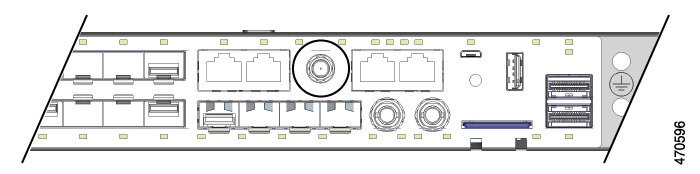
The GNSS receiver is on the front of IE9320 GE Fiber switches, and it has LEDs that enable you to monitor the feature's status. For more information, see the section "GNSS Antenna" in the Cisco Catalyst IE9300 Rugged Series Switch Hardware Installation Guide.

GNSS Hardware

Each IE9320 GE Fiber switch has receiver modules designed to provide a precise time pulse for the synchronization of 4G and 5G base stations. Each system has an SMA connector to attach an external GNSS antenna. It can provide current-limited power to power an active (amplified) antenna. For more information, see GNSS signaling in this guide.

The following illustration shows the placement of the connector on the front panel of IE9320 GE Fiber switches. The receiver is circled in the illustration.

Figure 1. SMA connector for GNSS Antenna


The GNSS receiver supports multiple satellite constellations as shown in the following table.

Band

Frequency

Constellations

L1

1602MHz

1575.42 MHz

Auto, GPS, GLONASS, QZSS, Galileo

1561.098 MHz

BeiDou

LEDs above the connector enable you to monitor GNSS status.

LED

Color

System Status

GPS

Off

GNSS is not configured.

Solid Green

Active with satellite fix.

Blinking Green

Attempting to acquire satellite fix.

Blinking Amber

Antenna Fault.

GNSS Software

The GNSS feature is available with the base license for IE9320 GE Fiber (IE-9320-22S2C4X-E and IE-9320-22S2C4X-A) switches. GNSS software performs the following functions:

  • Configures the GNSS receiver.

  • After the receiver has gained lock, performs the following functions once per second:

    • Reads the new time and date.

    • Reads the corresponding PPS timestamp from the hardware.

    • Feeds time/date and PPS timestamp into the Time Services SW Virtual Clock/Servo for GNSS.

      The GNSS SW Virtual Clock time can then be used to drive PTP output.

GNSS signaling

The GNSS receiver acquires satellites and provides timing signals to the host system in two ways.

  • Self-survey mode

  • Overdetermined clock mode

Summary

GNSS signaling calculates and stores position data to establish a stable reference and then delivers precise timing signals for reliable network synchronization. This is achieved through the Self-Survey and Overdetermined clock modes.

Workflow

Table 1. GNSS receiver modes

Mode

Description

Self-survey

This mode automates position calculation, result storage, and faster transitions to operational modes:

  • After a reset, the GNSS receiver enters self-survey mode.

  • It calculates a 3D position after locking onto at least four satellites.

  • Around 2,000 positions are calculated over 35 minutes.

  • Once complete, it generates timing signals and switches to the Normal (Locked to GPS) mode.

  • The Self-survey mode results are saved to the receiver’s flash memory, enabling quicker transitions to Overdetermined clock mode.

  • Each new self-survey overwrites the previous results in flash memory.

  • You can manually restart the self-survey using the gnss self-survey restart command.

Overdetermined clock

The device enters Overdetermined clock mode after completing the self-survey and storing position data in non-volatile memory. In this mode, the GNSS receiver provides timing information based on the satellite positions stored during the self-survey

Cisco IOS collects PPS signals only in Overdetermined clock mode, as timing signals during self-survey mode can have an error of up to 20 seconds.

The GNSS receiver stays in Overdetermined clock mode and can restart the self-survey in these scenarios:

  • automatically, if the antenna is moved more than 100m, and

  • manually, using the gnss self-survey restart command.

After locking onto a satellite system, the GNSS receiver sends a 10-ms-wide PPS (Pulse Per Second) pulse and the current time and date to the Cisco IOS time service.

GNSS Antenna Requirements

GNSS RF Input

GNSS input requires a GPS/GNSS receive antenna with built-in low-noise amplifier (LNA) for optimal performance. The LNA amplifies the received satellite signals:

  • To ccompensate for cable loss

  • To increase the signal amplitude to a suitable range for the receiver front-end

    The amplification required is 22dB gain + cable loss + connector loss.

    The recommended range of LNA gain (LNA gain minus all cable and connector losses) at the connector of the receiver input is 22dB to 30dB with a minimum of 20dB and a maximum of 35dB.

  • The GPS/GNSS input on the switch provides 3.3 or 5VDC (software configurable) to the antenna through the same RF connector. The antenna should draw between 10 and 100mA. An antenna that draws less than 10mA may wrongly report and "Antenna Open" fault even though the antenna is operating properly.

Power Input

When deployed in a hazardous environment the antenna shall only use power provided by the RF input from a single switch. No additional power may be supplied to the antenna and associated equipment.


Caution


Supplying additional power, such as with a powered splitter or amplified repeater, may provide enough energy to create an arc that could ignite the explosive atmosphere.

Attention :

L’ajout d’un dispositif d’alimentation électrique, comme un répartiteur électrique ou un répéteur amplifié, peut générer suffisamment d’énergie pour créer un arc qui pourrait enflammer une atmosphère présentant un risque d’explosion.


Surge Protection

The GNSS input has built-in ESD protection. If an outdoor antenna is being connected, additional surge protectionis required to meet the regulations and standards for lightning protection in the countries where the end product is installed.

The lightning protection must be mounted at the place where the antenna cable enters the building. The primary lightning protection must be certified for conducting all potentially dangerous electrical energy to PE (protective earth). Surge arrestors should support DC-pass and be suitable for the GPS/GNSS frequency range with low RF attenuation.


Caution


The antenna terminal should be earthed at the building entrance in accordance with the ANSI/NFPA 70, the National Electrical Code (NEC), in particular Section 820.93, Grounding of Outer Conductive Shield of a Coaxial Cable.

Attention :

La borne de l’antenne doit être mise à la terre à l’entrée du bâtiment conformément à la norme ANSI/NFPA 70 et au National Electrical Code (NEC), en particulier l’article 820.93, « Grounding of Outer Conductive Shield of a Coaxial Cable » (mise à la terre du blindage externe conducteur d’un câble coaxial).


Antenna Sky Visibility

GPS signals require a direct line of sight between antenna and satellite. The antenna should see as much of the sky as possible. Fixed installations require four satellites in view for an initial time fix, while subsequent updates may be possible with fewer satellites.

Restrictions for GNSS timing source

Use these guidelines when employing GNSS as a timing source and monitoring related events for GNSS on IE9320 GE Fiber (IE-9320-22S2C4X-E and IE-9320-22S2C4X-A) switches.

  • GNSS is available as a timing source only for the default PTP and power profiles.

  • GNSS can be used as a PTP timing source only when PTP is in GMC-BC default mode.

  • The supported syslog messages for GNSS events are:

    • entering self-survey mode,

    • reaching the OD mode, and

    • firmware upgrade status—start, complete, or fail.

  • When the switch loses the antenna signal while acting as the PTP GMC:

    • clock quality degrades and

    • a GMC switchover occurs.

  • GPS antenna alarms do not trigger external relay alarms.

  • To configure GNSS Auto, verify that a minimum of eight satellites are tracked for each enabled major GNSS, such as GPS, or Global Navigation Satellite System (GLONASS).

  • The Antenna Open alarm may activate without a hardware issue. In such situations, configure the constellation AUTO to GPS or another available constellation.

GNSS receiver functionality

The Cisco Catalyst IE9300 Rugged Series Switches uses a GNSS receiver to deliver precise frequency and phase output for the host system. When connected to an external GNSS antenna, the receiver automatically:

  • delivers an accurate one pulse-per-second (PPS) signal

  • offers a stable 10 MHz frequency output

  • acquires GNSS satellite signals

  • tracks up to 32 satellites

  • calculates:

    • location

    • speed

    • heading

    • time

For more information on the GNSS receiver and its timing signals, see GNSS signaling.

The GNSS supports these frequency bands:

  • AUTO—GPS, QZSS, and GLONASS (default)

  • GPS

  • GLONASS

  • BeiDou

  • Galileo

GNSS features

This table lists the GNSS features in Cisco Catalyst IE9300 Rugged Series Switches

Table 2. GNSS features of Cisco Catalyst IE9300 Rugged Series Switches

Feature

Description

Time mode

A receiver mode where the position of receiver is fixed, and only the time is calculated using all available satellites.

survey-in

A procedure performed before enabling time mode. It determines the position of a stationary receiver by averaging all valid 3D position solutions over time.

The receiver:

  • computes the average position over time until it achieves a predefined standard deviation,

  • ensures the minimum observation time has passed,

  • switches to fixed mode, and

  • activates the timing features automatically.

survey-in and fixed-position navigation

  • reduces timing jitter, even at low signal levels, and

  • maintains synchronization with a single satellite in view

Time pulse accuracy

  • clear sky—20 ns

  • indoor—500 ns.

Per second activity

Once the receiver locks onto the signal, the router performs these tasks every second:

  • reads the updated time and date.

  • retrieves the PPS timestamp from the hardware.

  • sends the time, date, and PPS timestamp to the GNSS virtual clock or servo. The GNSS virtual clock then drives the PTP output.

Use the constellation command to select between these constellations (Global Positioning System (GPS) and Global Navigation Satellite System (GLONASS)). Changing the constellation restarts the survey-in process to lock onto the new constellation. For more details, see Configure the satellite constellation for GNSS.

GNSS LED

The GNSS LED (labeled 'GPS' on both the cable side and power supply side) shows the GNSS status. This table shows LED colors and their meaning.

Table 3. GNSS LED

Color

Status

Blinking green

Attempt to acquire satellite fix.

Solid green

GNSS has valid signal or fix.

Blinking amber

Antenna fault.

Off

GNSS not configured.

Configure the satellite constellation for GNSS

Perform these steps to configure the satellite constellation for Global Navigation Satellite System (GNSS).

Procedure


Step 1

Use the configure terminal to enter the configuration mode.

Example:

Router# configure terminal

Enter global configuration mode.

Step 2

Use the gnss command to enable GNSS.

Example:

Router(config)# gnss

When GNSS is enabled, it collects PPS timestamp information.

When GNSS is disabled: The chip functions normally, but no software process collects timestamp or PPS information.

Step 3

Use the constellation command to configure the GNSS constellation.

Example:

Router(config-gnss)# constellation gps

(Optional) Configure the GNSS constellation. The default is auto (GPS+GLONASS+QZSS). Only one constellation is active at any given time.

The syntax of the command: [no] constellation { auto | galileo | gps | glonass | beidou }

Step 4

Use the exit command to exit the GNSS configuration mode.

Example:

Router(config-gnss)# exit

Step 5

(Optional) Use the show gnss status command to view the GNSS status. This action is possible after the GNSS receiver has completed self-survey mode and is providing timing information from the satellite system.

Example:

Router# show gnss status
  GNSS status:
  GNSS status: Enable
  Clock Progress: Locked (GnssFixOK)
  GNSS Fix Type: time only fix
  Constellation: GLONASS
  Satellite count: 9
  PDOP: 99.989998  TDOP: 0.350000
  HDOP: 99.989998  VDOP: 99.989998
  Major Alarm: False
  Minor Alarm: False 

This table shows the possible values for the GNSS and its receiver status.

Table 4. The possible values

Status values

Receiver values

  • Enable

  • Disable

Receiver Status

  • auto—Auto mode for 2D/3D

  • 1SV—Single satellite

  • 2SV—Horizontal (2D)

  • 3SV—Full position (3D)

  • OD—Overdetermined

Alarm

  • Antenna open

  • Antenna shorted

  • Not tracking satellites

  • Survey-in progress

  • No stored position

  • Leap second pending

Survey progress

This field shows the progress of the survey as a percentage of fixes collected so far. The self-survey is complete when the self-survey progress reaches one hundred percent.

Positioning

  • PDOP—Position Dilution of Precision

  • HDOP—Horizontal Dilution of Precision

  • VDOP—Vertical Dilution of Precision

  • TDOP—Time Dilution of Precision

Note


If any GNSS alarm conditions are present, the switch may not be providing timing information from the satellite system.

The alarm clears automatically.

Step 6

(Optional) Use the show gnss satellite command to view the GNSS-tracked satellite status.

Example:

Router# show gnss satellite all
All Satellites Info:

SV ID  Channel  Eph Flag  SV Used  CNR  Azimuth  Elevation  Health  Quality

----------------------------------------------------------------------------------
   19        6         1        -   24      260          1       1        4
   18        6         1        -   31      219          2       1        7
   15        6         1     Used   46      223         42       1        7
   14        6         1     Used   44      340         73       1        7
   13        6         1     Used   36       22         20       1        7
    4        6         1     Used   48      349         27       1        7
    3        6         1     Used   48       53         51       1        7
    2        6         1     Used   45      114         24       1        7

The syntax of the command: show gnss satellite { all | satellite-number }

Carrier-to-Noise Density, abbreviated as (C/N0) displays signal strength. The signal strength unit is dB-Hz and refers to the ratio of the carrier power and the noise power (dB) per unit bandwidth (Hz). Received satellite signal power varies with user antenna gain, satellite elevation angle, and satellite age. Typical C/N0 range is from 35 dB-H to 55 dB-Hz.

Step 7

(Optional) Use the show gnss time command to monitor the GNSS time.

Example:

Router## show gnss time
  Current GNSS Time:
  Time: 2021/12/09  07:11:59 UTC 

Step 8

(Optional) Use the show gnss location command to view the GNSS location.

Example:

Router## show gnss location
  Current GNSS Location:
  LOC: 12:56.187572 N  77:41.742096 E  832.44 m 

Step 9

(Optional) Use the show gnss device command to monitor the GNSS device information.

Example:

Router# show gnss device
  GNSS device:
  Model: NEO-M8T-0
  Software version: EXT CORE 3.01 (111141)
  Hardware version: 00080000
  Protocol version: 22.00
  Firmware version: TIM 1.10
  Unique Chip ID: 311652325097
  Major GNSS Satellites supported: GPS;GLO;GAL;BDS


Configure GNSS as the PTP Time Source

Complete the following steps to select the time source for PTP.

When the source is configured, the clock is active, and GNSS is in normal state, the GNSS PPS and timestamp string are used as input to PTP.

Before you begin

Ensure that the PTP clock is active and GNSS is enabled and in normal state. For more information about PTP configuration, see the chapter "Precision Time Protocol" in this guide.

Procedure


Complete one of the following steps, depending on the profile.

Option Description
If you choose... Then...
Default profile Enter the following command, as shown in the following example:
switch# ptp clock boundary domain 0 profile default
Power profile Enter the following command, as shown in the following example:
switch# ptp clock boundary domain 0 profile power

Feature History for GNSS

The following table provides release and related information for the features that are documented in this guide. The features are available in all the releases after the one they were introduced in, unless noted otherwise.

Release

Feature

Feature Information

Cisco IOS XE Dublin 17.12.x

Global Navigation Satellite System (GNSS)

IE9320 GE Fiber switches have a built-in GNSS receiver. The receiver enables the switch to determine its own location and get an accurate time from a satellite constellation.