Switch Models
The following sections provide detailed information about the available switch models:
Catalyst 9404R Switch
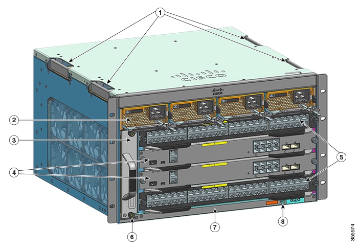
The Catalyst 9404R Switch is a four-slot modular chassis, with two redundant supervisor module slots, two line card slots with up to 96 front panel ports, one nonredundant fan tray assembly, and has a provision to accommodate up to four power supply modules.
Front View of the Catalyst 9404R Switch
The figure shows a front view of the chassis, with the major components identified:
|
1 |
Chassis handholds |
5 |
Line card slots (1 and 4) |
|
2 |
Power supply modules |
6 |
Chassis Radio Frequency ID (RFID) |
|
3 |
Fan tray assembly |
7 |
Chassis model number |
|
4 |
Supervisor module slots (2 and 3) |
8 |
System ground |
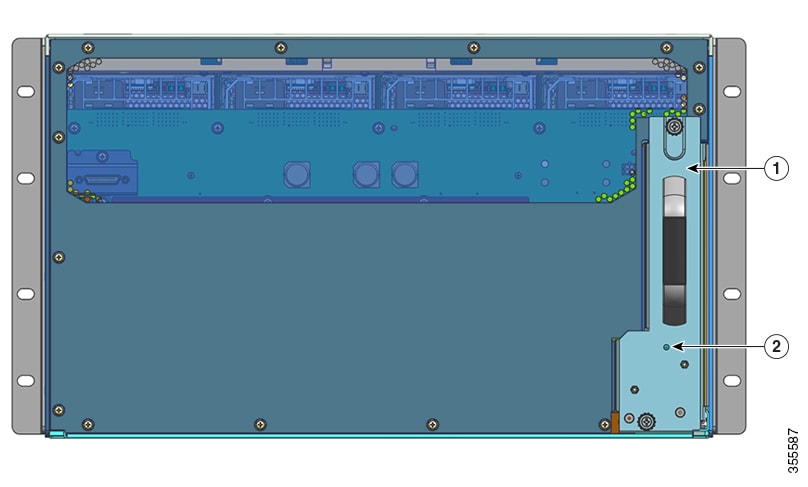
Rear View of the Catalyst 9404R Switch
The figure shows a rear view of the chassis, with the major components identified:
|
1 |
Access to remove fan tray from the rear |
2 |
Blue beacon LED on the rear panel of the fan tray (always matches the blue beacon on the front panel of the fan tray) |
|
Feature |
Description |
|---|---|
|
Product ID |
Chassis model number (add = for spare)—Cisco Catalyst 9400 Series 4 Slot Chassis(C9404R) |
|
Chassis |
Has four horizontal slots. Slots are numbered 1 (left) to 4 (right). |
|
Supervisor modules |
Supports 1+1 supervisor module redundancy for integrated resiliency. Supported model numbers (add = for spare):
Supervisor modules:
See Cisco Catalyst 9400 Series Supervisor Module Installation Note. |
|
Line cards |
Accommodates two line cards. Supported model numbers (add = for spare):
|
|
Fan tray assembly |
The switch supports a single front and rear serviceable and hot-swappable fan tray with 8 fans. Supported model number (add = for spare)—C9404-FAN See Fan Tray Assembly Overview and Fan Tray LEDs. |
|
Power supplies |
The chassis supports up to four field-replaceable AC-input and DC-input power supply modules. Supported model numbers (add = for spare):
|
|
Backplane |
With C9400-SUP-1, the backplane bandwidth is 80 Gbps. With C9400-SUP-1XL, C9400-SUP-1XL-Y, and C9400X-SUP-2, the backplane bandwidth is 240 Gbps for each payload module slot. With C9400X-SUP-2XL, the backplane bandwidth is 480 Gbps for each payload module slot. |
|
RFID Tag |
Has a built-in, front-facing, non-removable, passive RFID tag that uses Ultra High Frequency (UHF) RFID technology and requires an RFID reader with compatible software. For more information, see Radio Frequency Identification (RFID) on Cisco Catalyst 9000 Family Switches. |
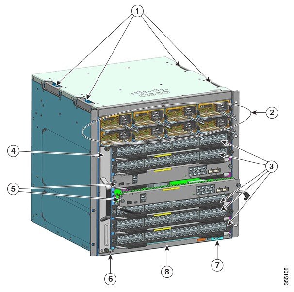
Catalyst 9407R Switch
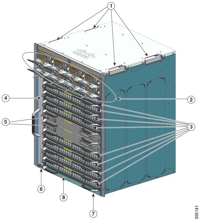
The Catalyst 9407R Switch is a seven-slot modular chassis, with two redundant supervisor module slots, five line card slots with up to 240 front panel ports, one non-redundant fan tray assembly, and a provision to accommodate up to eight power supply modules.
Front View of the Catalyst 9407R Switch
The figure shows a front view of the chassis, with the major components identified:
|
1 |
Chassis handholds |
5 |
Supervisor module slots (3 and 4) |
|
2 |
Power supply modules |
6 |
Chassis Radio Frequency ID (RFID) |
|
3 |
Line card slots (1,2, 5,6, and 7) |
7 |
System ground |
|
4 |
Fan tray assembly |
8 |
Chassis model number |
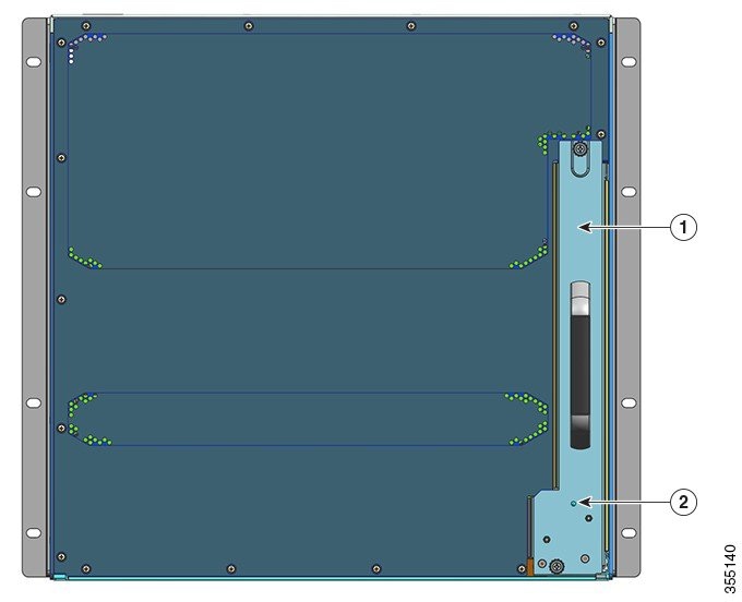
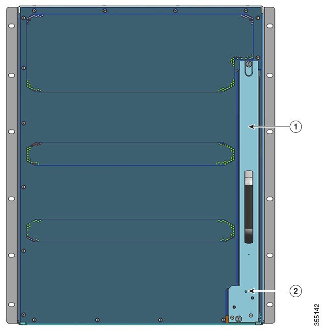
Rear View of the Catalyst 9407R Switch
The figure shows a rear view of the chassis, with the major components identified:
|
1 |
Access to remove fan tray from the rear |
2 |
Blue beacon LED on the rear panel of the fan tray (always matches the blue beacon on the front panel of the fan tray) |
|
Feature |
Description |
|---|---|
|
Product ID |
Chassis model number (add = for spare)—Cisco Catalyst 9400 Series 7 Slot Chassis(C9407R) |
|
Chassis |
Has seven horizontal slots. Slots are numbered 1 (top) to 7 (bottom). |
|
Supervisor modules |
Supports 1+1 supervisor module redundancy for integrated resiliency. Supported model numbers (add = for spare):
Supervisor modules:
See Cisco Catalyst 9400 Series Supervisor Module Installation Note. |
|
Line Cards |
Accomodates five line cards. Supported model numbers (add = for spare):
|
|
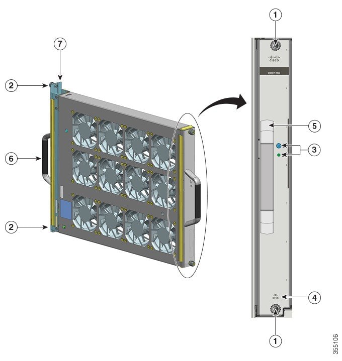
Fan tray assembly |
The switch supports a single front and rear serviceable and hot-swappable fan tray with 12 fans. Supported model number (add = for spare)—C9407-FAN See Fan Tray Assembly Overview and Fan Tray LEDs. |
|
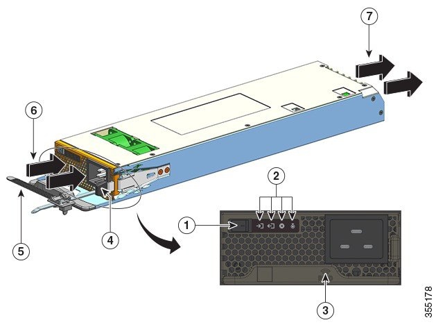
Power supplies |
The chassis supports up to eight field-replaceable AC-input and DC-input power supply modules. Supported model numbers (add = for spare):
|
|
Backplane |
With C9400-SUP-1, the backplane bandwidth is 80Gbps. With C9400-SUP-1XL and C9400-SUP-1XL-Y, the backplane bandwidth is 120 Gbps for each payload module slot. With C9400X-SUP-2, the backplane bandwidth is 240 Gbps for each payload module slot. With C9400X-SUP-2XL, the backplane bandwidth is 480 Gbps for each payload module slot. |
|
RFID Tag |
Has a built-in, front-facing, non-removable, passive RFID tag that uses Ultra High Frequency (UHF) RFID technology and requires an RFID reader with compatible software. For more information, see Radio Frequency Identification (RFID) on Cisco Catalyst 9000 Family Switches. |
Catalyst 9410R Switch
The Catalyst 9410R Switch is a ten-slot modular chassis, with two redundant supervisor module slots, eight line card slots with up to 384 1-Gigabit Ethernet front panel ports, one non-redundant fan tray assembly, and a provision to accommodate up to eight power supply modules.
Front View of the Catalyst 9410R Switch
The figure shows a front view of the chassis, with the major components identified:
|
1 |
Chassis handholds |
5 |
Supervisor module slots (5 and 6) |
|
2 |
Power supply modules |
6 |
Chassis Radio Frequency ID (RFID) |
|
3 |
Line card slots (1,2, 3, 4, 7, 8, 9 and 10) |
7 |
System ground |
|
4 |
Fan tray assembly |
8 |
Chassis model number |
Rear View of the Catalyst 9410R Switch
The figure shows a rear view of the chassis, with the major components identified:
|
1 |
Access to remove fan tray from the rear |
2 |
Blue beacon LED on the rear of the fan tray (always matches the blue beacon on the front of the fan tray) |
|
Feature |
Description |
|---|---|
|
Product ID |
Chassis model number (add = for spare)—Cisco Catalyst 9400 Series 10 Slot Chassis(C9410R) |
|
Chassis |
Has ten horizontal slots. Slots are numbered 1 (top) to 10 (bottom). |
|
Supervisor modules |
Supports 1+1 supervisor module redundancy for integrated resiliency. Supported model numbers (add = for spare):
Supervisor modules:
See Cisco Catalyst 9400 Series Supervisor Module Installation Note. |
|
Line Cards |
Accomodates eight line cards. Supported model numbers (add = for spare):
|
|
Fan tray assembly |
The switch supports a single front and rear serviceable and hot-swappable fan tray with 16 fans. Supported model number (add = for spare)—C9410-FAN See Fan Tray Assembly Overview and Fan Tray LEDs. |
|
Power supplies |
The chassis supports up to eight field-replaceable AC-input and DC-input power supply modules. Supported model numbers (add = for spare):
|
|
Backplane |
With C9400-SUP-1, C9400-SUP-1XL, and C9400-SUP-1XL-Y, the backplane bandwidth is 80Gbps for each payload module slot. With C9400X-SUP-2 the backplane bandwidth is 240 Gbps for each payload module slot. With C9400X-SUP-2XL the backplane bandwidth is 480 Gbps for each payload module slot. |
|
RFID Tag |
Has a built-in, front-facing, non-removable, passive RFID tag that uses Ultra High Frequency (UHF) RFID technology and requires an RFID reader with compatible software. For more information, see Radio Frequency Identification (RFID) on Cisco Catalyst 9000 Family Switches. |


 Feedback