Cisco Catalyst 9400 Series Line Card Installation Note
This document describes the features of all available line cards and provides information about how to correctly remove and replace a line card in the chassis.
|
C9400-LC-12QC, C9400-LC-12QC=(Spare) |
C9400-LC-48P, C9400-LC-48P= (Spare) |
|
C9400-LC-24S, C9400-LC-24S= (Spare) |
C9400-LC-48S, C9400-LC-48S= (Spare) |
|
C9400-LC-24XS, C9400-LC-24XS= (Spare) |
C9400-LC-48T, C9400-LC-48T= (Spare) |
|
C9400-LC-24XY, C9400-LC-24XY=(Spare) |
C9400-LC-48TX, C9400-LC-48TX=(Spare) |
|
C9400-LC-48H, C9400-LC-48H= (Spare) |
C9400-LC-48U, C9400-LC-48U= (Spare) |
|
C9400-LC-48HN, C9400-LC-48HN= (Spare) |
C9400-LC-48UX, C9400-LC-48UX= (Spare) |
|
C9400-LC-48HX, C9400-LC-48HX= (Spare) |
C9400-LC-48XS, C9400-LC-48XS= (Spare) |
The following table provides an overview of the compatible and incompatible supervisor modules for each available line card.
| - |
C9400-SUP-1 |
C9400-SUP-1XL |
C9400-SUP-1XL-Y |
C9400X-SUP-2 |
C9400X-SUP-2XL |
|---|---|---|---|---|---|
|
C9400-LC-12QC |
No |
No |
No |
Yes |
Yes |
|
C9400-LC-24S |
Yes |
Yes |
Yes |
Yes |
Yes |
|
C9400-LC-24XS |
Yes |
Yes |
Yes |
Yes |
Yes |
|
C9400-LC-24XY |
No |
No |
No |
Yes |
Yes |
|
C9400-LC-48H |
Yes |
Yes |
Yes |
Yes |
Yes |
|
C9400-LC-48HN |
Yes |
Yes |
Yes |
Yes |
Yes |
|
C9400-LC-48HX |
No |
No |
No |
Yes |
Yes |
|
C9400-LC-48P |
Yes |
Yes |
Yes |
Yes |
Yes |
|
C9400-LC-48S |
Yes |
Yes |
Yes |
Yes |
Yes |
|
C9400-LC-48T |
Yes |
Yes |
Yes |
Yes |
Yes |
|
C9400-LC-48TX |
No |
No |
No |
Yes |
Yes |
|
C9400-LC-48U |
Yes |
Yes |
Yes |
Yes |
Yes |
|
C9400-LC-48UX |
Yes |
Yes |
Yes |
Yes |
Yes |
|
C9400-LC-48XS |
No |
No |
No |
Yes |
Yes |
 Warning |
Statement 1071—Warning Definition IMPORTANT SAFETY INSTRUCTIONS Before you work on any equipment, be aware of the hazards involved with electrical circuitry and be familiar with standard practices for preventing accidents. Read the installation instructions before using, installing, or connecting the system to the power source. Use the statement number at the beginning of each warning statement to locate its translation in the translated safety warnings for this device. SAVE THESE INSTRUCTIONS  |
Cisco Catalyst 9400 Series Line Card Features
These tables provide a brief description of each line card module, the maximum bandwidth, minimum and maximum port densities, chassis support information, and restrictions (if any).
Gigabit and Multigigabit Ethernet Line Cards
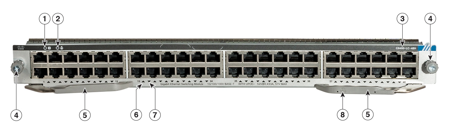
Cisco Catalyst 9400 Series 48-Port UPOE+ 10/100/1000 Module (C9400-LC-48H)
|
Description |
48-port, 10/100/1000 BASE-T Gigabit Ethernet, IEEE 802.3bt compliant module supporting up to 90 W Cisco UPOE+ on each of its 48 RJ45 ports.
|
|
Maximum Bandwidth |
48 Gbps, full duplex non-blocking traffic |
|
Minimum / Maximum Port Density1 |
|
|
Supervisor Module Compatibility |
C9400-SUP-1, C9400-SUP-1XL, C9400-SUP-1XL-Y, C9400X-SUP-2, and C9400X-SUP-2XL. Also see Overview of Supervisor Module-Line Card Compatibility. |
|
Support and Restrictions |
|
(Click on the image to see the details more clearly.)
|
1 |
STATUS LED |
5 |
Ejector levers |
|
2 |
LOCATE (blue beacon) LED |
6 |
PORT LINK LED for the port in the top row |
|
3 |
Model or product number |
7 |
PORT LINK LED for the port in the bottom row |
|
4 |
Captive installation screws |
8 |
Line card Radio Frequency Identifier (RFID) |
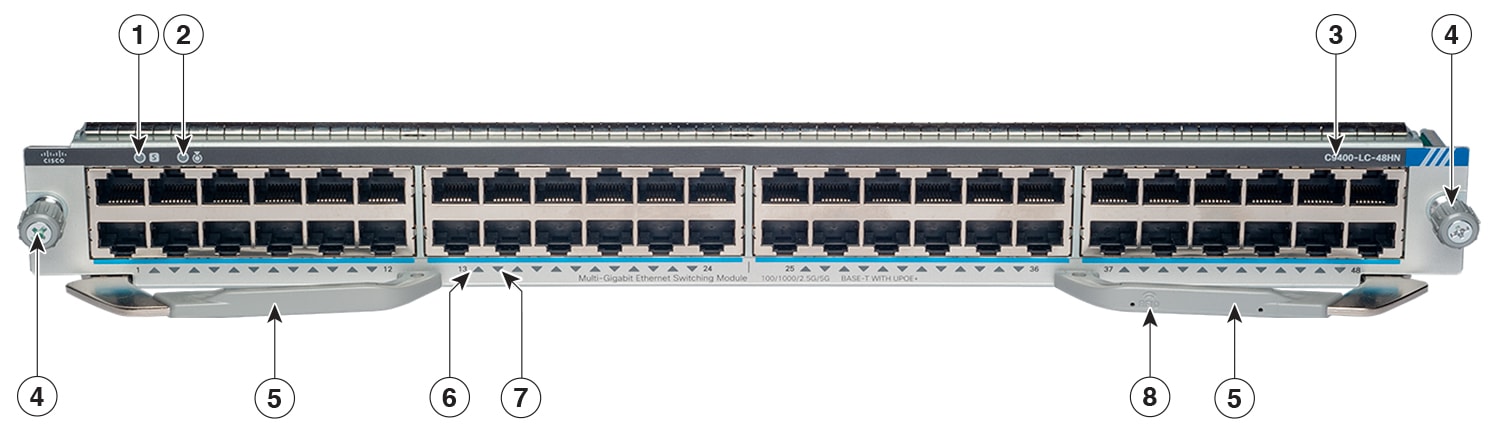
Cisco Catalyst 9400 Series 48-Port UPOE+ 100 Mbps/1G/2.5G/5G Multigigabit Module (C9400-LC-48HN)
|
Description |
48-port, 100 Mbps/1G/2.5G/5 G BASE-T Multigigabit Ethernet module supporting up to 90 W Cisco UPOE+ on each of its 48 RJ45 ports.
|
|
Maximum Bandwidth |
240 Gbps, full duplex non-blocking traffic. This value is the maximum bandwidth supported on this line card. The chassis and supervisor module combination that you use determines the final available bandwidth. For more information, see Cisco Catalyst 9400 Series Switch Line Cards Data Sheet . |
|
Minimum / Maximum Port Density2 |
|
|
Supervisor Module Compatibility |
C9400-SUP-1, C9400-SUP-1XL, C9400-SUP-1XL-Y, C9400X-SUP-2, and C9400X-SUP-2XL. Also see Overview of Supervisor Module-Line Card Compatibility. |
|
Support and Restrictions |
|
(Click on the image to see the details more clearly.)
|
1 |
STATUS LED |
5 |
Ejector levers |
|
2 |
LOCATE (blue beacon) LED |
6 |
PORT LINK LED for the port in the top row |
|
3 |
Model or product number |
7 |
PORT LINK LED for the port in the bottom row |
|
4 |
Captive installation screws |
8 |
Line card Radio Frequency Identifier (RFID) |
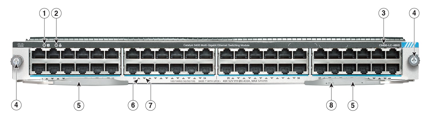
Cisco Catalyst 9400 Series 48-Port UPOE+ 100 Mbps/1G/2.5G/5G/10G Multigigabit Module (C9400-LC-48HX)
|
Description |
48-port, 100 Mbps/1G/2.5G/5G/10G BASE-T Multigigabit Ethernet module, supporting up to 90 W Cisco UPOE+ on each of its 48 RJ45 ports.
|
|
Maximum Bandwidth |
480 Gbps This value is the maximum bandwidth supported on this line card. The chassis and supervisor module combination that you use determines the final available bandwidth. For more information, see Cisco Catalyst 9400 Series Switch Line Cards Data Sheet. |
|
Minimum / Maximum Port Density3 |
|
|
Supervisor Module Compatibility |
C9400X-SUP-2 and C9400X-SUP-2XL only. Also see Overview of Supervisor Module-Line Card Compatibility. |
|
Support and Restrictions |
|
(Click on the image to see the details more clearly.)
|
1 |
STATUS LED |
5 |
Ejector levers |
|
2 |
LOCATE (blue beacon) LED |
6 |
PORT LINK LED for the port in the top row |
|
3 |
Model or product number |
7 |
PORT LINK LED for the port in the bottom row |
|
4 |
Captive installation screws |
8 |
Line card Radio Frequency Identifier (RFID) |
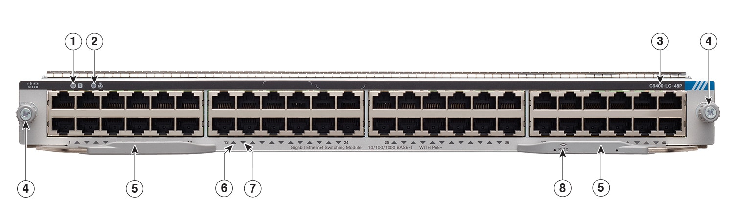
Cisco Catalyst 9400 Series 48-Port Gigabit Ethernet POE/POE+ Module (C9400-LC-48P)
|
Description |
48-port, 10/100/1000 BASE-T Gigabit Ethernet module supporting up to 30W per port on each of its 48 ports.
|
|
Maximum Bandwidth |
48 Gbps, full duplex non-blocking traffic |
|
Minimum / Maximum Port Density4 |
|
|
Supervisor Module Compatibility |
C9400-SUP-1, C9400-SUP-1XL, C9400-SUP-1XL-Y, C9400X-SUP-2, and C9400X-SUP-2XL. Also see Overview of Supervisor Module-Line Card Compatibility. |
|
Support and Restrictions |
Can be installed in any non-supervisor module slot. There are no other restrictions. |
(Click on the image to see the details more clearly.)
|
1 |
STATUS LED |
5 |
Ejector levers |
|
2 |
LOCATE (blue beacon) LED |
6 |
PORT LINK LED for the port in the top row |
|
3 |
Model or product number |
7 |
PORT LINK LED for the port in the bottom row |
|
4 |
Captive installation screws |
8 |
Line card Radio Frequency Identifier (RFID) |
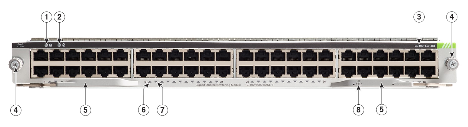
Cisco Catalyst 9400 Series 48-Port 10/100/1000 Module (C9400-LC-48T)
|
Description |
48-port, 10/100/1000 BASE-T Gigabit Ethernet module.
|
|
Maximum Bandwidth |
48 Gbps, full duplex non-blocking traffic. |
|
Minimum / Maximum Port Density5 |
|
|
Supervisor Module Compatibility |
C9400-SUP-1, C9400-SUP-1XL, C9400-SUP-1XL-Y, C9400X-SUP-2, and C9400X-SUP-2XL. Also see Overview of Supervisor Module-Line Card Compatibility. |
|
Support and Restrictions |
Can be installed in any non-supervisor module slot. There are no other restrictions. |
(Click on the image to see the details more clearly.)
|
1 |
STATUS LED |
5 |
Ejector levers |
|
2 |
LOCATE (blue beacon) LED |
6 |
PORT LINK LED for the port in the top row |
|
3 |
Model or product number |
7 |
PORT LINK LED for the port in the bottom row |
|
4 |
Captive installation screws |
8 |
Line card Radio Frequency Identifier (RFID) |
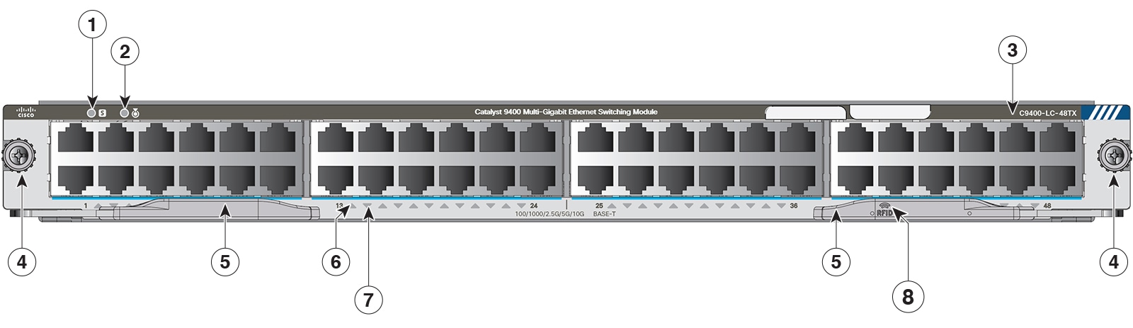
Cisco Catalyst 9400 Series 48-Port 100 Mbps/1G/2.5G/5G/10G Multigigabit Module (C9400-LC-48TX)
|
Description |
48-Port 100 Mbps/1G/2.5G/5G/10G BASE-T Multigigabit Ethernet module
|
|
Maximum Bandwidth |
480 Gbps This value is the maximum bandwidth supported on this line card. The chassis and supervisor module combination that you use determines the final available bandwidth. For more information, see Cisco Catalyst 9400 Series Switch Line Cards Data Sheet. |
|
Minimum / Maximum Port Density6 |
|
|
Supervisor Module Compatibility |
C9400X-SUP-2 and C9400X-SUP-2XL only. Also see Overview of Supervisor Module-Line Card Compatibility. |
|
Support and Restrictions |
|
(Click on the image to see the details more clearly.)
|
1 |
STATUS LED |
5 |
Ejector levers |
|
2 |
LOCATE (blue beacon) LED |
6 |
PORT LINK LED for the port in the top row |
|
3 |
Model or product number |
7 |
PORT LINK LED for the port in the bottom row |
|
4 |
Captive installation screws |
8 |
Line card Radio Frequency Identifier (RFID) |
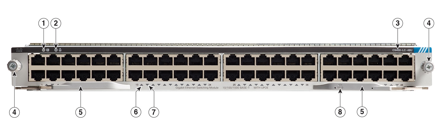
Cisco Catalyst 9400 Series 48-Port UPOE 10/100/1000 Module (C9400-LC-48U)
|
Description |
48-port, 10/100/1000 BASE-T Gigabit Ethernet module supporting up to 60W Cisco UPOE on each of its 48 RJ45 ports.
|
|
Maximum Bandwidth |
48 Gbps, full duplex non-blocking traffic. |
|
Minimum / Maximum Port Density7 |
|
|
Supervisor Module Compatibility |
C9400-SUP-1, C9400-SUP-1XL, C9400-SUP-1XL-Y, C9400X-SUP-2, and C9400X-SUP-2XL. Also see Overview of Supervisor Module-Line Card Compatibility. |
|
Support and Restrictions |
|
(Click on the image to see the details more clearly.)
|
1 |
STATUS LED |
5 |
Ejector levers |
|
2 |
LOCATE (blue beacon) LED |
6 |
PORT LINK LED for the port in the top row |
|
3 |
Model or product number |
7 |
PORT LINK LED for the port in the bottom row |
|
4 |
Captive installation screws |
8 |
Line card Radio Frequency Identifier (RFID) |
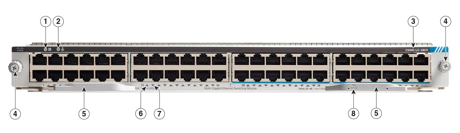
Cisco Catalyst 9400 Series 48-Port UPOE Multigigabit Module (C9400-LC-48UX)
|
Description |
48-port, UPOE Multigigabit Ethernet Module with:
|
|
Maximum Bandwidth |
240 Gbps, full duplex non-blocking traffic. This value is the maximum bandwidth supported on this line card. The chassis and supervisor module combination that you use determines the final available bandwidth. For more information, see Cisco Catalyst 9400 Series Switch Line Cards Data Sheet . |
|
Minimum / Maximum Port Density8 |
|
|
Supervisor Module Compatibility |
C9400-SUP-1, C9400-SUP-1XL, C9400-SUP-1XL-Y, C9400X-SUP-2, and C9400X-SUP-2XL. Also see Overview of Supervisor Module-Line Card Compatibility. |
|
Support and Restrictions |
|
(Click on the image to see the details more clearly.)
|
1 |
STATUS LED |
5 |
Ejector levers |
|
2 |
LOCATE (blue beacon) LED |
6 |
PORT LINK LED for the port in the top row |
|
3 |
Model or product number |
7 |
PORT LINK LED for the port in the bottom row |
|
4 |
Captive installation screws |
8 |
Line card Radio Frequency Identifier (RFID) |
Fiber Optic Ethernet Line Cards
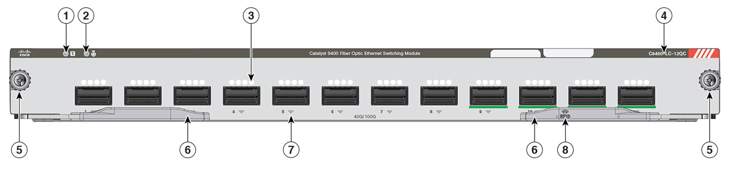
Cisco Catalyst 9400 Series 12-Port 40G/100G Module (C9400-LC-12QC)
|
Description |
12-port fiber optic Ethernet switching module.
|
|
Maximum Bandwidth |
480 Gbps This value is the maximum bandwidth supported on this line card. The chassis and supervisor module combination that you use determines the final available bandwidth. For more information, see Cisco Catalyst 9400 Series Switch Line Cards Data Sheet. |
|
Minimum / Maximum Port Density9 |
|
|
Supervisor Module Compatibility |
C9400X-SUP-2 and C9400X-SUP-2XL only. Also see: Overview of Supervisor Module-Line Card Compatibility. |
|
Support and Restrictions |
|
(Click on the image to see the details more clearly.)
|
1 |
STATUS LED |
5 |
Captive installation screws |
|
2 |
LOCATE (blue beacon) LED |
6 |
Ejector levers |
|
3 |
Vent holes for the port cage |
7 |
PORT LINK LED |
|
4 |
Model or product number |
8 |
Line card Radio Frequency Identifier (RFID) |
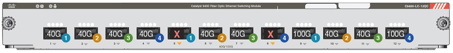
The following figure of a C9400-LC-12QC line card shows that when 100 Gbps connectivity is configured on port nos 9 and 12, port nos 5 and 8 are disabled. Accordingly, the PORT LINK LEDs for the disabled ports are amber. All the remaining ports show 40 Gbps connectivity. (The remaining ports where you can configure 100 Gbps are port nos. 10 and 11. And if you do, port nos. 6 and 7 are also disabled).
|
|
Port Group 1; port nos. 1,5, and 9. |
|
Port operating at 40 Gbps speeds |
|
Port Group 2; port nos. 2, 6, and 10 |
|
Port operating at 100 Gbps speeds |
|
|
Port Group 3; port nos. 3, 7, and 11 |
|
Port disabled because 100 Gbps port is enabled. |
|
|
|
Port Group 4; port nos. 4, 8, and 12 |
- |
- |
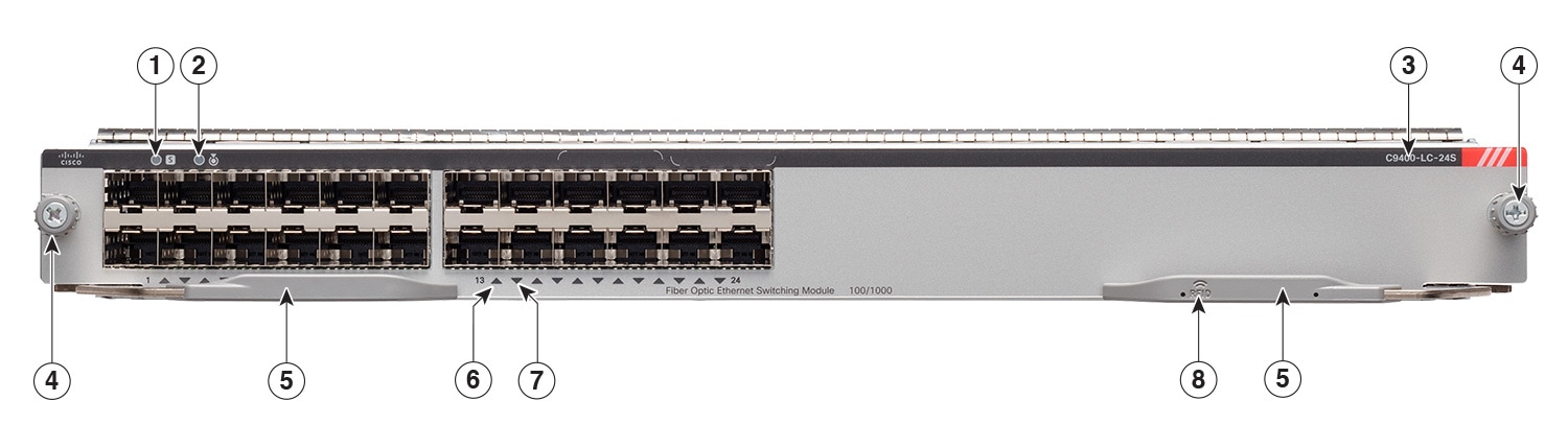
Cisco Catalyst 9400 Series 24-Port 1G SFP Module (C9400-LC-24S)
|
Description |
24-port, 1 Gigabit Ethernet SFP module.
|
|
Maximum Bandwidth |
24 Gbps, full duplex non-blocking traffic |
|
Minimum / Maximum Port Density10 |
|
|
Supervisor Module Compatibility |
C9400-SUP-1, C9400-SUP-1XL, C9400-SUP-1XL-Y, C9400X-SUP-2, and C9400X-SUP-2XL. Also see Overview of Supervisor Module-Line Card Compatibility. |
|
Support and Restrictions |
Can be installed in any non-supervisor module slot. There are no other restrictions. |
(Click on the image to see the details more clearly.)
|
1 |
STATUS LED |
5 |
Ejector levers |
|
2 |
LOCATE (blue beacon) LED |
6 |
PORT LINK LED for the port in the top row |
|
3 |
Model or product number |
7 |
PORT LINK LED for the port in the bottom row |
|
4 |
Captive installation screws |
8 |
Line card Radio Frequency Identifier (RFID) |
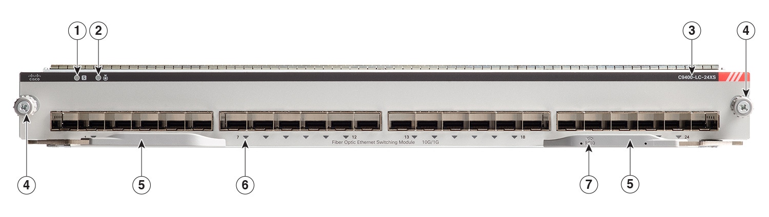
Cisco Catalyst 9400 Series 24-Port SFP/SFP+ Module (C9400-LC-24XS)
|
Description |
24 Port SFP/SFP+ 10 Gigabit Ethernet Module. These ports can be interchangeably used as 1G and 10G ports.
|
|
Maximum Bandwidth |
240 Gbps, full duplex non-blocking traffic. This value is the maximum bandwidth supported on this line card. The chassis and supervisor module combination that you use determines the final available bandwidth. For more information, see Cisco Catalyst 9400 Series Switch Line Cards Data Sheet . |
|
Minimum / Maximum Port Density11 |
|
|
Supervisor Module Compatibility |
C9400-SUP-1, C9400-SUP-1XL, C9400-SUP-1XL-Y, C9400X-SUP-2, and C9400X-SUP-2XL. Also see Overview of Supervisor Module-Line Card Compatibility. |
|
Support and Restrictions |
Can be installed in any non-supervisor module slot. There are no other restrictions. |
(Click on the image to see the details more clearly.)
|
1 |
STATUS LED |
5 |
Ejector levers |
|
2 |
LOCATE (blue beacon) LED |
6 |
PORT LINK LED |
|
3 |
Model or product number |
7 |
Line card Radio Frequency Identifier (RFID) |
|
4 |
Captive installation screws |
- |
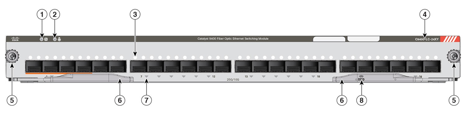
Cisco Catalyst 9400 Series 24-Port 10G/25G Module (C9400-LC-24XY)
|
Description |
24-port fiber optic Ethernet switching module.
|
|
Maximum Bandwidth |
480 Gbps This value is the maximum bandwidth supported on this line card. The chassis and supervisor module combination that you use determines the final available bandwidth. For more information, see Cisco Catalyst 9400 Series Switch Line Cards Data Sheet. |
|
Minimum / Maximum Port Density12 |
|
|
Supervisor Module Compatibility |
C9400X-SUP-2 and C9400X-SUP-2XL only. Also see: Overview of Supervisor Module-Line Card Compatibility. |
|
Support and Restrictions |
|
(Click on the image to see the details more clearly.)
|
1 |
STATUS LED |
5 |
Captive installation screws |
|
2 |
LOCATE (blue beacon) LED |
6 |
Ejector levers |
|
3 |
Vent holes for the port cage |
7 |
PORT LINK LED |
|
4 |
Model or product number |
8 |
Line card Radio Frequency Identifier (RFID) |
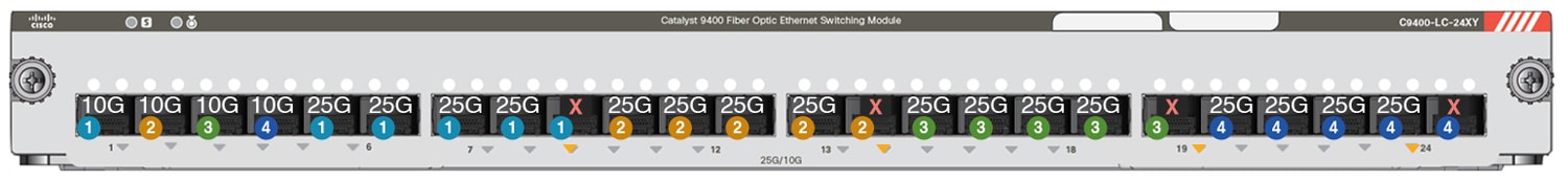
The following figure of a C9400-LC-24XY line card shows the four port groupings. It also shows the following for each port group: 4 ports with 25 Gbps connectivity and 1 port with 10 Gbps connectivity. With each port group providing up to 120 Gbps, one port in each port group is not used .
|
|
Port Group 1; port nos. 1,5, 6, 7, 8, and 9. |
|
Port operating at 10 Gbps speeds. |
|
Port Group 2; port nos. 2, 10, 11, 12, 13 and 14. |
|
Port operating at 25 Gbps speeds. |
|
|
Port Group 3; port nos. 3, 15, 16, 17, 18, and 19. |
|
Port not used. |
|
|
|
Port Group 4; port nos. 4, 20, 21, 22, 23, and 24. |
- |
- |
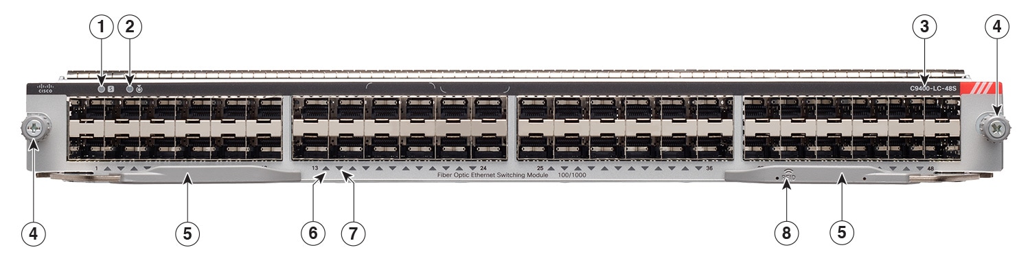
Cisco Catalyst 9400 Series 48-Port 1G SFP Module (C9400-LC-48S)
|
Description |
48-port, 1 Gigabit Ethernet SFP module.
|
|
Maximum Bandwidth |
48 Gbps, full duplex non-blocking traffic. |
|
Minimum / Maximum Port Density13 |
|
|
Supervisor Module Compatibility |
C9400-SUP-1, C9400-SUP-1XL, C9400-SUP-1XL-Y, C9400X-SUP-2, and C9400X-SUP-2XL. Also see Overview of Supervisor Module-Line Card Compatibility. |
|
Support and Restrictions |
Can be installed in any non-supervisor module slot. There are no other restrictions. |
(Click on the image to see the details more clearly.)
|
1 |
STATUS LED |
5 |
Ejector levers |
|
2 |
LOCATE (blue beacon) LED |
6 |
PORT LINK LED for the port in the top row |
|
3 |
Model or product number |
7 |
PORT LINK LED for the port in the bottom row |
|
4 |
Captive installation screws |
8 |
Line card Radio Frequency Identifier (RFID) |
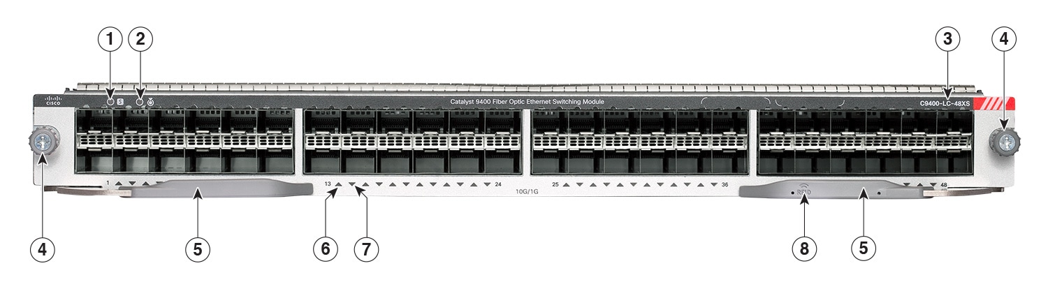
Cisco Catalyst 9400 Series 48-Port SFP/SFP+ Module (C9400-LC-48XS)
|
Description |
48 Port SFP/SFP+ Module. These ports can be used interchangeably, as 1G or 10G ports.
|
|
Maximum Bandwidth |
480 Gbps This value is the maximum bandwidth supported on this line card. The chassis and supervisor module combination that you use determines the final available bandwidth. For more information, see Cisco Catalyst 9400 Series Switch Line Cards Data Sheet. |
|
Minimum / Maximum Port Density14 |
|
|
Supervisor Module Compatibility |
C9400X-SUP-2 and C9400X-SUP-2XL only. Also see Overview of Supervisor Module-Line Card Compatibility. |
|
Support and Restrictions |
|
(Click on the image to see the details more clearly.)
|
1 |
STATUS LED |
5 |
Ejector levers |
|
2 |
LOCATE (blue beacon) LED |
6 |
PORT LINK LED for the port in the top row |
|
3 |
Model or product number |
7 |
PORT LINK LED for the port in the bottom row |
|
4 |
Captive installation screws |
8 |
Line card Radio Frequency Identifier (RFID) |
Cisco Catalyst 9400 Series Line Card LEDs
|
LED |
LED Color |
Meaning |
|---|---|---|
 STATUS |
Green |
All diagnostic tests have passed and the module is operational. |
|
Amber |
The module is booting or running diagnostics or the module is disabled. |
|
|
Red |
A test other than an individual port test has failed. On some modules, this LED turns red immediately after the system is powered on, until the software boot process begins. |
|
|
Off |
The module is disabled or is not powered up. |
|
 LOCATE |
Blue |
Identifies the module receiving the beacon signal. |
 PORT LINK |
Green |
Port link is up but there is no packet activity. |
|
Blinking Green |
Port link is up and indicating packet activity. |
|
|
Amber |
Port link is disabled by the user, that is, administratively down. |
|
|
Blinking Amber |
Hardware (PHY) has detected a faulty port link. |
|
|
Alternating Green and Amber |
Error packets are being detected on the port link. The error packets could be bad Cyclic Redundancy Check (CRC) packets, jumbo packets, and so on. |
|
|
Off |
No signal is detected, the link is down, or the port is not connected. |
Removing and Replacing Line Cards
All Cisco Catalyst 9400 Series line cards support hot swapping, which lets you install, remove, replace, and rearrange line cards without powering off the system. When the system detects that a line card has been installed or removed, it runs diagnostic and discovery routines automatically, acknowledges the presence or absence of the module, and resumes the system operation with no operator intervention.
Warning |
Statement 9001—Product Disposal Ultimate disposal of this product should be handled according to all national laws and regulations. |
Identifying Line Card Slots
The slot numbers on the fan tray front panel help you easily identify the line card slots or the non-supervisor slots. Install line cards only in these slots.
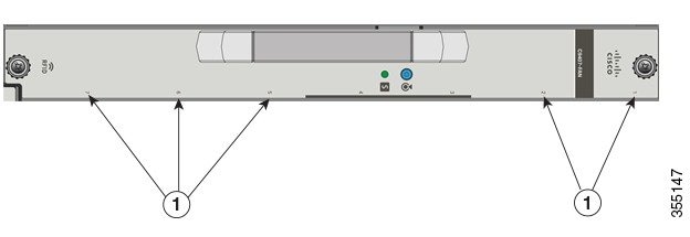
|
1 |
Line card slots numbered 1, 2, 5, 6, and 7.
|
- |
- |
Required Tools
You will need these tools to install or remove supervisor modules and line cards:
-
Your own ESD-prevention equipment or the disposable grounding wrist strap included with all upgrade kits, field-replaceable units (FRUs), and spares.
-
Antistatic mat or antistatic bag
-
Number 1 and number 2 Phillips screwdrivers for the captive installation screws on most modules
-
3/16-inch flat-blade screwdriver for the captive installation screws on some modules
Removing a Line Card
Warning |
Statement 1051—Laser Radiation Invisible laser radiation may be emitted from disconnected fibers or connectors. Do not stare into beams or view directly with optical instruments. |
Before you begin
Procedure
|
Step 1 |
Disconnect any network interface cables attached to the line card's ports. |
||||
|
Step 2 |
If the module is equipped with removable optical transceivers, immediately install dust plugs into the transceiver’s optical bores. This prevents possible dust contamination, which can affect port performance. |
||||
|
Step 3 |
With a Phillips screwdriver, completely loosen the two captive screws located at each end of the module faceplate. |
||||
|
Step 4 |
Grasp the left and right ejector levers and simultaneously pivot the levers outward to eject the module from the backplane connector. 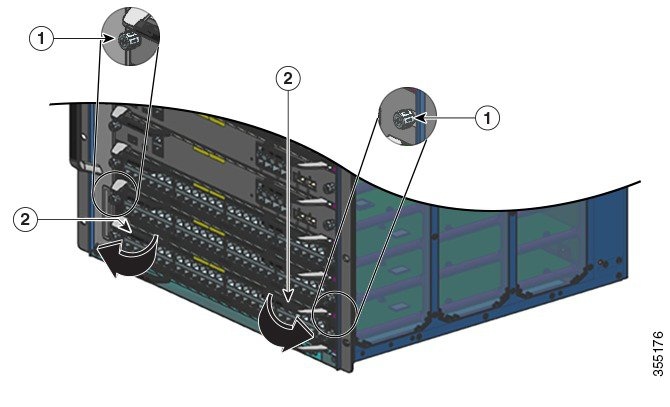
|
||||
|
Step 5 |
Grasp the module front panel with one hand, and place your other hand under the module (on the metal carrier) to support and guide it out of the slot. Do not touch the printed circuit boards or connector pins. |
||||
|
Step 6 |
Pull the module straight out of the slot, keeping one hand under the module to support it. |
||||
|
Step 7 |
Immediately place the removed module on an antistatic mat, in an antistatic bag, or install it in another slot. |
||||
|
Step 8 |
If the slot is to remain empty, install a blank module filler plate to keep dust out of the chassis, maintain proper airflow through the chassis, preserve electromagnetic interference (EMI) integrity, and to prevent exposure to high current inside the chassis.
|
Installing a Line Card
Warning |
Statement 1051—Laser Radiation Invisible laser radiation may be emitted from disconnected fibers or connectors. Do not stare into beams or view directly with optical instruments. |
 Caution |
To prevent electrostatic discharge (ESD) damage, handle modules by the carrier edges only. |
 Note |
|
Procedure
|
Step 1 |
Take the necessary precautions to prevent ESD damage. Wear a grounded ESD wrist strap while handling the modules, and keep them in ESD-protective bags when they are not installed in a chassis. |
||||||||
|
Step 2 |
Choose a slot for the module. Verify that you have enough clearance for any interface equipment that you are connecting directly to the line card ports. |
||||||||
|
Step 3 |
Loosen the captive installation screws that secure the existing module or the blank module filler plate in the slot you want to use. |
||||||||
|
Step 4 |
Remove the existing module and immediately place it on an antistatic mat or in an antistatic bag. If you are removing a blank module filler plate, set the blank module filler plate aside for future use. |
||||||||
|
Step 5 |
Remove the new module from its packaging being careful to handle the module using only the module’s metal tray or the front panel. Do not touch the printed circuit board or the connector pins. |
||||||||
|
Step 6 |
Pivot the two module ejector levers out away from the module faceplate. |
||||||||
|
Step 7 |
Position the module in front of the chassis slot and align the edges of the printed circuit board with the slot guides on the sides of the switch chassis. |
||||||||
|
Step 8 |
Carefully slide the module into the slot until the notches on both ejector levers engage the chassis sides (the ejector levers start to pivot in towards the faceplate). 
|
||||||||
|
Step 9 |
Using your thumb and forefinger of each hand, simultaneously pivot in both ejector levers, to fully seat the module in the backplane connector. 
|
||||||||
|
Step 10 |
Use a screwdriver to tighten the captive installation screw on each end of the module faceplate. |
||||||||
|
Step 11 |
Install any necessary transceivers in the module ports. Installation instructions along with safety warnings for the various types of transceivers can be found at the following URL: https://www.cisco.com/en/US/products/hw/modules/ps5455/prod_installation_guides_list.html |
||||||||
|
Step 12 |
Attach any necessary network interface cables or other devices to the interface ports. |
||||||||
|
Step 13 |
Check the status of the module as follows:
|
||||||||
|
Step 14 |
If the module is not operational, try reseating it in the slot. If the module is still not operational, contact your customer representative. |
What to do next
Related Documentation
For related installation and configuration information, refer to the following:
Release and General Information
Release Notes: https://www.cisco.com/c/en/us/support/switches/catalyst-9400-series-switches/products-release-notes-list.html
Provides an overview of the hardware and software features introduced in every release, unsupported features, important restrictions and limitations, and open and resolved caveats with the software.
Hardware Documentation
-
Hardware Installation Guide: https://www.cisco.com/c/en/us/td/docs/switches/lan/catalyst9400/hardware/install/b_c9400_hig.html
Provides a functional overview of the switch, describes how to install and rack-mount the switch, and make connections to the switch. It describes how to install the power supplies and how to replace the fan tray assembly. It also includes technical specifications and troubleshooting guidance.
-
Supervisor Module Installation Note: https://www.cisco.com/c/en/us/td/docs/switches/lan/catalyst9400/hardware/sup_install/b-c9400-sup-note.html
Provides an overview of the available supervisor modules, major features, chassis compatibility information, slot restrictions, and describes how to correctly install and uninstall a supervisor module.
-
Line Card Installation Note: https://www.cisco.com/c/en/us/td/docs/switches/lan/catalyst9400/hardware/sw_mod_install/b-c9400-mod-note.html
Provides an overview of the supported line cards, major features, describes how to correctly install and uninstall a line card, and transceiver support.
-
Regulatory Compliance & Safety Information Document: https://www.cisco.com/c/dam/en/us/td/docs/switches/lan/catalyst9400/hardware/regulatory/RCSI-0315-book.pdf
Consolidated list of safety warnings relevant to Catalyst 9400 Series Switches (all chassis models), supervisor modules, line cards and any other hardware components.
Software Documentation
-
Software Configuration Guide: https://www.cisco.com/c/en/us/support/switches/catalyst-9400-series-switches/products-installation-and-configuration-guides-list.html
Provides detailed software configuration information for the features supported on the switch. These guides are release-specific.
-
Command Reference: https://www.cisco.com/c/en/us/support/switches/catalyst-9400-series-switches/products-command-reference-list.html
Provides command syntax, command history and usage guidelines for the Cisco IOS commands supported on the switch. These guides are release-specific.
 Feedback