Troubleshooting

About this Section

This chapter describes how to perform basic troubleshooting on Cisco Catalyst 9400 Series Switches. Problems with the initial startup are often caused by a line card that has become dislodged from the backplane or a power cord that is disconnected from the power supply.

Although temperature conditions above the maximum acceptable level rarely occur at initial startup, some environmental monitoring functions are included in this chapter because they also monitor power supply output voltages.


Note


This chapter covers only the chassis component hardware aspects of troubleshooting. For software configuration issues, refer to the software configuration guide


System Boot Verification

When the initial system boot is complete, verify the following:

  • That the system software boots successfully

    Hook up a terminal and view the startup banner. Use an RJ-45-to-RJ-45 rollover cable to connect the console port to a PC with terminal emulation software set for 9600 baud, 8 data bits, no parity, and 1 stop bit. Watch for any system messages after startup.

  • That the power supplies are supplying power to the system

    The power supply’s LED should be green. Use the show environment Cisco IOS command to view power supply activity.

  • That the system fan assembly is operating

    Listen for fan activity. The Fan tray LED should be green during operation. Use the show environment Cisco IOS command to view fan tray activity.

  • That the supervisor and all line cards are installed properly in their slots, and that each initialized without problems.

If all of these conditions are met and the hardware installation is complete, refer to the software configuration guide and command reference publications for your switch so that you can troubleshoot the software.

If any of these conditions is not met, use the procedures in this chapter to isolate and, if possible, resolve the problem.

Using LEDs to Identify Startup Problems

The key to success when troubleshooting the system is to isolate the problem to a specific system component. Your first step is to compare what the system is doing with what it should be doing. All system states in the startup sequence are indicated by LEDs. By checking the LEDs, you can determine when and where the system failed in the startup sequence. If you have problems after the switch is on, refer to the following subsystem troubleshooting information and the configuration procedures in the software configuration guide for your switch.

After you connect the power cords to your switch, follow these steps to determine whether your system is operating properly:

Procedure


Step 1

Check the power supply LEDs:

The INPUT LED should turn green when power is applied to the supply. The LED should remain on during normal system operation.

If the INPUT LED does not light, or if the LED labeled FAIL lights, see the “Troubleshooting the Power Supply” section.

Note


If a power supply is installed and not connected to a power source, power supply LEDs are not lit.

Step 2

Listen for the system fan assembly. The system fan assembly should be operating whenever system power is on. If you do not hear it when the switch is on, see the “Troubleshooting the Fan Assembly” section.

Step 3

Check that the LEDs on the supervisor module light as follows:

  • The STATUS LED flashes amber once and stays amber during diagnostic boot tests.

    • It turns green when the module is operational (online).

    • If the system software is unable to start up, this LED turns red.

      If the LED is red, connect a console to the management port and use the show environment command to check for possible problems.

  • The MANAGEMENT LED turns green when the module is operational (online) and a link is established with another network device. If no signal is detected, the LED turns off.

  • If there is a problem with the supervisor module, try reseating the supervisor module in the chassis and restarting the switch. For more troubleshooting information, see the “Troubleshooting Supervisor Modules” section.

  • Verify that the STATUS LEDs on each line card is green when the supervisor module completes initialization.

    This LED indicates that the supervisor module and line cards are receiving power, have been recognized by the supervisor module, and contain a valid Flash code version. However, this LED does not indicate the state of the individual interfaces on the line cards. If a STATUS LED is red, try reseating the line card or supervisor module and restarting the switch. For more information, see the “Troubleshooting Line Cards” section. If you determine that the line card is not operating, contact Cisco TAC as described in the “Some Problems and Solutions” section.
  • If the boot information and system banner are not displayed, verify that the terminal is set for 9600 baud, 8 data bits, no parity, and 1 stop bit and connected properly to the console port.


System Messages

System messages appear on the console if you have enabled console logging or appear in the syslog if you have enabled syslog. Many messages are for informational purposes only and do not indicate an error condition. Enter the show logging command to display the log messages. To better understand a specific system message, refer to the system message guide for your software release.

Troubleshooting a Power Supply Module

Useful Cisco IOS Commands - Power Supply

You may use the following Cisco IOS commands in the priviledged EXEC mode, to monitor the status, load, and activity of a power supply module.

  • Switch# show power detail

    If FAIL LED is red, the show power command output reports the power supply module as faulty.

  • Switch# show idprom power-supply slot-number
  • Switch# show module

    If the show module command output shows a message that states "not enough power for module," check the corresponding power supply specifications here: Power Supply Specifications. There may be a problem with the power source itself.

Troubleshooting an AC-Input Power Supply

To help isolate a power subsystem problem, follow these steps:

Procedure


Step 1

The INPUT should be solid green for normal operation. If the INPUT LED is off, take the following steps:

  1. Ensure that the power supply is flush with the back of the chassis by gently inserting it all the way in until it stops. You should feel the retaining metal latch, on its right side, click into place. The unit should not be removable without depressing this latch towards it.

    Note


    You should be unable to remove the power supply from the system when the power cord is fully inserted and installed with the cord retainer.

  2. Unplug the power cord by loosening the cord retainer and physically reinstalling the power supply, plug in the power cord and tighten the cord retainer around it.

  3. If the INPUT LED remains off, there may be a problem with the AC source or the power cable connection. Also check the circuit breaker of the AC source. Connect the power cord to another power source if one is available. Verify that the source power is within the acceptable specifications of the power supply.

  4. If the LED remains off after you connect the power supply to a new power source, replace the power cord.

  5. If the LED still fails to light when the switch is connected to a different power source with a new power cord, the power supply is probably faulty. You may need to replace the power supply.

Step 2

The OUTPUT LED should be solid green for normal operation. Blinking green indicates that the unit is asleep in standby mode.

Step 3

If the FAIL LED is red, take the following steps:

  1. Remove the power supply from the bay and visually inspect the rear of the power supply module connector. If there is no damage, try installing it in another empty power supply bay, if available. Do not touch the back of the power supply module during this inspection. If the OUTPUT LED turns green, the problem may lie with the first power supply bay and not the power supply module. Call Cisco Technical Assistance Center (Cisco Support) for further instructions.

  2. If a second power supply is available, install it in the second power supply bay.

  3. Check that the INPUT LED is on for the additional power supply. Check that the FAIL LED is off.

  4. If the LEDs are not on, repeat the previous procedure to troubleshoot the second power supply

Step 4

Contact Cisco Technical Assistance Center.

If you are unable to resolve the problem, or if you determine that either a power supply or backplane connector is faulty, contact Call Cisco Technical Assistance Center (Cisco Support) for instructions.


Troubleshooting a DC-Input Power Supply

To help isolate a power subsystem problem, follow these steps:

Procedure


Step 1

The INPUT LED should be solid green for normal operation. If the INPUT LED is off, perform the following steps:

  1. Check the DC source.

    1. Check that the circuit breaker of the DC source is ON.

    2. Connect the cables to another power source if one is available. Verify that the source power is within the acceptable specifications of the power supply.

    3. Check that you have connected both the DC inputs to a suitable DC source. The power supply module is not designed to function with just one DC input.

    4. If you are using a single source, check that it is capable of providing 3500 W of DC-input power. If it is two different sources, check that each source is able to provide 1750 W of DC-input power.

    5. Ensure that the DC source is capable of providing a minimum of -40 V to the input terminals of the DC power supply module. .

  2. Check the DC-input cable connections

    1. Check that the lugs are fastened properly and torqued to between 2.0 and 2.8 Nm.

    2. Check that the polarity of the DC-input cables is not reversed. For more information, see Power Connection Guidelines for DC-Powered Systems

    3. If you are using a separate source for each DC input, check that you have not crossed the cables (reversed positive or negative inputs).

Note


If the INPUT LED still fails to light, the power supply module is probably faulty. You may have to replace it.

Step 2

The OUTPUT LED should be solid green for normal operation. Blinking green indicates that the unit is asleep in standby mode. If the OUTPUT LED is off, perform the following steps:

  1. Check if you have pressed the power button for two seconds to turn on the module.

  2. Check if the INPUT LED is on; if it is not, follow the steps to troubleshoot the INPUT LED first (Step 1).

  3. Check if the release latch has been pushed in to lock it.

Step 3

The FAIL LED should be OFF for normal operation. If the FAIL LED is red, perform the following steps:

  1. Check the power button.

    If the power button on the front panel of the module is turned off after DC input is applied, the FAIL LED will be solid red until you press the power button for two seconds to turn it on again.

  2. Inspect the module.

    Remove the power supply module from the bay and visually inspect the rear of the power supply module connector. If there is no damage, try installing it in another empty power supply bay, if available. Do not touch the back of the power supply module during this inspection. If the OUTPUT LED turns green, the problem may lie with the first power supply bay and not the power supply module. Call Cisco Technical Assistance Center (Cisco Support) for further instructions.

  3. Test with another spare.

    If a second power supply module is available, install it in the second power supply bay.

    1. Check that the INPUT LED is on for the second power supply, and that the FAIL LED is off.

    2. If the INPUT LEDs for this second power supply is not on, repeat the procedure to troubleshoot INPUT LED of the second power supply (Step 1).

    3. If the FAIL LED for this second power supply is on, repeat steps to troubleshoot the FAIL LED (Step 3).

Step 4

Contact Cisco Technical Assistance Center.

If you are unable to resolve the problem, or if you determine that either a power supply or backplane connector is faulty, contact Call Cisco Technical Assistance Center (Cisco Support) for instructions.


Restoring the Default Mode of the Power Button for a DC Power Supply Module

If you are unsure of whether the power button of a DC-input power supply module is in the auto-on mode or the protected mode, you can restore the default mode (auto-on). Begin by checking the following:

  1. The number of power supply modules currently configured

  2. If the 3.3-VDC standby output is active (applied)

Depending on the conditions that apply, take the required action to restore the default mode of the power button, as shown in the following table:

Condition

Action Required to Restore Default Mode of the Power Button

Only one power supply module is configured, and it is a DC-input power supply module.

  1. Switch off the DC circuit breaker for at least three seconds.

  2. Switch on the DC circuit breaker.

    The FAIL LED is illuminated for two to three seconds.

Result: The power supply module enables output power automatically, and the power button is in auto-on mode.

Multiple power supply modules are configured (AC and DC input).

and

3.3-VDC standby output of the power supply modules (AC and DC input) is inactive.

  1. Switch off the DC circuit breaker of the affected power supply module for at least three seconds.

  2. Switch on the DC circuit breaker of the affected DC-input power supply module.

    The FAIL LED is illuminated for two to three seconds.

Result: The power button is in auto-on mode.

Multiple power supply modules are configured (AC and DC input).

and

3.3-VDC standby outputs of one of the power supply modules is active1.

  1. Press the power button of the affected DC-input power supply module for two seconds, to turn it off.

  2. Switch off the circuit breaker of the affected DC-input power supply module.

  3. Remove and reinsert the DC-input power supply module after having its DC input physically disconnected or disabled for at least three seconds.

  4. Switch on the DC circuit breaker of the affected DC-input power supply module.

Result: The power button is in auto-on mode.

1 Regardless of whether one or more AC-input or DC-input power supply modules in the system is off or on, if AC-input or DC-input power is applied, 3.3-VDC standby is active and distributed to all power supply modules in the chassis.

Troubleshooting the Fan Tray Assembly


Note


All fans must be operating or a failure will occur.


Environmental problems may initially appear to be problems with the fan tray. To help isolate a fan assembly problem, follow these steps:

Procedure


Step 1

Check the STATUS LED on the fan tray

  • If the LED is off and the rest of the system is functioning, the fan tray is not getting power or is not seated correctly on the backplane.

  • If the LED is green, the fans are operating normally. There may be conditions impairing fan performance, but they are minimal in impact.

  • If the LED is amber, one fan has failed.

  • If the LED is red, two or more fans have failed. If LED remains red for more than one minute, fans are pushed to operate at full speed, causing loud noise levels.

  • If the LED is off and the fans are not running at all, make sure to insert it all the way and to tighten the screws.

    If you have serviced the fan from the front, ensure that the captive installation screws in the rear are also sufficiently tight. If you have serviced the fan from the rear, ensure that the captive installation screws in the front are also sufficiently tight.

    Fans may take a few seconds to start ramping up in speed.

Step 2

Connect a terminal and determine the fan tray status shown by the show environment status privileged EXEC command command.

The status and sensor columns read good—the STATUS is green

The status and sensor columns read marginal—the STATUS is amber, one fan has failed.

The status and sensor columns read bad—the STATUS is red, two or more fans have failed.

Step 3

Determine whether the airflow is restricted; verify that the minimum rack clearance requirements are met. See Air Flow.

Step 4

Determine whether the power supply is functioning properly.

Step 5

Verify that the fan tray assembly is properly seated, by loosening the captive installation screws, removing the fan assembly, and reinstalling it.

Note


There is a time constraint when you remove and replace the fan tray in a system that is powered on. The system can safely run without a fan tray only for 2 minutes. There is no time constraint in a system that is not powered on.

Step 6

Restart the system.

Step 7

Verify that all fans are operating. You should hear the fans at system start.


What to do next

If the system is still detecting a fan assembly failure, check for details using the Cisco IOS commands, save the logs, and contact the Cisco TAC for assistance.

Useful Cisco IOS Commands - Fan Tray Assembly

You may use the following Cisco IOS commands in the priviledged EXEC mode, to diagnose fan tray problems.

  • To turn the blue beacons on:

    Switch# hw-module beacon fan-tray on
    

    To turn the blue beacons off:

    Switch# hw-module beacon fan-tray off
    
  • To display fan tray speeds:

    Switch# configure terminal
    Switch(config)# service internal
    Switch(config)# end
    Switch# test platform hardware chassis fantray {nebs-mode | service-mode | write }
  • To display fan tray status:

    Switch# show environment status
  • To manually enter the NEBS mode:

    Switch# configure terminal
    Switch(config)# service internal
    Switch(config)# end
    Switch# test platform hardware chassis fantray nebs-mode on
    

    To turn-off the NEBS mode:

    Switch# configure terminal
    Switch(config)# service internal
    Switch(config)# end
    Switch# test platform hardware chassis fantray nebs-mode off
    

Troubleshooting High Temperature Alarms

A dirty air filter may cause overheating of the switch. Multiple board temperature sensors trigger alarm in case of overheating caused by dirty filter.

Inspect the air filter if the high temperature alarm goes off.

Cleaning and Replacing Air Filters

The air filter removes dust from the room air drawn into the switch by the cooling fans. Once a month (or more often in industry environments), you should examine the air filter. If the filter appears dirty, you can either vacuum or replace it. If the filter appears worn or torn, dispose of it in a responsible manner and install a replacement air filter.


Note


We recommend that you change the air filter every three months. However, examine the air filter once a month (or more often in dusty environments) and replace it if it appears to be excessively dirty or damaged. To comply with Telecordia GR-63-Core standard air filter requirements for NEBS deployments, the air filter must be replaced, not cleaned


Troubleshooting the Line Card

Each line card has one STATUS LED that provides information about the module and one numbered PORT LINK LED for each port on the module. Refer to Cisco Catalyst 9400 Series Line Card LEDs to ascertain the meaning of the LED colors.

Useful Cisco IOS Commands - Line Cards

The show module command provides information that is useful in solving problems with ports on individual modules.

Some problems can be solved by resetting the line card. Power cycle the chassis - this resets, restarts, and power cycles the line card.

Troubleshooting Supervisor Modules

This section only addresses problems with hardware. Problems with features or configuration are not covered here. Refer for your software configuration guide and release notes for information on configuring features or identifying known problems.

Supervisor Module LEDs

  • Check the LEDs on your supervisor and compare them to the described LED behaviors. See Cisco Catalyst 9400 Series Supervisor Module LEDs

  • The Supervisor Module STATUS LED turns either amber or red under the following conditions:

    • Power supply failure (not the same as removal of power supply)

    • Power supply fan failure

    • Removal or failure of fan tray

    • Mismatched power supplies in the chassis

Standby Supervisor Engine Problems

  • Switch# show module

    If the standby supervisor module is not online or status indicates “other” or “faulty” in the output of the show module command or an amber status LED, create a console connection to the standby supervisor and check if it is in ROMMON mode or in continuous reboot. If the standby supervisor is in either of these two states, refer to the System Management > Troubleshooting the Software Configuration section of the Software Configuration Guide

  • Make sure that the supervisor module properly seats in the backplane connector and that you have completely screwed down the captive screws for the supervisor module.

  • Switch# redundancy reload peer

    In order to determine whether the standby supervisor module is faulty, enter the redundancy reload peer command from the active supervisor and through the console to the standby supervisor. Observe the bootup sequence in order to identify any hardware failures. Currently, the active supervisor module cannot access the power-on diagnostics results of the standby supervisor module.

  • Make sure that these configurations are synchronized between the active and redundant supervisor modules:

    • Startup configuration

    • Boot variable

    • Configuration register

    • Calendar

    • VLAN database

If a software upgrade is performed on both the active and standby supervisor module, verify that both supervisor modules are running the same new software image. If the software images are not the same, upgrade the software image. Use the procedure in the software configuration guide for your release.

If the standby supervisor still does not come on line, create a service request with Cisco Technical Support. Use the log of the switch output that you collected from the previous troubleshooting steps.

Switch Self Reset

If the switch has reset or rebooted on its own, verify that the power source for the switch did not fail. If you use an uninterruptable power supply (UPS), make sure that the UPS does not have any problems.

The switch might have had a software crash. Enter the more crashinfo:data command to display the crash information including date and time of the last time that the switch crashed. To display the standby supervisor engine crash data, enter the more slavecrashinfo:data command. Crash data is not present if the switch has not crashed.

If the output indicates a software crash at the time that you suspect that the switch rebooted, the problem can be something other than a hardware failure. Contact Cisco Technical Support with the output of these commands:

  • show tech-support

  • show logging

  • more crashinfo:data

Cannot Connect to a Switch Through the Console Port

Make sure you are using the correct type of cable and that the cable pinouts are correct for your supervisor module

Make sure the terminal configuration matches the switch console port configuration—default console port settings are 9600 baud, 8 data bits, no parity, 1 stop bit.

To access the switch through the console port, the following must match

  • The BAUD environment variable in the ROMMON

  • Console port speed

  • Start-up configuration


Note


The factory default for the the BAUD environment variable is an explicit setting: BAUD variable=9600. This variable also defaults to 9600 (implicit setting) when a variable is not set explicitly.


During initial switch configuration, proceed as follows:

  1. Ensure that the terminal configuration matches the switch console port speed configuration. The following example uses a Cisco switch as the console, and the console port number is 8. Enter the appropriate console port number when you configure the console port speed.

    Switch# configure terminal
    Enter configuration commands, one per line.  End with CNTL/Z.
    Switch(config)#line 8
    Switch(config-line)# speed 9600
    
  2. Access ROMMON prompt and verify the BAUD setting on the switch—Connect the console to system and while system is booting, after you see the the prompt, press CTRL+C to stop booting and access ROMMON prompt. In the example, the factory default setting is retained.

    rommon 1> set 
    BAUD=9600
    <output truncated>
    

    If you want to change this setting, you can do so now

    rommon 2> set BAUD <enter new speed>

    If you enter a new speed, you must redo step 1 because you will lose ROMMON access immediately after setting a new speed.

  3. Boot the image.

    rommon 4> boot

    During bootup, the BAUD rommon setting on the active supervisor is automatically synced to the standby.

  4. Save the running configuration:

    Switch# copy system:running-config nvram:startup-config

    When the BAUD rommon variable is set in ROMMON mode, this value is extracted for the line console in the running configuration, when the system reloads. However, when the system parses the startup-configuration, the startup-configuration speed supercedes the value retrieved from BAUD. This step gets the BAUD and startup-config line console speed to match. A mismatch can cause loss of access to the console port.


Note


Any time you manually change the BAUD speed in the ROMMON (explicitly set a new speed), you may lose console port access after a reload, or when switch boots, depending on what the BAUD speed and the console port speed is in the startup-configuration. The console port speed must be changed to match the new speed setting. After console access is restored, save the configuration to synchronize BAUD ROMMON speed, startup-configuration, and line console speed. Enter the show bootvar command to verify the new BAUD variable setting.


Possible BAUD Mismatch—Scenario 1

Description—When you started off, the BAUD variable, start-up configuration and console port speed were all set to 115200. After this, if you unset the BAUD parameter at some point…

  1. This is an implicit change in the BAUD variable to 9600 and not an explicit setting in the ROMMON. Further, the current console port session speed is still set to 115200 and you still have access.

  2. Boot the image—Cisco IOS boots the image normally. The line console speed is initially retrieved from BAUD (9600), but Cisco IOS parses the startup-configuration, and the speed is changed to 115200. This matches the current console port speed.

  3. Reload or power cycle the switch—Setup goes back to ROMMON mode and console access is lost because the default BAUD speed of 9600 is effective and mismatched with the console port speed. Set console port speed to 9600 to restore access.

  4. Boot the image—Console port access is lost because the line console speed is initially retrieved from BAUD (9600), Cisco IOS parses the startup-configuration, where the speed is set to 115200 and not in sync with console port 9600 speed, and console port access is lost. Access is restored once console port speed is set to 115200.

  5. Reload or power cycle the switch—Setup goes back to ROMMON mode, but console access is lost again due to mismatched BAUD of 9600.

In the above scenario, note the difference between an unset BAUD in step no.1 (where the implicit speed is 9600) and a set BAUD=9600 command (where the speed is explicitly set using the “set” command in ROMMON). You are able to access the console until step no.4 because the BAUD has an unset, implicit speed of 9600, but the speed was not actually changed from 115200. Once you reloaded or power cycled in step no.5, the speed was set to 9600.

Solution 1—If you save running configuration to start-up configuration (copy system:running-config nvram:startup-config ) at step no. 2 then BAUD and the startup-configuration are synchronized with speeds at 115200, and subsequent reloads will not interrupt access.

Solution 2—(Instead of performing the above steps) Configure the line console speed to 9600, change the console port speed to 9600, and then save running configuration to start-up configuration, then BAUD in ROMMON and startup-configuration will be synchronized with speeds at 9600.

Possible BAUD Mismatch—Scenario 2

Description—When you started off, the BAUD environment variable, startup-configuration speed and console port speed were all 9600. (The BAUD and startup configuration speeds have not been set explicitly). After this, at some point you explicitly set the BAUD variable to 115200...

  1. You lose console access immediately. Set the console port speed to 115200 to restore access.

  2. Boot the image—Line console speed is initially retrieved from BAUD (115200). While booting, the system parses the startup-configuration, but even though the configured speed is 9600, this is the value that the system defaults to, and the “speed 9600” line is not actually present in startup-configuration. Since the speed configuration is not present, it is not explicitly parsed and applied, so the speed retrieved from BAUD previously (115200) is used.

    In this state, the line console speed is set to 115200, matching BAUD, while the startup-configuration has line console speed as default (9600). The system is useable since the speed was not changed to 9600, even with the BAUD and startup-configuration mismatch. If you save running configuration to start-up configuration, then BAUD and startup-config will be in sync with speeds explicitly set to 115200.

Boot Problems

The supervisor module operates in a continuous loop by default if you have not set the boot variable MANUAL_BOOT in ROMMON mode. To boot manually, set MANUAL_BOOT=yes ; to auto-boot, set MANUAL_BOOT=no .

The supervisor module goes into ROMMON mode or fails to boot when the system image is either corrupt or absent.

The supervisor module has an onboard system Flash memory (bootflash), which can easily hold multiple system images. Therefore, have a backup image. In addition to the bootflash, the supervisor module supports compact Flash in the usbflash0: device. The supervisor also provides for transfer via TFTP of the image from ROMMON mode, which enables faster recovery of absent or corrupt images.

In addition to the above mentioned storage devices, you can install a hard disk, which is displayed as disk0:. We recommend that you use this for general purpose file storage, similar to usbflash0:, but not to store system images.

Finding the Serial Number

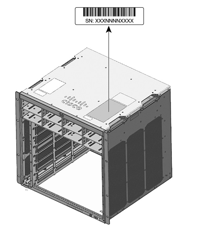
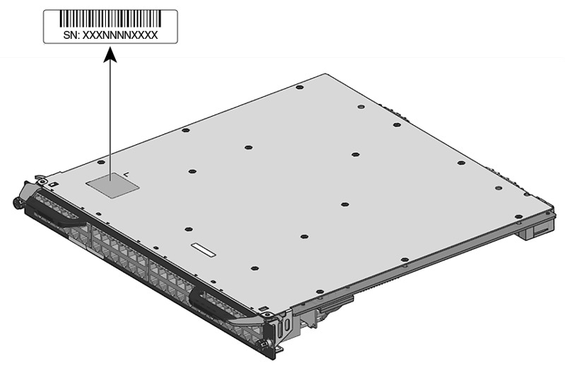
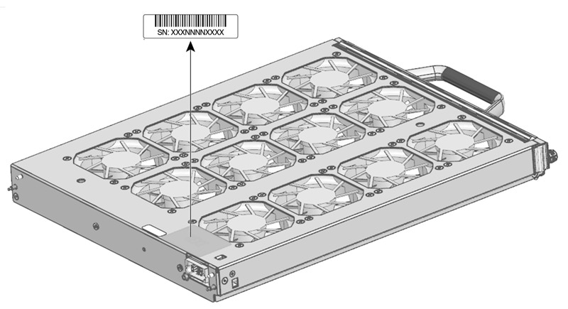
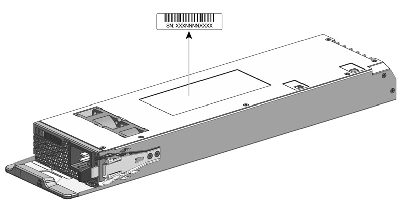
If you contact Cisco Technical Assistance Center (Cisco TAC), you should know the serial number of the part you are having a problem with. The following illustrations show where you can find the serial number on a chassis, supervisor module, line card, power supply module, and fan tray.

You can also use the show version command in privileged EXEC mode, to see the serial number.

Figure 1. Chassis Serial Number Location
Figure 2. Supervisor Module and Line Card Serial Number Location
Figure 3. Fan Tray Serial Number Location
Figure 4. Power Supply Module Serial Number Location

Contacting the Cisco Technical Assistance Center

If you are unable to solve a startup problem after using the troubleshooting suggestions in this chapter, contact a Cisco TAC representative for assistance and further instructions.

Before you call, have the following information ready to help the Cisco TAC assist you as quickly as possible:

  • Date you received the switch

  • Chassis serial number

  • Type of software and release number

  • Maintenance agreement or warranty information

  • Brief description of the problem

  • Console captures related to your problem

  • Brief explanation of the steps you have already taken to isolate and resolve the problem