Installing the Switch

Installation Tasks

These warnings apply to the overall switch installation process:


Warning


Statement 1071—Warning Definition

IMPORTANT SAFETY INSTRUCTIONS

Before you work on any equipment, be aware of the hazards involved with electrical circuitry and be familiar with standard practices for preventing accidents. Read the installation instructions before using, installing, or connecting the system to the power source. Use the statement number at the beginning of each warning statement to locate its translation in the translated safety warnings for this device.

SAVE THESE INSTRUCTIONS


Warning


Statement 1008—Class 1 Laser Product

This product is a Class 1 laser product.


Warning


Statement 1017—Restricted Area

This unit is intended for installation in restricted access areas. Only skilled, instructed, or qualified personnel can access a restricted access area.


Warning


Statement 1024—Ground Conductor

This equipment must be grounded. To reduce the risk of electric shock, never defeat the ground conductor or operate the equipment in the absence of a suitably installed ground conductor. Contact the appropriate electrical inspection authority or an electrician if you are uncertain that suitable grounding is available.


Warning


Statement 1028—More Than One Power Supply

This unit might have more than one power supply connection. To reduce risk of electric shock, remove all connections to de-energize the unit.


Warning


Statement 1032—Lifting the Chassis

To prevent personal injury or damage to the chassis, never attempt to lift or tilt the chassis using the handles on modules, such as power supplies, fans, or cards. These types of handles are not designed to support the weight of the unit.


Warning


Statement 9001—Product Disposal

Ultimate disposal of this product should be handled according to all national laws and regulations.


Warning


Statement 1046—Installing or Replacing the Unit

To reduce risk of electric shock, when installing or replacing the unit, the ground connection must always be made first and disconnected last.

If your unit has modules, secure them with the provided screws.


Warning


Statement 1051—Laser Radiation

Invisible laser radiation may be emitted from disconnected fibers or connectors. Do not stare into beams or view directly with optical instruments.


Warning


Statement 1074—Comply with Local and National Electrical Codes

To reduce risk of electric shock or fire, installation of the equipment must comply with local and national electrical codes.


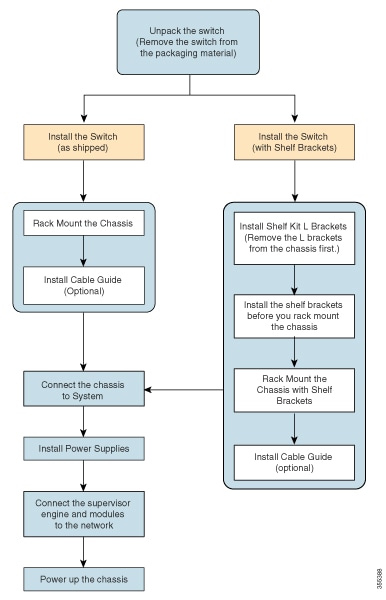
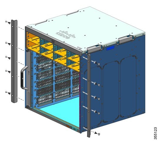
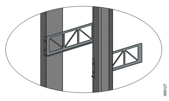
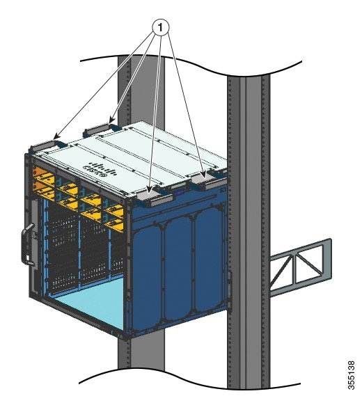
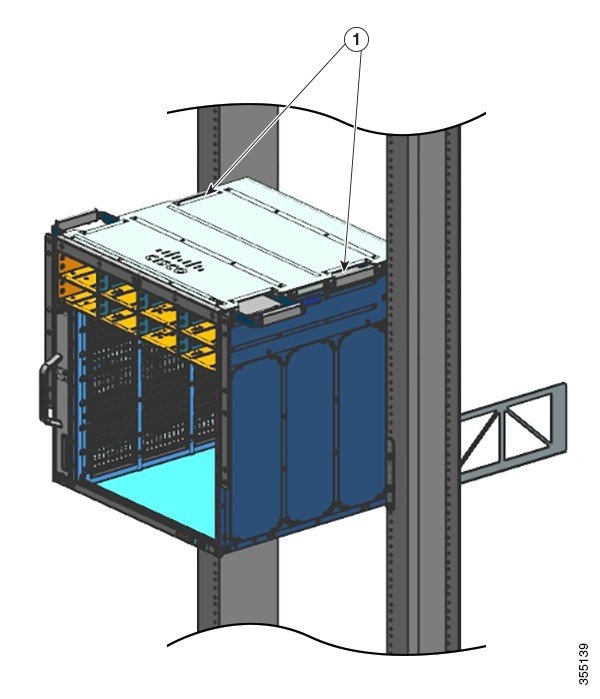
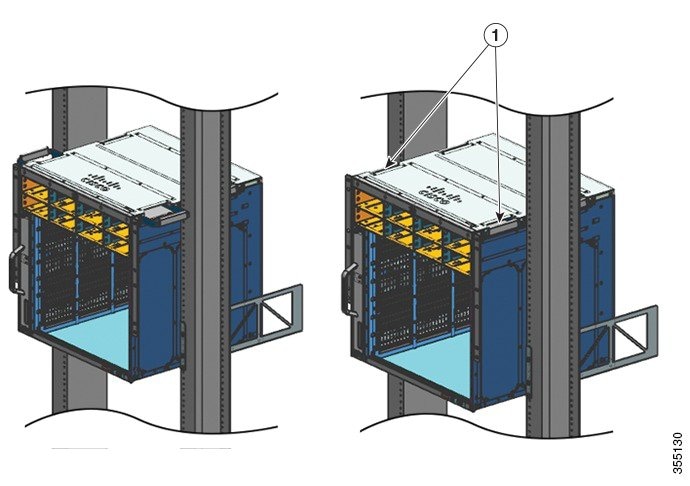
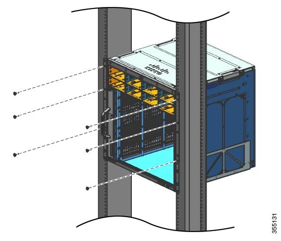
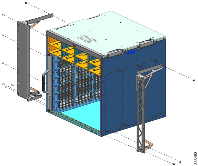
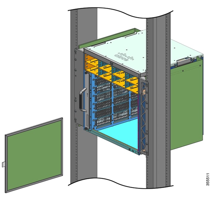
The process of installing the switch can be broken down into a series of tasks as shown in the following figure:


Note


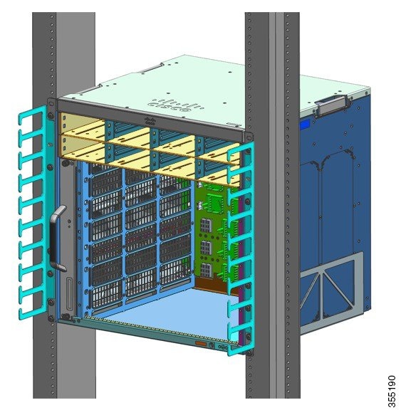
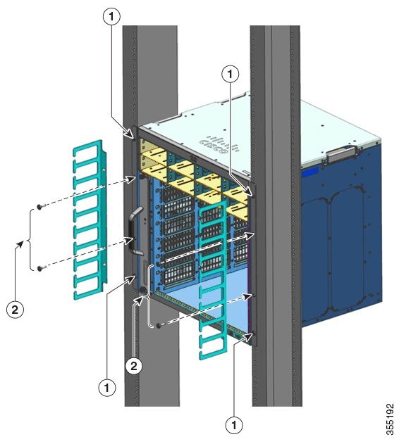
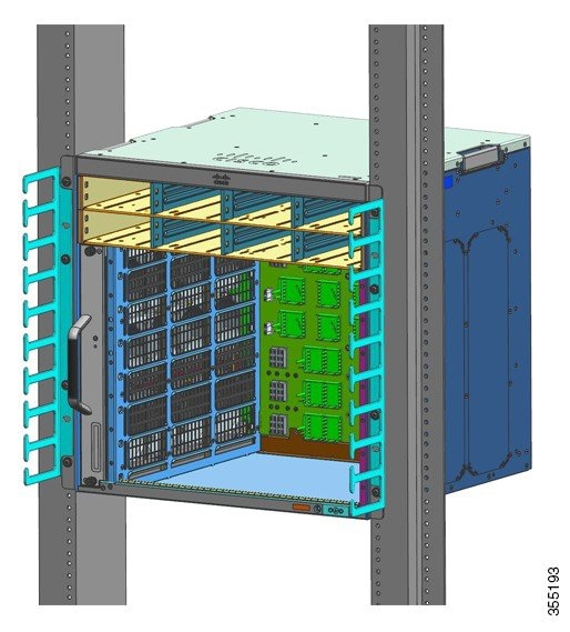
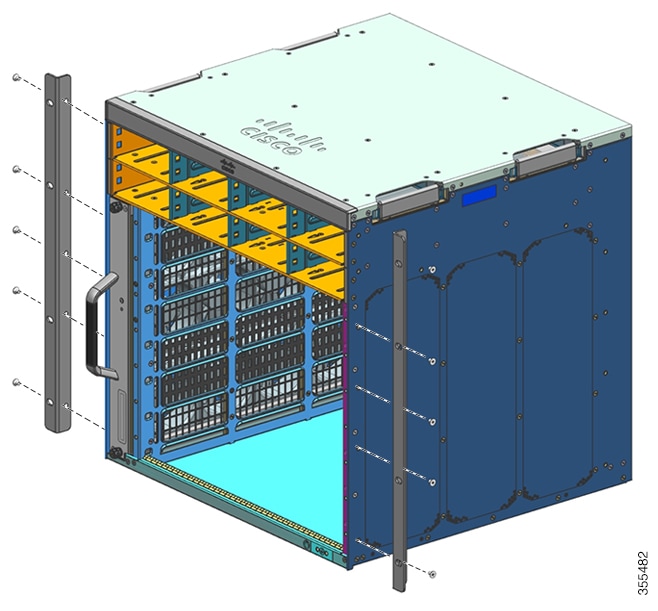
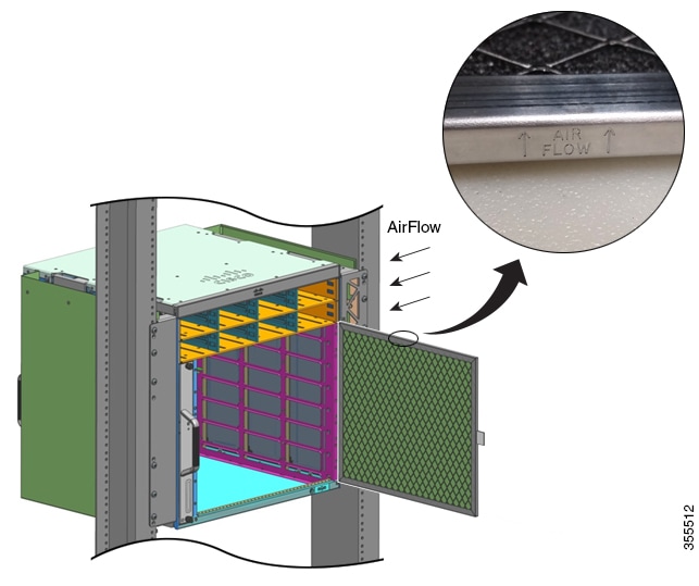
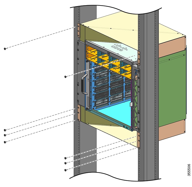
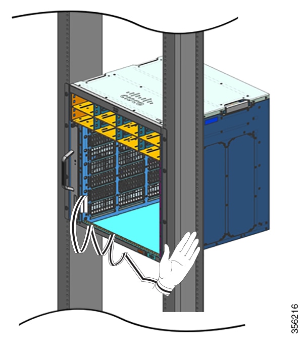
This section illustrates the installation of a Catalyst 9407R Switch switch. All Cisco Catalyst 9400 Series Switches are installed in the equipment rack, the same way.

Further, the equipment racks shown below are for instructional purposes only. For proper operation, ensure that the racks you use comply with site requirements and air flow requirements as stated in the Preparing for Installation section of this document.


Figure 1. Installation Tasks

Unpacking the Switch

Check the contents of the shipping container:

Procedure


Step 1

Check the contents of the accessory kit. Verify that you have received all the listed equipment, including any optional equipment you may have ordered, such as, network interface cables, transceivers, or special connectors.

Step 2

Check the modules in each slot. Ensure that the configuration matches the packing list and that all of the specified interfaces are included.

Step 3

Store the shipping carton.

Tip


Do not discard the shipping container when you unpack the switch. Flatten the shipping cartons and store them with the pallet. You will require these containers if you have to move or ship the switch in the future.


Install the Switch as Shipped

Rack-Mounting the Chassis as Shipped

This procedure shows how to rack mount the chassis as shipped.

Before you begin


Warning


Statement 1006—Chassis Warning for Rack-Mounting and Servicing

To prevent bodily injury when mounting or servicing this unit in a rack, you must take special precautions to ensure that the system remains stable. The following guidelines are provided to ensure your safety:

  • This unit should be mounted at the bottom of the rack if it is the only unit in the rack.

  • When mounting this unit in a partially filled rack, load the rack from the bottom to the top with the heaviest component at the bottom of the rack.

  • If the rack is provided with stabilizing devices, install the stabilizers before mounting or servicing the unit in the rack.


Cable guide installation options have been described in a separate topic. If you are installing the cable guide, read this procedure and the cable guide installation procedure, before you start.

Procedure


Step 1

Insert the rear of the chassis between the mounting posts of the rack.

Step 2

Align the mounting holes in the L bracket on the switch with the mounting holes in the equipment rack.

Figure 2. Securing the Chassis to the Rack Posts

Step 3

Secure the chassis to the rack with either 10-32 or 12-24 pan head screws from the chassis standard accessory kit.

Figure 3. Chassis Secured to the Rack Posts

Step 4

4. Use a tape measure and level to ensure that the chassis is installed straight and level..


What to do next

After installing the chassis in its location, complete the installation process by:

  1. Connecting the chassis to system ground.

  2. Installing and connecting the power supplies to the power source.

  3. Connecting the network interface cables to the supervisor module and line card modules. This may involve installing transceivers before you attach the network interface cables.

  4. Powering up the chassis and verifying the installation.

Install the Switch with Shelf Brackets

Shelf Kit Contents


Note


The shelf kit is not part of the standard accessory kit. You must order it separately by using the chassis-specific part number.

Switch Model

Shelf Kit Part Number

Catalyst 9404R Switch

C9404-SHELF-KIT=

Catalyst 9407R Switch

C9407-SHELF-KIT=

Catalyst 9410R Switch

C9410-SHELF-KIT=

The following table lists the contents of the shelf kit:

Table 1. Shelf Kit Contents

Item and Description

Quantity

(C9404-SHELF-KIT=)

Quantity

(C9407-SHELF-KIT=)

Quantity

(C9410-SHELF-KIT=)

Left L bracket.

Fabricated metal chassis L bracket, to secure the chassis to the rack enclosure.

1

1

1

Right L bracket.

Fabricated metal chassis L bracket, to secure the chassis to the rack enclosure

1

1

1

Shelf brackets

Fabricated metal, rack shelf brackets, to support the weight of the chassis.

2

2

2

12-24 x 0.75-inch Phillips screws

6

6

6

10-32 x 0.75-inch Phillips screws

6

6

6

M4 x 8 mm Phillips flat head screws

4

8

10

Documentation, pointer card

Provides references to related documentation on cisco.com

1

1

1

Installing the Shelf Kit L Brackets

The switch chassis is shipped with two L brackets installed on the front sides of the chassis. If you are rack-mounting the switch using the Shelf accessory, these L brackets must be removed and replaced with L brackets that are part of the shelf kit

Before you begin

You have ordered and received the shelf kit.

Procedure


Step 1

Remove and discard the L brackets and the ten mounting screws that the chassis is shipped with. Do not re-use them during any part of the installation process.

Figure 4. L Brackets the Chassis is Shipped With

1

L Brackets that the chassis is shipped with

-

-

Figure 5. Removing L Brackets the Chassis is Shipped With
Figure 6. Chassis Without L brackets

1

Chassis without L brackets

-

-

Step 2

Remove the L brackets from the shelf kit packaging.

Step 3

Using the M4 x 8 mm Phillips flat head screws in the shelf kit, secure the L brackets to the front-left and front-right sides of the chassis (four on each side).

Figure 7. Installing Shelf Kit L Brackets

What to do next

Mount the shelf brackets on the rack.

Installing the Shelf Brackets

Install the shelf brackets before you install the chassis in the rack. The shelf brackets attach directly to the rack and help support the weight of the chassis while you secure the L brackets to the rack enclosure.

You have to front-mount the shelf brackets.

Before you begin

Determine the clearance between the insides of the left and right rails of your rack system and install the shelf brackets accordingly. Keep these tools handy:

  • Number 1 and Number 2 Phillips screwdrivers

  • 3/16-inch flat-blade screwdriver

  • Tape measure and level

Procedure


Step 1

Position the support flange of the left shelf bracket on the front of the left rail. Align and secure the bracket to the rack by using three screws. Use either 10-32 or 12-24 pan head screws from the shelf kit.

Step 2

Position the support flange of the right shelf bracket on the front of the right rail — make sure that it is level with the left shelf bracket. Align and secure the bracket to the rack by using three screws.

Use the same type of screws for the left and right shelf bracket.

Figure 8. Installing the Shelf Brackets

1

Shelf brackets

2

Pan head screws from the shelf kit that secure the shelf brackets to the rack posts


The shelf brackets are now securely mounted to the rack posts

What to do next

Rack-mount the chassis. Two people will be required for this task.

Rack-Mounting the Chassis

This procedure shows how to rack mount the chassis with shelf brackets.


Warning


Statement 1098—Lifting Requirement

Two people are required to lift the heavy parts of the product. To prevent injury, keep your back straight and lift with your legs, not your back.


Tip


We recommend that you have a third person to assist in this procedure.

To install the switch chassis in the equipment rack, perform these steps:

Before you begin


Warning


Statement 1006—Chassis Warning for Rack-Mounting and Servicing

To prevent bodily injury when mounting or servicing this unit in a rack, you must take special precautions to ensure that the system remains stable. The following guidelines are provided to ensure your safety:

  • This unit should be mounted at the bottom of the rack if it is the only unit in the rack.

  • When mounting this unit in a partially filled rack, load the rack from the bottom to the top with the heaviest component at the bottom of the rack.

  • If the rack is provided with stabilizing devices, install the stabilizers before mounting or servicing the unit in the rack.


  • Install the shelf kit L brackets on the chassis and the shelf brackets on the rack posts.

  • Cable guide installation options have been described in a separate topic. If you are installing the cable guide, read this procedure and the cable guide installation procedure, before you start.

Procedure


Step 1

Pull out all four of the handholds

Figure 9. Chassis handholds

1

All four of the chassis handholds pulled out and the back end of the chassis resting on the edges of the shelf bracket rails.

-

-

Step 2

With a person standing at each side of the chassis, insert one hand into each handhold. Slowly lift the chassis. Avoid sudden twists or moves to prevent injury.

Step 3

Rest the back end of the chassis on the edges of the shelf bracket rails and slide it in until the first pair of handles on both sides of the chassis are near the rack posts.

Step 4

Push in the handholds that are closest to the rack posts

Figure 10. Sliding the Chassis in - Part 1

1

Handholds closest to the rack posts, pushed in.

-

-

Step 5

Continue sliding the chassis in until the second pair of handholds are near the rack posts

Figure 11. Sliding the Chassis in - Part 2

1

Chassis is slid in until the second pair of handholds are near the rack posts.

-

-

Step 6

Push in the the second pair of handholds and continue sliding the chassis in until the L brackets make contact with the rack posts.

Step 7

Secure the chassis to the rack with either the 10-32 or 12-24 pan head screws from the chassis standard accessory kit.

Figure 12. Securing the Chassis to the Rack Posts

Figure 13. Chassis Secured to the Rack Posts

What to do next

After installing the chassis in its location, complete the installation process by:

  1. Connecting the chassis to system ground.

  2. Installing and connecting the power supplies to the power source.

  3. Connecting the network interface cables to the supervisor module and line card modules. This may involve installing transceivers before you attach the network interface cables.

  4. Powering up the chassis and verifying the installation.

Installing the Cable Guide

You can install cable guides with or without the shelf brackets. Follow the corresponding procedure:


Note


Cable guides are part of the standard accessory kit.


Note


You can install cable guides in a NEBS-Compliant set up as well.


Installing the Cable Guide With Shelf Brackets

Procedure


Step 1

Mount the shelf brackets with only two screws on each side

Step 2

Using only one screw on each side, secure the L bracket to the rack rails.

Step 3

Position the cable guides and align with the L brackets and shelf brackets.

Using one screw on each side, align the cable guide mounting holes with the shelf bracket holes and the rack rail holes,

Using two screws on each side, align the cable guide mounting holes with the L bracket holes and the rack rail holes.

1

Screws that are mounted before the cable guide is—two on each side for the shelf bracket and one on each side for the L bracket.

2

Remaining screws that are mounted when installing the cable guide—one on each side for the shelf bracket and two on each side for the L bracket.


Cable guide installation with shelf brackets is complete.

Installing the Cable Guide Without Shelf Brackets

Procedure


Step 1

Secure the chassis to the rack rails with only two screws on each side.

Step 2

Position the cable guides and align with the L brackets.

1

Screws that are mounted before the cable guide is—two on each side, securing the L bracket to the rack rails.

2

Remaining screws that are mounted when installing the cable guide—two on each side, aligning and securing the cable guide and L bracket to the rack rails.


Cable guide installation without shelf brackets is complete.

Install the Switch in a NEBS-Compliant Mode

NEBS-Compliant Air Filter

A Network Equipment-Building System (NEBS) compliant installation allows filtered, front-to-rear airflow. To mount the chassis in a NEBS-compliant mode with the air filter, use a 23-inch rack mount. Filter brackets that are mounted on the side of the chassis hold the air filter. For more details on the air filter, refer step 6 of Rack-Mounting the Chassis in a NEBS-Compliant Mode section.


Note


In order to meet GR-63-CORE requirements, the switch must be installed in a NEBS-Compliant Mode.


A 23-inch rack mount is used for mounting the switch in a standard 23 inch (58.4 cm) equipment rack with two unobstructed outer posts. This kit is not suitable for racks with obstructions (such as a power strip) that could impair access to the field-replaceable units (FRUs) of the switch.

Table 2. 23 Inch Rack Mount Kit Part Numbers

Switch Model

23-Inch Rack Mount Kit Part Number

Catalyst 9404R Switch

C9404-FB-23-KIT=

Catalyst 9407R Switch

C9407-FB-23-KIT=

Catalyst 9410R Switch

C9410-FB-23-KIT=

Table 3. 23 Inch Rack Mount Kit Contents

Quantity

Parts Description

2

Rack Mounts

6

M4 Phillips pan-head screws

6

12-24 x 3/4-inch Phillips binder-head screws

Rack-Mounting the Chassis in a NEBS-Compliant Mode


Warning


Statement 1006—Chassis Warning for Rack-Mounting and Servicing

To prevent bodily injury when mounting or servicing this unit in a rack, you must take special precautions to ensure that the system remains stable. The following guidelines are provided to ensure your safety:

  • This unit should be mounted at the bottom of the rack if it is the only unit in the rack.

  • When mounting this unit in a partially filled rack, load the rack from the bottom to the top with the heaviest component at the bottom of the rack.

  • If the rack is provided with stabilizing devices, install the stabilizers before mounting or servicing the unit in the rack.


Before you begin

Prepare for the installation as follows:

  • Place the chassis on the floor or on a sturdy table as close as possible to the rack. Leave enough clearance to allow you to move around the chassis.

  • Open the rack-mount kit and verify that all parts are included.


Note


Some equipment racks provide a power strip along the length of one of the rear posts. If your rack has this feature, consider the position of the strip when planning fastener points. Before installing the brackets on the chassis, determine whether to install the chassis from the front or the rear of the rack.


Procedure


Step 1

Remove and discard the mounting ears and the ten mounting screws of the chassis. Do not reuse them during any part of the installation process.

Figure 14. Remove the Mounting Ears

Step 2

Install the rack ear brackets on the left and right sides of the chassis. These brackets connect the chassis to the rack.

Figure 15. Install the Rack Ear Brackets

Step 3

Install the filter brackets.

Figure 16. Install the Filter Brackets

Step 4

Install the Right and Left Wall covers.

Figure 17. Install the Wall Covers

Step 5

Secure the chassis to the rack with either 10-32 or 12-24 pan head screws from the chassis standard accessory kit.

Figure 18. Secure the Chassis to Rack

Step 6

Slide the air filter into the air filter slot.

Note


The arrows on the top edge of the air filter note the direction of airflow. (Airflow direction is from right to left, when you stand facing the chassis). Insert the air filter into its housing with the arrows pointing toward the chassis.

Figure 19. NEBS-Compliant Air Filter

Note


We recommend that you change the air filter every 3 months. However, examine the air filter once a month (or more often in dusty environments) and replace it if it appears to be excessively dirty or damaged. To comply with Telecordia GR-63-Core standard air filter requirements for NEBS deployments, the air filter must be replaced, not cleaned.

Step 7

Install the top and base covers as shown in illustrations:

Figure 20. Top Cover and Base Cover

What to do next

After installing the chassis in a NEBS-Compliant mode, complete the installation process by:

  1. Connecting the chassis to system ground.

  2. Installing and connecting the power supplies to the power source.

  3. Connecting the network interface cables to the supervisor module and line card modules. This may involve installing transceivers before you attach the network interface cables.

  4. Powering up the chassis and verifying the installation.

  5. Turning on the NEBS mode for the fan tray. See Useful Cisco IOS Commands - Fan Tray Assembly

Establishing System Ground

To attach the grounding lug and cable to the grounding pad, perform these steps:

Before you begin


Warning


Statement 1003—DC Power Disconnection

To reduce risk of electric shock or personal injury, disconnect DC power before removing or replacing components or performing upgrades.


Warning


Statement 1046—Installing or Replacing the Unit

To reduce risk of electric shock, when installing or replacing the unit, the ground connection must always be made first and disconnected last.

If your unit has modules, secure them with the provided screws.


To connect the system ground, you require the following tools and materials:

  • Grounding lug—A two-hole grounding lug, which supports a 6 AWG size wire. Supplied as part of the standard accessory kit.

  • Grounding screws—Two M4 x 8 mm (metric) pan-head screws. Supplied as part of the standard accessory kit.

  • Grounding wire—The grounding wire should be sized according to local and national installation requirements. A 6 AWG copper conductor is required for U.S. installations. Commercially available 6 AWG wire is recommended. The length of the grounding wire depends on the proximity of the switch to proper grounding facilities.

  • No. 1 Phillips screwdriver.

  • Crimping tool to crimp the grounding wire to the grounding lug.

  • Wire-stripping tool to remove the insulation from the grounding wire.

Procedure


Step 1

Use a wire-stripping tool to remove approximately 0.75 inches (19 mm) of the covering from the end of the grounding wire.

Step 2

Insert the stripped end of the grounding wire into the open end of the grounding lug.

Step 3

Crimp the grounding wire in the barrel of the grounding lug. Verify that the ground wire is securely attached to the ground lug.

Step 4

Secure the grounding lug to the system ground connector with two M4 screws. Ensure that the grounding lug and the grounding wire do not interfere with other switch hardware or rack equipment.

Figure 21. Locating and Connecting System Ground

1

Stripped end of the grounding wire inserted into the open end of the grounding lug

3

M4 screws to secure the lug to the connector

2

Grounding lug

4

System ground location

Figure 22. System Ground Connected

Step 5

Prepare the other end of the grounding wire, and connect it to an appropriate grounding point in your site to ensure adequate earth ground for the switch.


Attaching an ESD Strap

After you install the system ground lug, follow these steps to correctly attach the electrostatic discharge (ESD) wrist strap that is provided with the standard accessory kit and all FRUs:

Before you begin

  • Do not use the wrist strap if it is wet.

  • Do not use the wrist strap on equipment with operating voltage exceeding 250V.

  • Ensure that you are not grounded by any other means than through the wrist strap while servicing.

Procedure


Step 1

Open the wrist strap package, unwrap and locate the two ends of the ESD strap.

One end of the strap terminates with the black metal strap exposed; this is wrist end. The other end terminates with a patch of copper foil; this is the equipment end.

1

Wrist end of the ESD wrist strap.

2

Equipment end of the ESD wrist strap

Step 2

On the wrist end of the strip, locate the length of conductive film. Wrap the adhesive side around your wrist such that it touches bare skin well.

Step 3

Peel off the adhesive from the equipment end and attach it to an unpainted metal surface of the equipment you are servicing.

When handling modules, follow these guidelines:

  • Handle carriers using the available handles or edges only; avoid touching the printed circuit boards or connectors.

  • Place a removed component boardside up on an antistatic surface or in a static shielding container. If you plan to return the component to the factory, immediately place it in a static shielding container.

  • Never attempt to remove the printed circuit board from the metal carrier.

    Caution


    For safety, periodically check the resistance value of the antistatic strap. The measurement should be between 1 and 10 megohm (Mohm).


Verifying the Switch Chassis Installation

To verify the switch chassis installation, perform these steps:

Procedure


Step 1

Verify that the ejector levers of each module are fully closed (parallel to the faceplate) to ensure that the supervisor and all the line cards are fully seated in the backplane connectors.

Step 2

Check the captive installation screws of each module, and tighten any loose captive installation screws.

Step 3

Verify that all empty module slots and power supply bays have blanks installed properly. The blanks optimize the air flow through the chassis and contain EMI.

Warning


Statement 1029—Blank Faceplates and Cover Panels

Blank faceplates and cover panels serve three important functions: they reduce the risk of electric shock and fire, they contain electromagnetic interference (EMI) that might disrupt other equipment, and they direct the flow of cooling air through the chassis. Do not operate the system unless all cards, faceplates, front covers, and rear covers are in place.

Step 4

Turn on the power supply switches to power up the system. During the power-up sequence, the system performs a series of bootup diagnostic tests.

Note


The switch is designed to boot up in less than 30 minutes, provided that the neighboring devices are in fully operational state.


What to do next

In case of a problem with any of the hardware components, refer to the Troubleshooting section.

Additional system diagnostic tests are also available. These tests allow you to perform a complete sanity check on the system prior to inserting the system into your network and to monitor the health of the system while the system is running.


Tip


When prestaging systems in a nonproduction environment, we recommend that you run all the diagnostic tests, including the disruptive tests, to prescreen the systems for failures, if any.