Removing and Installing a Fan Tray
Online Insertion and Removal
While the fan tray is designed to be removed and installed while the system is operating (powered on) and without presenting an electrical hazard or damage to the system, there is a time constraint when you remove and replace the fan tray in a system that is powered on.
 Caution |
If the service mode is not enabled, the system can safely run without a fan tray only for two minutes, until critical temperature threshold is exceeded. Watch for any alarms triggered in software. After the critical temperature threshold is exceeded, without sufficient cooling, the system shuts down if the alarm is not cleared. |
When the fan tray is removed and replaced in a non operating system, there is no time constraint.
Following the Correct Removal and Replacement Procedure
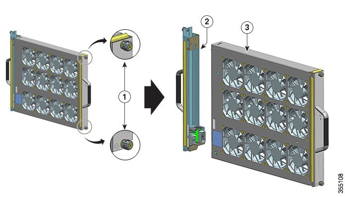
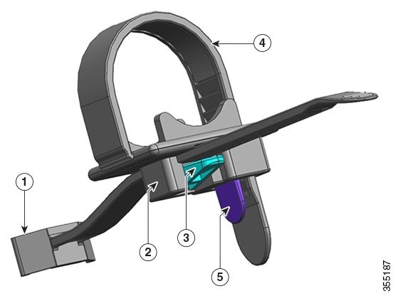
When you order the fan tray or a spare, the entire fan tray assembly is shipped. The fan tray assembly consists of the fan tray and an adapter that is attached to the fan tray.
You can remove and replace the fan tray from the front or the rear. When removed from the front of the chassis, only the fan tray is removed. When removed from the rear, the entire fan tray assembly (including the adapter) is removed. Accordingly, you must detach the adapter from the spare fan tray assembly when installing or replacing the fan tray from the front; you must install the entire fan tray assembly when installing the spare from the rear.
Removal and replacement from the front is suited to situations where access to the rear of the system is restricted. For instance, where the installation is in a closet.
Removal and replacement from the rear is suited to situations where input and output cables are routed across the front panel, limiting access to the front panel of the fan tray.
Follow the corresponding removal and replacement procedures.
Enabling the Service Mode Before Removing a Fan Tray
 Warning |
Statement 1073—No User-Serviceable Parts There are no serviceable parts inside. To avoid risk of electric shock, do not open. |
Enabling the service mode is a precautionary step that we recommend you complete, before you remove a fan tray from the chassis. In the service mode, the system pushes the fans to operate at full speed for 10 minutes, allowing the system to cool down sufficiently and sustain temperatures for the duration of servicing. The system automatically turns off (self-terminates) the service mode after 10 minutes.
 Important |
Proceed with removing and replacing the fan tray immediately after the service mode self-terminates. |
-
If the service mode is not enabled before servicing, only two minutes of fan-less operation can be safely assured in a normal environment.
-
If the service mode is enabled prior to servicing, four minutes of fan-less operation can be assured for all normal operating conditions, at full traffic load, in any configuration.
In a system that is operational, enabling the service mode applies to removal or replacement procedures from the front and the rear.
You do not have to enable this mode if you are removing and replacing the fan tray in a system that is not powered on. The service mode is also not required if the fan tray is being replaced for having two or more bad individual fans, because the fan tray will already be running at full speed.
To enable the service mode, enter the test platform hardware chassis fantray service-mode on command in the privileged EXEC mode. For example:
Device# test platform hardware chassis fantray service-mode on
fantray service mode on
To turn off the service mode before the system-allotted 10-minute duration, enter the test platform hardware chassis fantray service-mode off command in the privileged EXEC mode.
Removing a Fan Tray from the Front
When you remove a fan tray from the front, only the fan tray is removed, excluding the adapter. To remove a fan tray from the front, follow the steps described here.
Caution |
When removing the fan tray, keep your hands and fingers away from the spinning fan blades. Let the fan blades completely stop before you remove the fan tray. |
Warning |
Statement 1073—No User-Serviceable Parts There are no serviceable parts inside. To avoid risk of electric shock, do not open. |
Warning |
Statement 1074—Comply with Local and National Electrical Codes To reduce risk of electric shock or fire, installation of the equipment must comply with local and national electrical codes. |
Before you begin
You may need a Phillips-head screwdriver to loosen the captive installation screws.
Procedure
|
Step 1 |
Ready the replacement fan tray.
|
||||||||||
|
Step 2 |
Enable the service mode In a system that is powered on, enabling the service mode for the system-allotted 10 minutes safely assures fan-less operation for four minutes. See Enabling the Service Mode Before Removing a Fan Tray.
|
||||||||||
|
Step 3 |
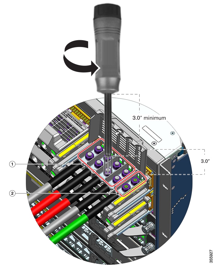
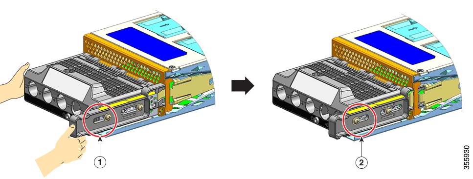
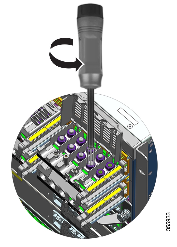
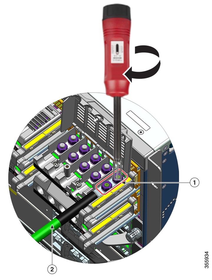
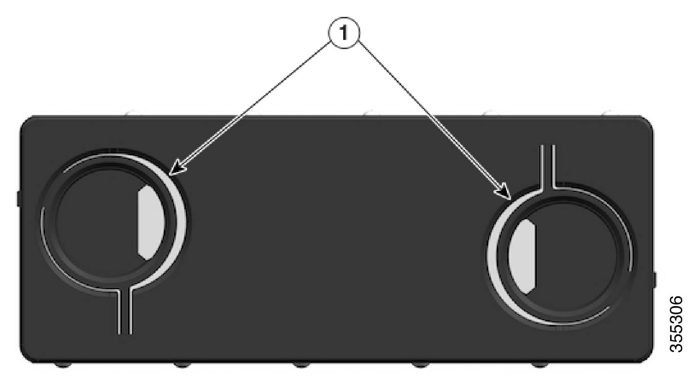
Remove the fan tray from the chassis - loosen the two captive installation screws on the front panel of the fan tray (the side with the fan STATUS LED). 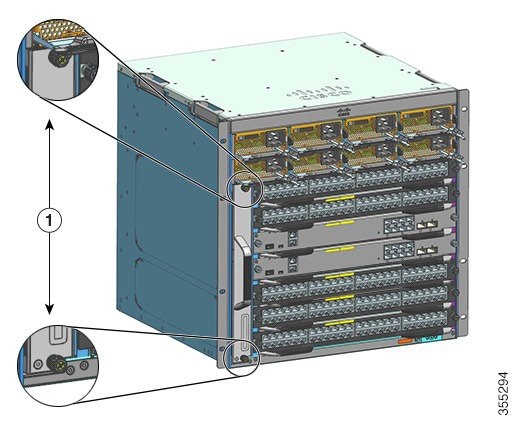
|
||||||||||
|
Step 4 |
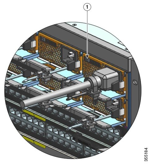
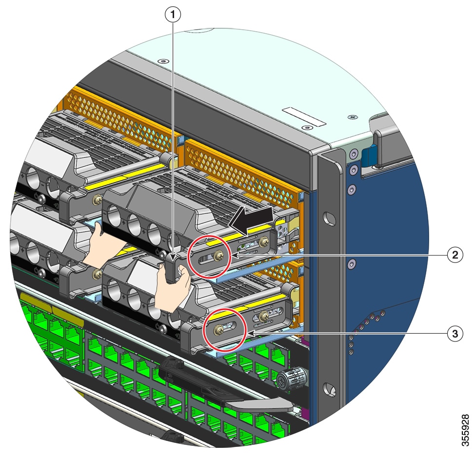
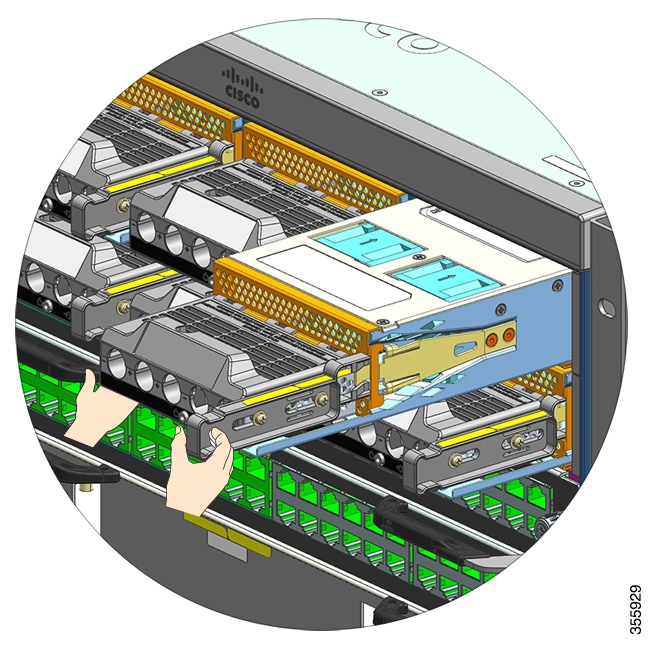
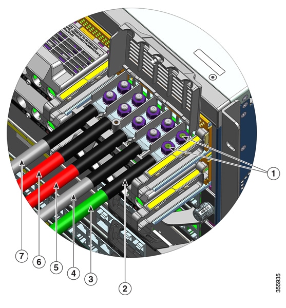
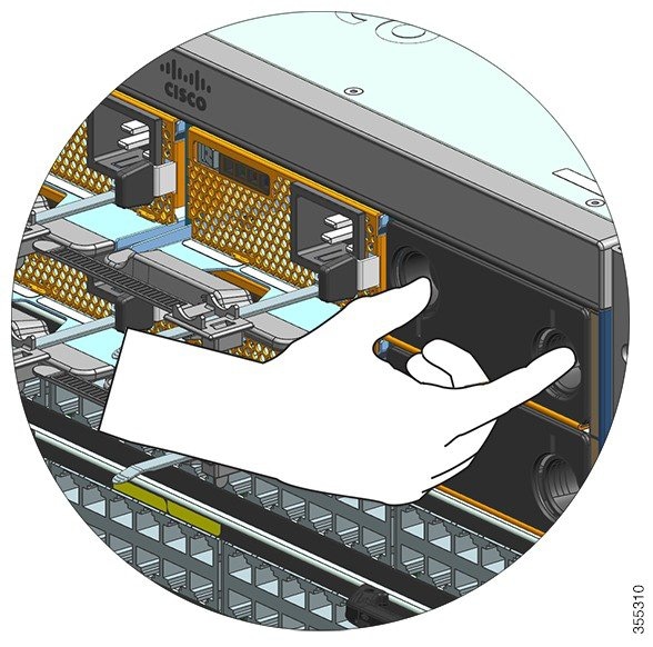
Grasp the fan tray handle and pull it out only partially (0.25 inches), to unmate the connector and unseat it from the backplane. After unmating the connector, allow three seconds to let the fan blades stop spinning completely. When unmating the connector, gently move the fan tray from side to side, if necessary. The fans are equipped with a braking mechanism that fully stop the blades within three seconds of being de-energized (You will not be able to visualy inspect the fan to see whether the blades are spinning or not). |
||||||||||
|
Step 5 |
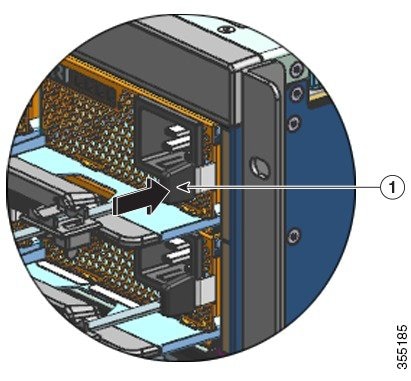
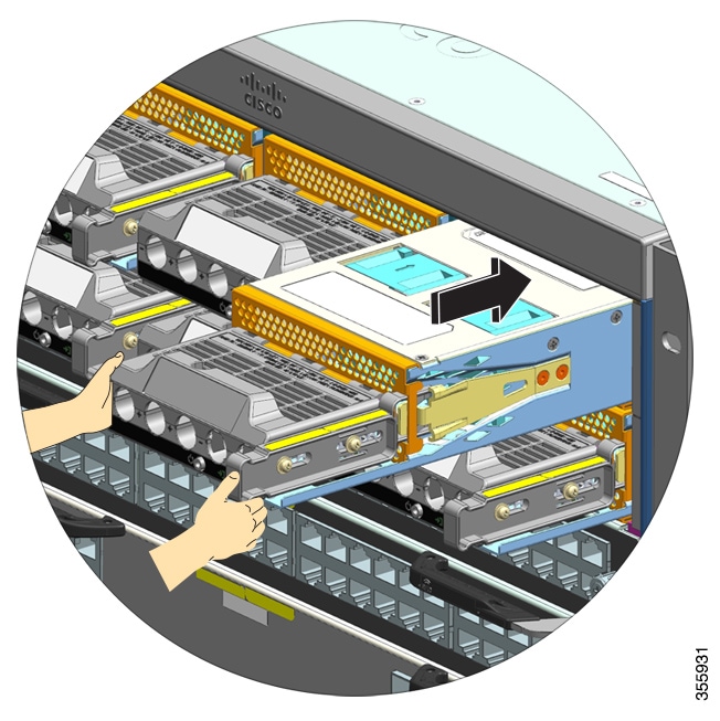
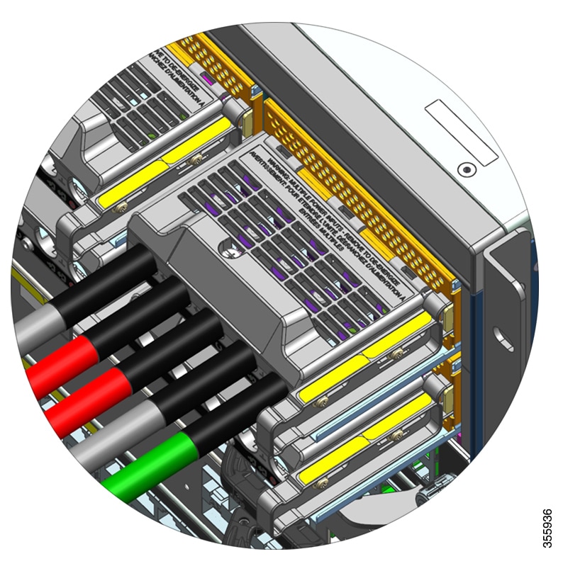
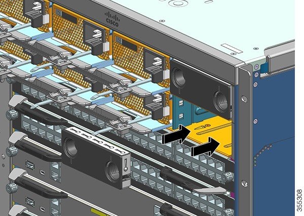
Place your other hand underneath to support the bottom of the fan tray and then slide it out of the bay completely. Only the fan tray is removed from the chassis (excluding the adapter). |
What to do next
Set the removed fan tray aside and immediately proceed with installing the replacement or spare fan tray.
Installing a Fan Tray from the Front
To install a fan tray from the front, follow the steps described here.
Warning |
Statement 1073—No User-Serviceable Parts There are no serviceable parts inside. To avoid risk of electric shock, do not open. |
Warning |
Statement 1074—Comply with Local and National Electrical Codes To reduce risk of electric shock or fire, installation of the equipment must comply with local and national electrical codes. |
Before you begin
Ensure that a replacement fan tray (with the adapter module detatched), is ready for installation. There is a time constraint when you remove and replace a fan tray in a system that is powered on - if you have enabled the service mode prior to servicing, fan-less operation can be safely assured for four minutes only.
You may need a Phillips-head screwdriver to loosen the captive installation screws.
Procedure
|
Step 1 |
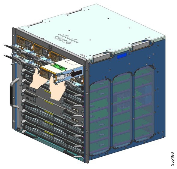
Grasp the front handle with one hand and place your other hand underneath the fan tray to support it. Hold the fan tray with the fans facing to the right. |
||||
|
Step 2 |
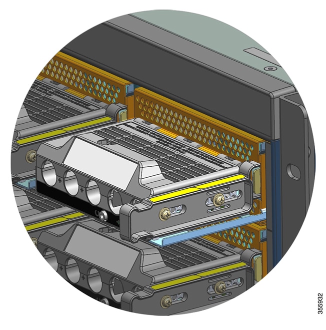
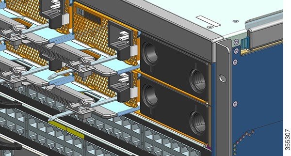
Place the fan tray in the fan tray bay such that it rests on the chassis, and then lift the fan tray up slightly, aligning the top and bottom guides. 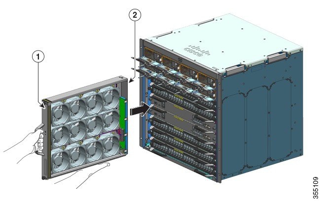
|
||||
|
Step 3 |
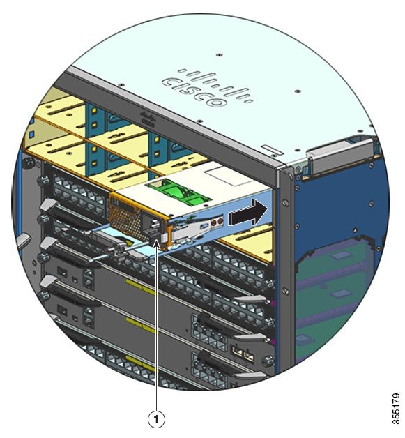
Slide the fan tray into the chassis until the two captive installation screws make contact with the chassis. |
||||
|
Step 4 |
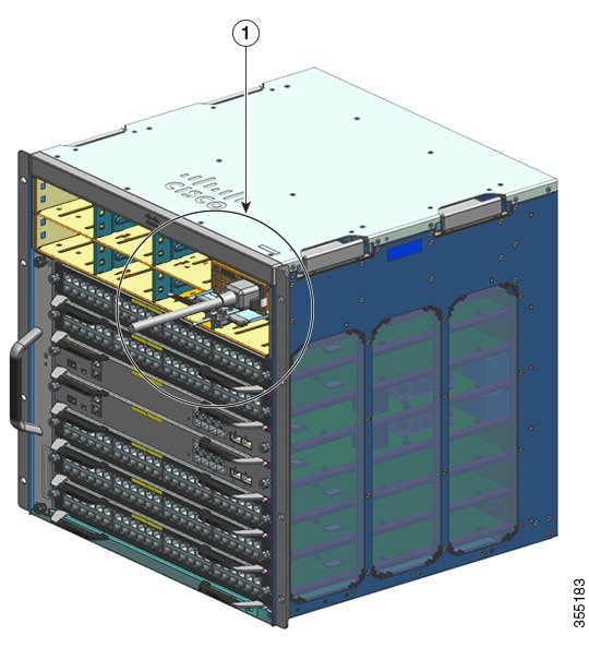
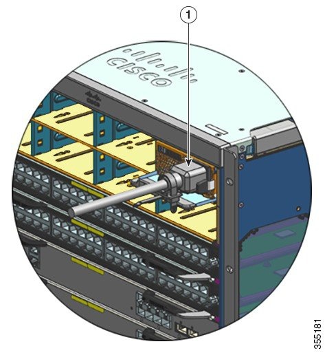
Tighten the two captive installation screws on the front, to secure the fan tray assembly in the chassis. |
||||
|
Step 5 |
Verify that you have installed the fan tray correctly. See Verifying Fan Tray Installation. |
Removing a Fan Tray from the Rear
When you remove a fan tray from the rear, the fan tray assembly is removed. This includes the fan tray and the adapter. To remove a fan tray from the rear, follow the steps described here.
Caution |
When removing the fan tray, keep your hands and fingers away from the spinning fan blades. Let the fan blades completely stop before you remove the fan tray. |
Warning |
Statement 1073—No User-Serviceable Parts There are no serviceable parts inside. To avoid risk of electric shock, do not open. |
Warning |
Statement 1074—Comply with Local and National Electrical Codes To reduce risk of electric shock or fire, installation of the equipment must comply with local and national electrical codes. |
Before you begin
You may need a Phillips-head screwdriver to loosen the captive installation screws.
Procedure
|
Step 1 |
Ready the replacement fan tray by removing it from the shipping packaging. Keep it on an anti-static mat and within arm's reach. Do not detach the adapter module.
|
||||||
|
Step 2 |
Enable the service mode In a system that is powered on, enabling the service mode for the system-allotted 10 minutes safely assures fan-less operation for four minutes. See Enabling the Service Mode Before Removing a Fan Tray.
|
||||||
|
Step 3 |
Remove the fan tray from the chassis - loosen the two captive installation screws on the rear panel of the fan tray. 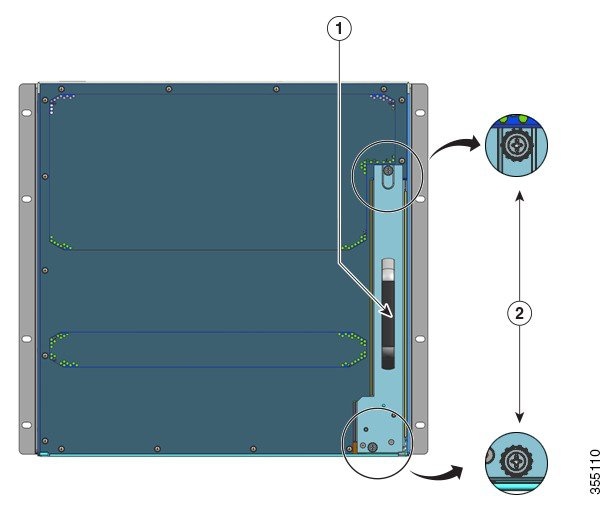
|
||||||
|
Step 4 |
Grasp the fan tray handle and pull it out only partially (0.25 inches), to unmate the connector and unseat it from the backplane. After unmating the connector, allow three seconds to let the fan blades stop spinning completely. When unmating the connector, gently move the fan tray from side to side, if necessary. The fans are equipped with a braking mechanism that fully stop the blades within three seconds of being de-energized (You will not be able to visualy inspect the fan to see whether the blades are spinning or not). |
||||||
|
Step 5 |
Place your other hand underneath to support the bottom of the fan tray and then slide it out of the bay completely. The entire fan tray assembly is removed from the chassis (including the adapter). |
What to do next
Set the removed fan tray aside and immediately proceed with installing the replacement or spare fan tray.
Installing a Fan Tray from the Rear
To install a fan tray from the rear, follow the steps described here.
Warning |
Statement 1073—No User-Serviceable Parts There are no serviceable parts inside. To avoid risk of electric shock, do not open. |
Warning |
Statement 1074—Comply with Local and National Electrical Codes To reduce risk of electric shock or fire, installation of the equipment must comply with local and national electrical codes. |
Before you begin
Ensure that a replacement fan tray assembly (with the adapter module intact), is ready for installation. There is a time constraint when you remove and replace the fan tray in a system that is powered on - if you have enabled the service mode prior to servicing, fan-less operation can be safely assured for four minutes only.
You may need a Phillips-head screwdriver to loosen the captive installation screws.
Procedure
|
Step 1 |
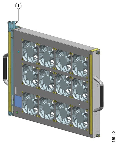
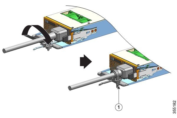
On the replacement fan tray assembly, ensure that the two screws securing the fantray to the adapter (on the side with the fan STATUS LEDs) are tight. Be careful not to overtighten the screws. |
||||
|
Step 2 |
Grasp the rear handle with one hand and place your other hand underneath, to support the botton of the fan try assembly (such that the side with the STATUS LED is inserted first). 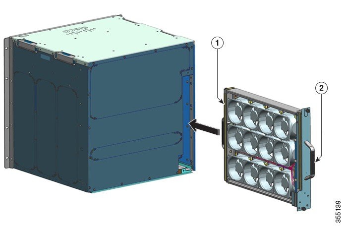
|
||||
|
Step 3 |
Place the fan tray assembly into the fan tray bay so it rests on the chassis. Lift the fan tray up slightly, aligning the top and bottom guides. |
||||
|
Step 4 |
Slide the fan tray assembly into the chassis until the two captive installation screws make contact with the chassis. |
||||
|
Step 5 |
Tighten the two captive installation screws on the rear to secure the fan tray assembly in the chassis. |
||||
|
Step 6 |
Verify that you have installed the fan tray correctly. See Verifying Fan Tray Installation. |
Verifying Fan Tray Installation
To verify that the new fan tray is installed correctly and is operating properly, follow these steps:
Before you begin
To check the operation of the fans, you should have powered up the chassis.
Procedure
|
Step 1 |
Listen for the fans; you should immediately hear them operating. If you do not hear them, ensure
|
||
|
Step 2 |
Check if the fan tray LED is lit and is green. If the LEDs indicate a problem, see the Troubleshooting the Fan Tray Assembly section for help with isolating the problem. |
What to do next
If after several attempts the fans do not operate, or if you experience trouble with the installation (for instance, if the captive installation screws do not align with the chassis holes), contact Cisco Technical Assistance Center (see Cisco Support), for assistance.


 Feedback