- Preface
- Product Overview
- Preparing for Installation
- Installing the Switch
- Installing and Removing Power Supplies
- Installing the Modular Port Card
- Replacing the Fan Tray
- Technical Specifications
- Module Connectors and Cable Specifications
- Repacking the Switch
- Troubleshooting
- Installing the USB Drivers
Module Connectors and Cable Specifications
Module Connectors
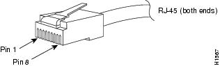
RJ-45 Connector
The RJ-45 connector is used to connect a Category 3, Category 5, Category 5e, or Category 6 foil twisted-pair or unshielded twisted-pair cable from the external network to the module interface connector.
 Caution | Category 5e, Category 6, and Category 6a cables can store large levels of static electricity because of the dielectric properties of the materials used in their construction. Always ground the cables (especially in new cable runs) to a suitable and safe earth ground before connecting them to the module. |
Caution | To comply with GR-1089 intrabuilding and lightning immunity requirements, you must use a foil twisted-pair (FTP) cable that is properly grounded at both ends. |
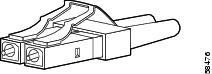
LC Connector
The LC fiber optic connector is a small form-factor fiber-optic connector that provides high-density fiber connectivity. The LC connector can be used with either MMF cable or SMF cable. The LC connector uses a latching clip mechanism that is similar to the one used on the RJ-45 copper connector.
 Warning | Invisible laser radiation may be emitted from disconnected fibers or connectors. Do not stare into beams or view directly with optical instruments. Statement 1051 |
 Note | Make sure that the optical connectors are clean before making the connections. Contaminated connectors can damage the fiber and cause data errors. |
Cables and Adapters
SFP Module Cables
For cabling specifications, refer to the following notes:
Each port must match the wave-length specifications on the other end of the cable, and the cable must not exceed the stipulated cable length. Copper 1000BASE-T SFP module transceivers use standard four twisted-pair, Category 5 cable at lengths up to 328 feet (100 meters).
Cable Pinouts
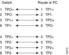
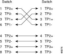
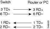
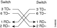
Identifying a Crossover Cable
Console Port Adapter Pinouts
The RS-232 console port uses an 8-pin RJ-45 connector. Use an RJ-45-to-DB-9 adapter cable to connect the switch console port to a console PC. You need to provide a RJ-45-to-DB-25 female DTE adapter to connect the switch console port to a terminal.
Console Port Mode 2 Signaling and Pinouts
This section provides the signaling and pinouts for the console port in mode 2. (The port mode switch in the out position.)
| Console Port | Console Device |
|---|---|
|
Pin (signal) |
Input/Output |
|
1 (RTS)1 |
Output |
|
2 (DTR) |
Output |
|
3 (RxD) |
Input |
|
4 (GND) |
GND |
|
5 (GND) |
GND |
|
6 (TxD) |
Output |
|
7 (DSR) |
Input |
|
8 (CTS)2 |
Input |
Cleaning the Fiber-Optic Connectors
Fiber-optic connectors are used to connect two fibers together. When these connectors are used in a communications system, proper connection becomes a critical factor.
Fiber-optic cable connectors can be damaged by improper cleaning and connection procedures. Dirty or damaged fiber-optic connectors can result in communication that is not repeatable or is inaccurate.
Fiber-optic connectors differ from electrical or microwave connectors. In a fiber-optic system, light is transmitted through an extremely small fiber core. Because fiber cores are often 62.5 microns or less in diameter, and dust particles range from a tenth of a micron to several microns in diameter, dust and any contamination at the end of the fiber core can degrade the performance of the connector interface where the two cores meet. The connector must be precisely aligned, and the connector interface must be absolutely free of trapped foreign material.
Connector loss or insertion loss is a critical performance characteristic of a fiber-optic connector. Return loss is also an important factor. Return loss specifies the amount of reflected light; the lower the reflection, the better the connection. The best physical-contact connectors have return losses greater than -40 dB, although -20 to -30 dB is more common.
The connection quality depends on two factors: the type of connector and the proper cleaning and connection techniques. Dirty fiber connectors are a common source of light loss. Keep the connectors clean at all times, and keep the dust covers installed when the connectors are not in use.
Before installing any type of cable or connector, use a lint-free alcohol pad from a cleaning kit to clean the ferrule, the protective white tube around the fiber, and the end-face surface of the fiber.
As a general rule, whenever there is a significant, unexplained loss of light, clean the connectors.
Guidelines
Connectors that are used inside the system are cleaned by the manufacturer and connected to the adapters in a proper manner. The operation of the system will be error free if the customer provides clean connectors on the application side and follows these guidelines:
-
Does not clean the inside of the connector adapters.
-
Does not use force or quick movements when connecting the fiber-optic connectors in the adapters.
-
Covers the connectors and adapters to keep the inside of the adapters or the surface of the connectors from getting dirty when not using the connectors or while cleaning the chassis.
How to Clean the Fiber-Optic Connectors
Caution | Use extreme care when removing or installing connectors so that you do not damage the connector housing or scratch the end-face surface of the fiber. Always install protective covers on unused or disconnected components to prevent contamination. Always clean fiber connectors before installing them. |
Warning | Invisible laser radiation may be emitted from disconnected fibers or connectors. Do not stare into beams or view directly with optical instruments. Statement 1051 |
 Feedback