- Preface
- Product Overview
- Preparing for Installation
- Installing the Switch
- Installing and Removing Power Supplies
- Installing the Modular Port Card
- Replacing the Fan Tray
- Technical Specifications
- Module Connectors and Cable Specifications
- Repacking the Switch
- Troubleshooting
- Installing the USB Drivers
Product
Overview
The Catalyst 6880-X switch is an extensible fixed-aggregation switch supporting redundant power supplies and slots for up to four optional port card modules. The chassis has 16 fixed 10-Gigabit SFP+, 1-Gigabit SFP, or 100BASE-FX SFP ports. Each system can be built up to 80 ports in 16-port increments.
Switch Models
|
Switch Model |
Description |
|---|---|
|
Catalyst 6880-X-LE |
16 10-Gigabit SFP+, 1-Gigabit SFP, or 100BASE-FX SFP ports, four port card slots, two power supply slots. It supports standard FIB, ACL, and NetFlow tables. |
|
Catalyst 6880-X |
16 10-Gigabit SFP+, 1-Gigabit SFP, or 100BASE-FX SFP ports, four port card slots, two power supply slots. It supports larger FIB, ACL, and NetFlow tables. |
Front Panel Components
This section describes the front panel components:
-
16 SFP+ ports or 100BASE-FX fiber-optic SFP ports
-
Half-wide modular slots
-
Power supply slots
-
Management port
-
USB ports
-
Console port
-
System reset button
-
LEDs
-
Fan tray

|
1 |
16 SFP+ ports or 100BaseFX fiber-optic ports |
8 |
System ID (blue beacon LED) |
|
2 |
Four half-wide port card modular slots 1 |
9 |
USB port (console port con0) |
|
3 |
Two power supply slots 2 |
10 |
USB LED |
|
4 |
Management port (mgmt0) |
11 |
Status LED |
|
5 |
USB port (disk0) |
12 |
Fan tray |
|
6 |
Console port (RJ-45 con0) |
13 |
Handle to hold chassis |
|
7 |
Reset button |
- SFP and SFP+ Transceiver Module Ports
- Half-Wide Modular Slots
- Port Card Overview
- Power Supply Slots
- Management Port
- USB Port Type B
- USB Type A Port
- Console Port
- System Reset Button
- Fan Tray
- LED Indicators
SFP and SFP+ Transceiver Module Ports
The chassis contain 16 ports of 10-Gigabit Ethernet SFP+ or 100BASE-FX fiber-optic transceiver modules. All ports support 1-Gigabit SFP, 10-Gigabit SFP+, or 100BASE-FX fiber-optic SFP modules.
The ports also support Cisco Trust Security (CTS) and virtual switch link (VSL) and can operate as an Instant Access (AI) Parent in both 1-Gigabit and 10-Gigabit modes.
The SFP and SFP+ transceiver modules provide copper or fiber-optic connections to other devices. These transceiver modules are field-replaceable and provide the uplink interfaces when installed in an SFP module slot. The SFP transceiver modules have LC connectors for fiber-optic connections or RJ-45 connectors for copper connections.
For a list of supported SFP and SFP+ modules, see the switch data sheet: http://www.cisco.com/c/en/us/products/collateral/switches/catalyst-6880-x-switch/data_sheet_c78-728228.html.
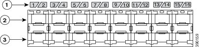
The ports are numbered from 1 to 16 with odd-numbered ports on the upper row and even-numbered ports on the lower row. The following figure shows how the ports and LEDs are numbered.
|
1 |
LEDs |
3 |
Even-numbered ports, left to right: 2, 4, 6, 8, 10, 12, 14, and 16 |
|
2 |
Odd-numbered ports, left to right: 1, 3, 5, 7, 9, 11, 13, and 15 |
Half-Wide Modular Slots
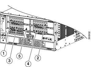
The chassis has four half-wide modular slots that accept pluggable, port cards that can expand the capability of the switch. For more detailed information about the modular port cards and their installation, see the "Installing the Modular Port Card" chapter. The chassis is delivered with modular slot blank covers already installed, which must remain installed if the port cards are not used. The slots are numbered as shown in the following figure.
|
1 |
Half-wide module slot number 1 |
4 |
Half-wide module slot number 4 |
|
2 |
Half-wide module slot number 2 |
5 |
Fixed port card (slot number 5) |
|
3 |
Half-wide module slot number 3 |
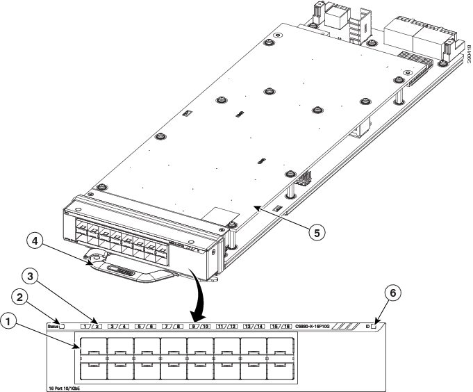
Port Card Overview
Each chassis supports up to four hot-swappable modular port cards that provide uplink ports to connect to other devices. The chassis should only be operated with either a modular port card installed or a blank module installed in the half-modular slots.
|
Port Card Model |
Description |
|---|---|
|
C6880-X-LE-16P10G |
Multirate port card with standard tables. This module has 16 10-Gigabit, 1-Gigabit, or 100BASE-FX fiber-optic slots, which support 1-Gigabit SFPs, 10-Gigabit SFP+, or 100BASE-FX fiber-optic modules. |
|
C6880-X-16P10G |
Multirate port card with XL tables. This module has 16 10-Gigabit, 1-Gigabit, or 100BASE-FX fiber-optic slots, which support 1-Gigabit SFPs, 10-Gigabit SFP+, or 100BASE-FX fiber-optic modules. |
|
C6880-X-CVR-E |
Blank module. |
|
1 |
16 SFP+ or 100BASE-FX SFP ports |
4 |
Extraction handle |
|
2 |
Status LED |
5 |
Port card |
|
3 |
Port LEDs |
6 |
ID (blue beacon LED) |
For a list of supported SFP and SFP+ modules, see the switch data sheet:http://www.cisco.com/c/en/us/products/collateral/switches/catalyst-6880-x-switch/data_sheet_c78-728228.html .
Power Supply Slots
The chassis has two power supply slots that accept either two 3000 W AC-input or two 3000 W DC-input power supplies, or one of each. The chassis is delivered with power supplies pre-installed in the power supply slots. If only one power supply is ordered, then a blank cover is installed in the empty power supply slot, which must remain installed if a power supply is not installed.
Management Port
The management port is a 10/100/1000 copper Ethernet port directly connected to the route processor. It supports TFTP image downloading, network management, SNMP, Telnet, and SSH connections. Flexible NetFlow export is not supported on the management port. The management port is isolated from other ports in the system in a dedicated management VRF; it is not part of the EARL forwarding logic. The management port provides direct access to the CPU, even when the system is heavily loaded.
The management port is a Layer 3 port in host mode, and only accepts traffic that terminates on the router. This port does not route packets between itself and other ports. The port processes only the following packet types and properly enqueues them:
USB Port Type B
The USB 2.0 port Type B serves as a second console connection to the route processor. The USB console port connection uses a USB Type A to Type B cable. The USB console interface speeds are the same as the RJ-45 console interface speeds. Windows PCs need a driver for the USB port.
The USB-prefer mode is the default, but it can be overridden using the command-line interface (CLI). When this port is in USB-prefer mode, the RJ-45 console port will be disabled if both ports are connected. For more information on using the CLI to configure the USB console interface, see the Catalyst 6500 software guide.
USB Type A Port
The USB 2.0 Type A port (disk0) is the only external storage interface for this switch. The port is connected to the route processor, which allows the Cisco IOS software to access the port. The port supports Cisco USB flash drives with capacities from 128 MB to 8 GB (USB devices with port densities of 128 MB, 256 MB, 1 GB, 4 GB, and 8 GB are supported). Cisco IOS software provides standard file system access to the flash device: read, write, erase, and copy. The software also provides the ability to format the flash device with a FAT file system (FAT32 and FAT16).
Console Port
The console port is an RJ-45 port that provides universal asynchronous receiver/transmitter (UART) support to access the route processor with a serial console running at 9600 baud rate with 8 bits for data, no parity bit, and 1 stop bit.
System Reset Button
This recessed access button is used to reset the system. Pressing the button brings down the route processor and all port card modular slots.
Fan Tray
The fan tray is responsible for cooling the entire chassis and interfacing with environmental monitors to trigger alarms when conditions exceed thresholds. The fan tray supports Online Insertion and Removal (OIR).
The fan tray contains four high-efficiency fans with variable speed settings and thermal sensors. If one fan fails, the speed of the others is increased and a minor alarm is triggered. If a major fan tray failure occurs, the system is shut down. The individual fans are not field replaceable; the entire fan tray must be replaced in the event of a major fan tray failure. See Removing the Fan Tray for additional information about the fan.
LED Indicators
You can use the switch LEDs to monitor switch activity and performance. You can also monitor the status of each port on the fixed slot port card, the fan tray assembly, and the power supplies.
Modules inserted in the port card module slots include their own LEDs.
- System Status LED
- Status LED on the Modular Port Card
- System ID LED
- ID LED on the Modular Port Card
- SFP+ Port LEDs
- Management Port LED
- Fan Tray LED
- AC-Input Power Supply LEDs
- DC-Input Power Supply LEDs
System Status LED
The System status LED indicates the status of the system.
|
Color/State |
Description |
|---|---|
|
Off |
System is not operational. |
|
Green |
System is operating normally without alarms. |
|
Amber |
System has triggered a minor environmental alarm. |
|
Red |
System has triggered a major environmental alarm. |
Status LED on the Modular Port Card
The Status LED indicates the status of the modular port card.
|
Color/State |
Description |
|---|---|
|
Off |
Port card is not operational. |
|
Green |
Port card is operating normally without alarms. |
|
Amber |
Port card has triggered a minor environmental alarm. |
|
Red |
Port card has triggered a major environmental alarm, or the system is powering up. |
System ID LED
|
Color/State |
Description |
|---|---|
|
Blinking blue |
The system needs attention. |
ID LED on the Modular Port Card
|
Color/State |
Description |
|---|---|
|
Blinking blue |
The modular port card needs attention. |
SFP+ Port LEDs
Each port on the port card is associated with an LED that indicates status.
|
1 |
LEDs: The first LED in each pair of LEDs indicates the status of the upper (odd-numbered) port below the LEDs, and the second LED in each pair indicates the status of the lower (even-numbered) port. |
3 |
Even-numbered ports, left to right: 2, 4, 6, 8, 10, 12, 14, and 16 |
|
2 |
Odd-numbered ports, left to right: 1, 3, 5, 7, 9, 11, 13, and 15 |
|
Color/State |
Description |
|---|---|
|
Off |
Port is not provisioned. |
|
Amber |
Port is provisioned, but administratively not operational. |
|
Green |
Port is linked up. |
|
Alternating green and amber |
A port fault is detected, or the port beacon has been provisioned by the operator. |
Management Port LED
This table describes the management port LEDs.
|
Color/State |
Description |
|---|---|
|
Off |
Port is not provisioned. |
|
Amber |
Port is provisioned, but administratively not operational. |
|
Green |
Port is linked up. |
|
Alternating green and amber |
A port fault is detected, or the port beacon has been provisioned by the operator. |
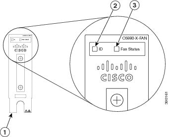
Fan Tray LED
The fan tray includes an ID LED and a Fan Status LED. The different states of the LEDs are described in the following tables.
|
1 |
Front panel |
3 |
Fan Status LED |
|
2 |
ID LED (blue beacon) |
|
Color/State |
Description |
|---|---|
|
Blinking blue |
The fan tray needs attention. |
|
Color/State |
Description |
|---|---|
|
Off |
The fan tray is not receiving power; the fans have stopped. |
|
Green |
All fans are operating normally. |
|
Red |
The fan tray has a failure. |
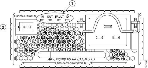
AC-Input Power Supply LEDs
The 3000 W AC-input power supply includes LEDs on the front of the module. The different states of the LEDs are described in the following table.
|
1 |
Location of LEDs on AC-input power supply |
2 |
On/Off switch |
|
LED |
Color/State |
Description |
|---|---|---|
|
IN |
Solid green |
AC input current is at acceptable level. |
|
IN |
Blinking green |
AC input current is outside valid range. |
|
OUT |
Solid green |
DC output current is at acceptable level. |
|
OUT |
Blinking green |
DC output current is outside valid range. |
|
FAULT |
Blinking red |
The unit has failed self-diagnostic test or is not operational. |
|
FAULT |
Off |
Power supply unit is functioning normally. |
|
FAULT |
Solid red |
Malfunction has occurred. |
|
ID |
Blinking blue |
The power supply needs attention, activated by operator. |
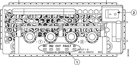
DC-Input Power Supply LEDs
The 3000 W DC-input power supply includes LEDs on the front of the module. The different states of the LEDs are described in the following table.
|
1 |
Location of LEDs on DC-input power supply |
2 |
On/Off switch |
|
LED |
Color/State |
Description |
|---|---|---|
|
IN1 |
Solid green |
Primary DC input current is at acceptable level. |
|
IN1 |
Blinking green |
Primary DC input current is outside valid range. |
|
IN2 |
Solid green |
Secondary DC input current is at acceptable level. |
|
IN2 |
Blinking green |
Secondary DC input current is outside valid range. |
|
OUT |
Solid green |
Output DC current is at acceptable level. |
|
OUT |
Blinking green |
Output DC current is outside valid range. |
|
FAULT |
Off |
Power supply unit is functioning normally. |
|
FAULT |
Blinking red |
The unit has failed self-diagnostic test or is not operational. |
|
FAULT |
Solid red |
Malfunction has occurred. |
|
ID |
Blinking blue |
The power supply needs attention, activated by operator. |
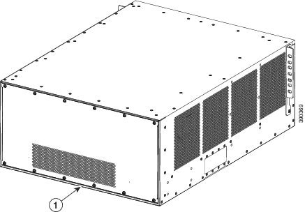
Rear Panel
|
1 |
Rear panel of the switch |
 Feedback