- Preface
- Product Overview
- Preparing for Installation
- Installing the Switch
- Installing and Removing Power Supplies
- Installing the Modular Port Card
- Replacing the Fan Tray
- Technical Specifications
- Module Connectors and Cable Specifications
- Repacking the Switch
- Troubleshooting
- Installing the USB Drivers
Technical Specifications
Switch Specifications
|
Environmental |
Specification |
||
|---|---|---|---|
|
Temperature, operating |
Certified for operation: 32° to 104°F (0° to 40°C) Designed and tested for operation: 32° to 131°F (0° to 55°C)
|
||
|
Temperature, nonoperating and storage |
Chassis unpackaged: –4° to 149°F ( –20° to 65°C) Chassis in protective shipping package: –40° to 158°F ( –40° to 70°C) |
||
|
Thermal transition |
0.9°F (0.5°C) per minute (hot to cold) 0.59°F (0.33°C) per minute (cold to hot) |
||
|
Humidity (RH), ambient (noncondensing operating) |
5% to 90% |
||
|
Humidity (RH), ambient (noncondensing nonoperating and storage) |
5% to 95% |
||
|
Altitude, operating |
Certified for operation: 0 to 6500 ft (0 to 2000 m) Designed and tested for operation: –200 to 10,000 ft ( –60 to 3000 m) |
||
|
Shock and vibration |
Shock Vibration |
||
|
Acoustic noise |
67 dB. International Organization for Standardization (ISO) 7779: Bystander position operating to an ambient temperature of 86°F (30°C). |
||
|
Physical characteristics |
|||
|
Dimensions |
|||
|
Weight |
Chassis only: 48 lb (21.77 kg) Chassis fully configured with 1 fan tray and 2 power supplies: 88 lb (39.92 kg) |
||
|
Airflow |
|
Power Supply Module Specifications
| C6880-X-3KW-AC | C6880-X-3KW-DC | |
|---|---|---|
|
Physical specifications |
||
|
Input voltage range |
85 to 264 VAC |
|
|
Input frequency range |
47 to 63 Hz |
|
|
Input current (each input) |
20 A maximum at nominal line voltage (110 or 220 VAC) |
|
|
Rush-in current |
55 A maximum for one cycle |
50A maximum cold, and 70A maximum hot |
|
Power supply input receptacles |
International Electrotechnical Commission (IEC) 320-C20 |
Dual M6 studs for cable terminal lugs (per KS TCLH!16-6-2AS; 4 each) |
|
Power cord rating |
16A |
— |
|
British thermal units (BTUs) |
||
|
Output holdup time |
20 milliseconds (ms) minimum |
|
|
Environmental conditions |
||
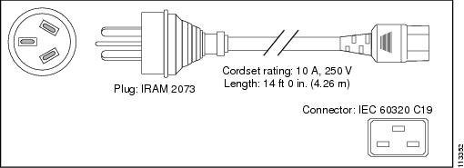
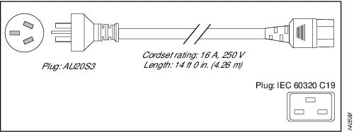
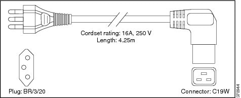
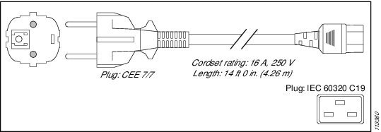
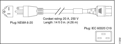
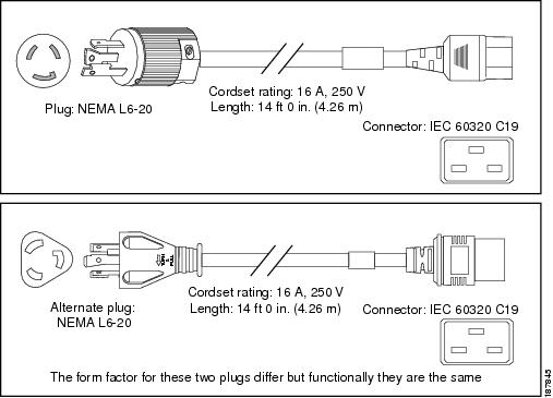
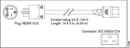
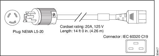
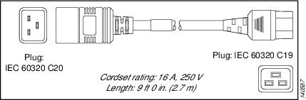
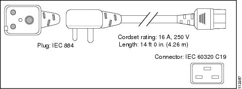
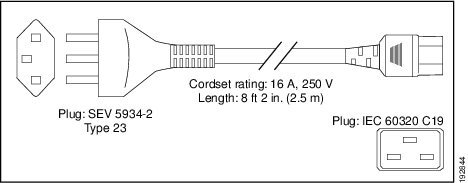
3000 W Power Supply AC Power Cords
The following table lists the specifications for the AC power cords that are available for the 3000 W AC-input power supply. The table also includes references to power cord illustrations.
 Note |
|
Locale |
AC Source Plug Type |
Cordset Rating |
Power Cord Part Number and Reference Illustration |
||
|---|---|---|---|---|---|
|
Argentina |
IRAM 2073 |
16 A, 250 VAC |
 |
||
|
Australia, New Zealand |
AU20S3 |
16 A, 250 VAC |
 |
||
|
Brazil |
EN60320 / C19 |
16 A, 250 VAC |
 |
||
|
People's Republic of China |
GB16C |
16 A, 250 VAC |
 |
||
|
Continental Europe |
CEE 7/7 |
16 A, 250 VAC |
 |
||
|
India |
EN60320/C19 |
16 A, 250 VAC |
 |
||
|
International |
IEC 309 |
16 A, 250 VAC |
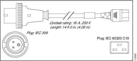 |
||
|
Israel |
SI16S3 |
16 A, 250 VAC |
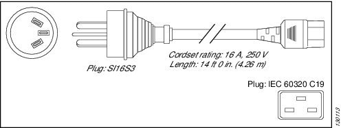 |
||
|
Italy |
CEI 23-16/7 |
16 A, 250 VAC |
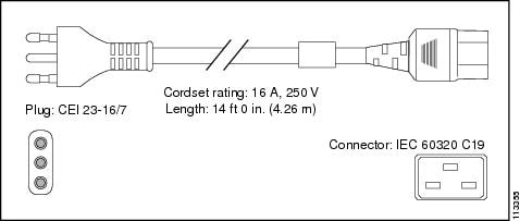
|
||
|
Japan, North America (Nonlocking Plug) 200 to 240 VAC Operation |
NEMA 6-20 |
16 A, 250 VAC |
 |
||
|
Japan, North America (Locking Plug)200 to 240 VAC Operation |
NEMA L6-20 |
16 A, 250 VAC |
|
||
|
Japan, North America 100 to 120 VAC operation 1 |
NEMA 5-20 |
20 A, 125 VAC |
 |
||
|
North America |
NEMA L5 -20 |
20 A, 125 VAC |
 |
||
|
Power Distribution Unit (PDU) 2 |
IEC 60320 C19 IEC 60320 C20 |
16 A, 250 VAC |
 |
||
|
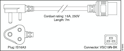
South Africa |
IEC 884-1 |
16 A, 250 VAC |
 |
||
|
Switzerland |
SEV 5934-2 Type 23 |
16 A, 250 VAC |
 |
Fan Module Specifications
|
Physical Specification |
|
|
Dimensions (H x D x W) |
5.75 x 23.28 x 1.65 in. (14.60 x 59.13 x 4.19 cm) |
|
Weight |
6.39 lb (2.90 kg) |
|
Operating Specification |
|
|
Airflow |
250 cfm |
Chassis and Module Power and Heat Values
|
Module Type |
Module Current (A) |
Module Power (Watts) |
AC-Input Power (Watts) |
AC Heat Diss (BTU/HR) |
DC Input Power (Watts) |
DC Heat Diss (BTU/HR) |
| C6880-X-FAN | 4 A | 200 W | 216 W | 737 | 216 | 737 |
| Catalyst 6880-X 3 | 13.2 A | 660 W | 713 W | 2432 BTU/HR | 697 W | 2432 BTU/HR |
| Catalyst 6880-X-LE 4 | 12.6 A | 630 W | 680 W | 2321 BTU/HR | 680 W | 2321 BTU/HR |
 Feedback