- Preface
- Product Overview
- Preparing for Installation
- Installing the Switch
- Installing and Removing Power Supplies
- Installing the Modular Port Card
- Replacing the Fan Tray
- Technical Specifications
- Module Connectors and Cable Specifications
- Repacking the Switch
- Troubleshooting
- Installing the USB Drivers
Installing and Removing Power Supplies
Power Supply Overview
The switch chassis has two slots in which you can install power supplies using any of the following combinations:
-
Two AC-input power supplies
-
Two DC-input power supplies
-
One AC-input power supply and one DC-input power supply
-
One AC-input power supply (leaving the blank cover on the other slot)
-
One DC-input power supply (leaving the blank cover on the other slot)
 Note | If you leave any power supply slots empty, you must ensure that the blank cover (C6800-PS-CV) is installed in that slot to maintain the designed airflow. |
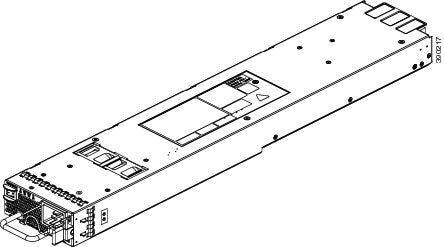
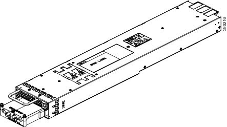
This table lists the power supply models.
| Part Number | Description |
|---|---|
|
C6880-X-3KW-AC |
3000-W AC Power Supply |
|
C6880-X-3KW-DC |
3000-W DC Power Supply |
|
C6800-PS-CVR |
Blank cover |
The power supplies can work together in either of the two modes:
-
Redundant Mode—Each power supply operates at approximately 50 percent of its capacity, no greater than 60 percent and no less than 40 percent. If one power supply fails, the other power supply can provide power for the entire system on its own. This is the default and recommended mode for production.
-
Combined Mode—Each power supply provides approximately 83 percent of its capacity, providing a combined capacity of approximately 167 percent. If one power supply fails, the other power supply might not be able to provide power for the entire system. This is not the recommended mode for operation.
Installing Power Supplies
You follow the same steps to install the AC-input and DC-input power supplies, but you must ground them differently.
Before You Begin
-
The switch chassis must be installed in a cabinet or rack that is secured to the data center.
-
Remove the power supply from its shipping container and remove any packaging.
-
You need the following additional tools and equipment:
-
Nut driver attachment for number 1 Phillips-head screwdriver or ratchet wrench with torque capability (used only for DC-input power supplies).
-
Crimping tool.
-
For the DC-input power supply, you need four power cables sized to reach the DC power source or power interface unit (PIU).
-
Grounding wire — Size this wire to meet local and national installation requirements. For U.S. installations, you must use a 6 AWG copper conductor. For installations outside the U.S., consult your local and national electrical codes. The length of the grounding wire depends on the proximity of the switch to proper grounding facilities.
-
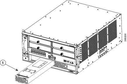
Inserting the Power Supply
To insert the power supply into the chassis, follow these steps:
Connecting to the Power Source
You follow the same steps to install the AC-input and DC-input power supplies, but you must ground them differently.
-
AC-input power supply—It is automatically grounded when you connect its power cable to the power supply and the power source.
-
DC-input power supply—You do not connect the power supply directly to the earth ground.
You use one power cord for each power supply to connect the power supply to its power source.
The number of power sources you use for your power supplies depends on the mode with which you install them:
Before You Begin
Before you connect power supplies to power sources, ensure the following:
-
The chassis is connected to an earth ground. See Establishing the System Ground.
-
You have receptacles for the power sources within reach of the power supply cables.
-
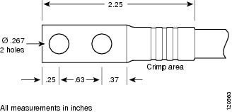
If you are connecting to a DC power, check that you are using 6-AWG power cables to connect to the power supply. The 6-AWG wire size applies to the negative [-], and positive [+] cables that connect to negative and positive slots of the terminal box respectively. You have to procure the power cable.
-
If you are installing more than one DC-input power supply, each must be protected by a dedicated circuit breaker or a fuse that is sized according to the power supply input rating and the local or national electrical code requirements.
-
The power sources are rated as follows:
-
The power supply is already inserted into the chassis.
 Caution | Ensure that the power source is OFF. As an added precaution, place the appropriate safety flag and lockout devices at the source power circuit breaker, or place a piece of adhesive tape over the circuit breaker handle to prevent accidental power restoration while you are working on the circuit. |
 Warning | Before performing any of the following procedures, ensure that power is removed from the DC circuit. Statement 1003 |
Connecting to an AC Power Source
To connect to a power source, follow these steps:
Warning | Take care when connecting units to the supply circuit so that wiring is not overloaded. Statement 1018 |
| Step 1 | Ensure that the power supply switch located on the front of the power supply is set at standby (labeled as 0). | ||
| Step 2 | Plug the power cable into the power supply. Pull down the retention clip over the plug on the power cable. | ||
| Step 3 | Plug the other
end of the power cable into an power source supplied by the data center.
| ||
| Step 4 | Turn the power switch from standby to on (from 0 to 1 as labeled on the power switch). | ||
| Step 5 | Verify that the
power supply is receiving power and outputting DC power by checking that the
INPUT and OUTPUT power supply LEDs are on and the FAULT LED is not on or
flashing. For an explanation of all the power supply LEDs and the conditions
that they indicate, see
AC-input
Power Supply LEDs, page 1-8 and DC-input Power Supply LEDs, page 1-9.
If the Fault LED is flashing red, turn the power switch to standby (labeled as 0), check the AC power connections on the power supply and the AC power source, and then turn the power switch back on (labeled as 1). The Input and Output LEDs for the connected power supplies should be green and the Fault LED should be off. |
Connecting to a DC Power Source
To connect the DC power supply directly to one or two DC power sources, follow these steps:
Warning | Before performing any of the following procedures, ensure that power is removed from the DC circuit.Statement 1003 |
Warning | Hazardous voltage or energy may be present on DC power terminals. Always replace cover when terminals are not in service. Be sure uninsulated conductors are not accessible when cover is in place. Statement 1075. |
| Step 1 | Ensure that the power supply switch located on the front of the power supply is set at standby (labeled as 0). | ||||||||||||
| Step 2 | Turn off the
power at the circuit breakers for the portions of the DC grid power that you
are connecting to and verify that all of the LEDs on the power supplies are
off.
| ||||||||||||
| Step 3 | Size the 6-AWG
power cables to the distance between the power supply and the DC power grid. If
you need to cut the cable, cut it at the end that connects to the DC power
grid, remove 0.75 inch (19 mm) of insulation from the cut ends, and attach them
to the DC power system. Be sure to connect the negative cables to negative
lines and positive cables to positive lines.
| ||||||||||||
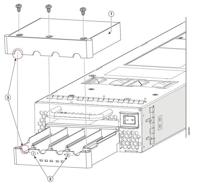
| Step 4 | Remove the three
screws that hold down the safety cover for the terminal box on the front of the
DC power supply and remove the cover.
| ||||||||||||
| Step 5 | Install four
cables (two positive and two negative cables) in the four terminal slots as
follows:
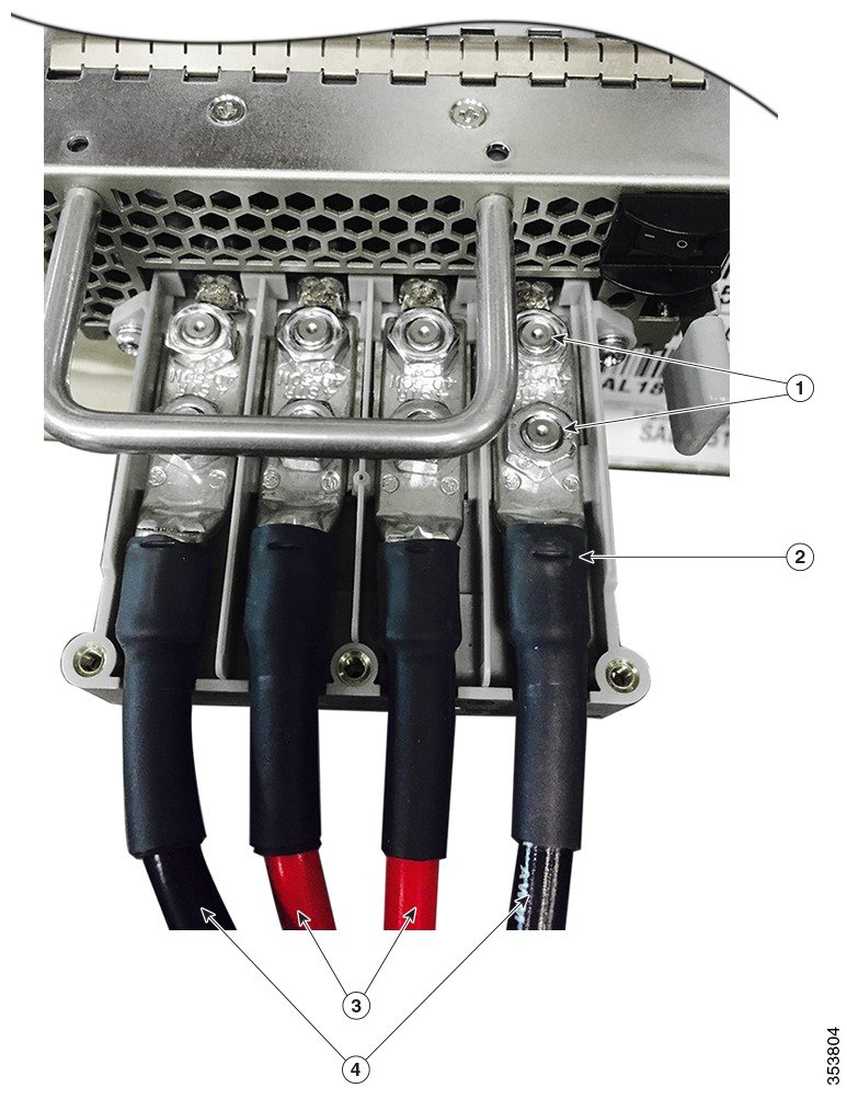
| ||||||||||||
| Step 6 | Install the four
cables from the DC power supply to a DC power sources as follows:
| ||||||||||||
| Step 7 | For the powered down circuits connected to the power supplies, turn on the power at the circuit breaker. The Input 1 (IN1) and Input 2 (IN2) LEDs turn on each connected power supply. | ||||||||||||
| Step 8 | Turn the power
switch on the connected DC power supplies from standby to on (from 0 to 1 as
labelled on the power switch for each power supply).
The LEDs should flash and then the Output LED should turn on in addition to the Input LEDs. If the FAULT LED is on or flashing, call Cisco TAC for assistance. |
Removing Power Supplies
| Step 1 | Turn off the
power to the power supply that you are removing, as follows:
| ||
| Step 2 | Detach the power
and ground cables, as follows:
| ||
| Step 3 | Remove the power
supply from the chassis, as follows:
|
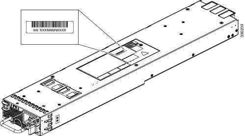
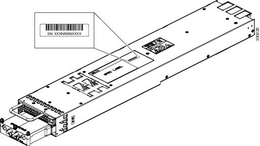
Finding the Serial Number
If you contact Cisco Technical Assistance, you need to know the serial number. These figures show where the serial number is located. You can also use the show version privileged EXEC command to see the serial number.
 Feedback