Cisco SFP and SFP+ Transceiver Module Installation Notes
Available Languages
Table of Contents
Cisco SFP and SFP+ Transceiver Module Installation Notes
Statement 1071—Warning Definition
Installing SFP and SFP+ Transceiver Modules
Removing SFP and SFP+ Transceiver Modules
Standards and Compliance Specifications for SFP and SFP+ Optical Transceivers
Statement 1008—Class 1 Laser Product
Statement 1014—Laser Radiation
Statement 1030—Equipment Installation
Obtaining Documentation and Submitting a Service Request
Cisco SFP and SFP+ Transceiver Module Installation Notes
This installation note provides the installation instructions for the Cisco small form-factor pluggable (SFP) and SFP+ transceiver modules. These transceiver modules are hot-swappable input/output (I/O) devices that plug into 100BASE, 1000BASE and 10GBASE ports (for SFP+), which connect the module port with the fiber-optic or copper network.
Overview
The SFP transceiver modules are hot-pluggable I/O devices that plug into module sockets. The transceiver connects the electrical circuitry of the module with the optical or copper network.
You can use any combination of SFP transceiver modules that your Cisco device supports. The only restrictions are that each port must match the wavelength specifications on the other end of the cable and that the cable must not exceed the stipulated cable length for reliable communications.
Use only Cisco SFP transceiver modules on your Cisco device. Each SFP transceiver module supports the Cisco Quality Identification (ID) feature which allows a Cisco switch or router to identify and validate that the transceiver module is certified and tested by Cisco.
An optical SFP transceiver module is shown in Figure 1.
Figure 1 SFP Transceiver Module (Fiber-Optic LC Connector)
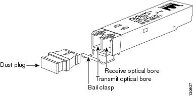

Note![]() SFP transceiver modules that operate with single-strand SMF, have only one optical bore; the other bore is blocked off.
SFP transceiver modules that operate with single-strand SMF, have only one optical bore; the other bore is blocked off.
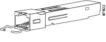
A copper SFP transceiver module in shown in Figure 2.
Figure 2 1000BASE-T SFP Transceiver Module (RJ-45 Connector)
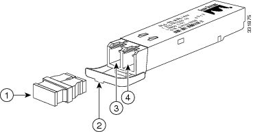
An SFP+ transceiver module is shown in Figure 3.
Figure 3 SFP+ Transceiver Module (Fiber-Optic LC Connector)
The product numbers and brief description of the SFP and SFP+ transceiver modules are listed in Table 1 .
The SFP+ and SFP transceiver module cabling and optical transmit and receive specifications are listed in Table 2 through Table 9 .
|
Core Size (µm)
1
|
Modal Bandwidth (MHz/km)
2
|
||||
|---|---|---|---|---|---|
160 (FDDI) |
|||||
24.86 miles (40 km)3 |
|||||
SFP-10G-ER4 |
||||
SFP-10G-ZR5 |
4.0 (Max) |
|
Core Size (micron)
7
|
|||||
|---|---|---|---|---|---|
722 feet (220 m) |
|||||
MMF8 |
1804 feet (550 m) |
||||
Note![]() For the GLC-ZX-SM, the minimum attenuation between the transmit bore (TX) and the receive bore (RX) is 8 dB. When using shorter distances of single-mode fiber cable, you might need to insert an inline optical attenuator in the link to avoid overloading the receiver.
For the GLC-ZX-SM, the minimum attenuation between the transmit bore (TX) and the receive bore (RX) is 8 dB. When using shorter distances of single-mode fiber cable, you might need to insert an inline optical attenuator in the link to avoid overloading the receiver.
Copper SFP transceiver modules can operate at 10, 100, or 1000 Mbps on some Cisco devices. To find the supported speeds for the 1000BASE-T SFP transceiver modules in your Cisco device, see the Compatibility Matrix for 1000BASE-T Small Form-Factor Pluggable Modules.
Copper 1000BASE-T SFP transceiver modules use standard four twisted-pair, Category 5 cable at lengths up to 328.08 feet (100 meters).
|
Core Size (micron)
9
|
|||||
|---|---|---|---|---|---|
Full width, -20 dB from maximum, with resolution bandwidth (RBW)=0.01 nm |
||||||
See Table 1 for center wavelengths |
||||||
Note![]() Up to 1600 ps/nm chromatic dispersion is supported for fiber links between two Cisco DWDM SFP+ transceiver modules. For connections between a Cisco DWDM SFP+ transceiver module and a Cisco DWDM XENPAK, X2, or XFP transceiver module, limit the chromatic dispersion to 1300 ps/nm.
Up to 1600 ps/nm chromatic dispersion is supported for fiber links between two Cisco DWDM SFP+ transceiver modules. For connections between a Cisco DWDM SFP+ transceiver module and a Cisco DWDM XENPAK, X2, or XFP transceiver module, limit the chromatic dispersion to 1300 ps/nm.
Safety
Safety warnings appear throughout this publication in procedures that may harm you if performed incorrectly or are ignored. A warning symbol precedes each warning statement.
Statement 1071—Warning Definition


Warning![]() Class 1 laser product. Statement 1008
Class 1 laser product. Statement 1008
Warning![]() Laser radiation is present when the system is open and interlocks bypassed. Statement 1014
Laser radiation is present when the system is open and interlocks bypassed. Statement 1014
Warning![]() Only trained and qualified personnel should be allowed to install, replace, or service this equipment. Statement 1030
Only trained and qualified personnel should be allowed to install, replace, or service this equipment. Statement 1030
Required Tools
You will need these tools to install the SFP transceiver module:
- Wrist strap or other personal grounding device to prevent ESD occurrences.
- Antistatic mat or antistatic foam to set the transceiver on.
- Fiber-optic end-face cleaning tools and inspection equipment. For complete information on inspecting and cleaning fiber-optic connections, see the white-paper document at this URL:
http://www.cisco.com/en/US/tech/tk482/tk876/technologies_white_paper09186a0080254eba.shtml
Installing SFP and SFP+ Transceiver Modules
SFP transceiver modules can have three types of latching devices to secure an SFP transceiver module in a port socket:
- Figure 4 shows an SFP transceiver module with a Mylar tab latch.
- Figure 5 shows an SFP transceiver module with an actuator button latch.
- Figure 6 shows an SFP transceiver module that has a bail clasp latch.
- Figure 7 shows an SFP+ transceiver module that has a bail clasp latch.
Determine which type of latch your SFP transceiver module uses before following the installation and removal procedures.

Removing and installing an SFP transceiver module can shorten its useful life. Do not remove and insert SFP transceiver modules more often than is absolutely necessary.
Figure 4 SFP Transceiver Module with a Mylar Tab Latch
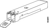
Figure 5 SFP Transceiver Module with an Actuator Button Latch
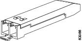
Figure 6 SFP Module with a Bail Clasp Latch
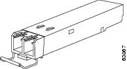
Figure 7 SFP+ Module with a Bail Clasp Latch
To install an SFP transceiver module, follow these steps:
Step 1![]() Attach an ESD-preventive wrist strap to your wrist and to the ESD ground connector or a bare metal surface on your chassis.
Attach an ESD-preventive wrist strap to your wrist and to the ESD ground connector or a bare metal surface on your chassis.
Step 2![]() Remove the SFP transceiver module from its protective packaging.
Remove the SFP transceiver module from its protective packaging.
Note![]() Do not remove the optical bore dust plugs until directed to do so later in the procedure.
Do not remove the optical bore dust plugs until directed to do so later in the procedure.
Step 3![]() Check the label on the SFP transceiver module body to verify that you have the correct model for your network.
Check the label on the SFP transceiver module body to verify that you have the correct model for your network.
Step 4![]() Find the send (TX) and receive (RX) markings that identify the top side of the SFP transceiver module.
Find the send (TX) and receive (RX) markings that identify the top side of the SFP transceiver module.
Note![]() On some SFP transceiver modules, the TX and RX marking might be replaced by arrowheads pointing from the SFP transceiver module connector (transmit direction or TX) and toward the connector (receive direction or RX).
On some SFP transceiver modules, the TX and RX marking might be replaced by arrowheads pointing from the SFP transceiver module connector (transmit direction or TX) and toward the connector (receive direction or RX).
Step 5![]() Position the SFP transceiver module in front of the socket opening.
Position the SFP transceiver module in front of the socket opening.
Note![]() Different Cisco devices have different SFP module socket configurations. Your Cisco device could have either a latch-up or a latch-down orientation. Ensure that you are installing the SFP transceiver module in the correct orientation for your Cisco device. For more details, see the hardware installation instructions that came with your Cisco device.
Different Cisco devices have different SFP module socket configurations. Your Cisco device could have either a latch-up or a latch-down orientation. Ensure that you are installing the SFP transceiver module in the correct orientation for your Cisco device. For more details, see the hardware installation instructions that came with your Cisco device.
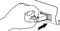
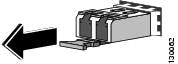
Step 6![]() Holding it as shown in Figure 8, insert the SFP into the socket until you feel the connector latch into place.
Holding it as shown in Figure 8, insert the SFP into the socket until you feel the connector latch into place.
Figure 8 Inserting an SFP Transceiver Module into a Module Socket
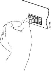
Step 7![]() Press the SFP into the slot firmly with your thumb as shown in Figure 9.
Press the SFP into the slot firmly with your thumb as shown in Figure 9.
Note![]() For SFP transceiver modules equipped with an actuator latch, you must press firmly on both the transceiver faceplate and the actuator button to ensure that the transceiver is properly latched in the socket.
For SFP transceiver modules equipped with an actuator latch, you must press firmly on both the transceiver faceplate and the actuator button to ensure that the transceiver is properly latched in the socket.
Step 8![]() To verify that the SFP is seated and latched properly:
To verify that the SFP is seated and latched properly:
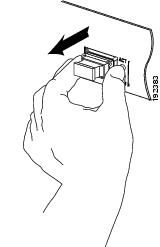
a.![]() Grasp the SFP as shown in Figure 10 and try to remove it without releasing the latch.
Grasp the SFP as shown in Figure 10 and try to remove it without releasing the latch.
b.![]() If the SFP can not be removed, it is installed and seated properly. If the SFP can be removed, reinsert it and press harder with your thumb, repeating if necessary until it is latched securely into the socket.
If the SFP can not be removed, it is installed and seated properly. If the SFP can be removed, reinsert it and press harder with your thumb, repeating if necessary until it is latched securely into the socket.
Figure 10 Verifying SFP Installation
Note For optical SFP transceiver modules, before removing the dust plugs and making any optical connections, observe the following guidelines:
- Always keep the protective dust plugs on the unplugged fiber-optic cable connectors and the transceiver optical bores until you are ready to make a connection.
- Always inspect and clean the LC connector end-faces just before making any connections. See the Tip on this page for a pointer to a fiber-optic inspection and cleaning white paper.
- Always grasp the LC connector housing to plug or unplug a fiber-optic cable.
Step 9![]() Remove the dust plugs from the network interface cable LC connectors. Save the dust plugs for future use.
Remove the dust plugs from the network interface cable LC connectors. Save the dust plugs for future use.
Step 10![]() Inspect and clean the LC connector’s fiber-optic end-faces. See the following Tip for a pointer to a fiber-optic inspection and cleaning white paper.
Inspect and clean the LC connector’s fiber-optic end-faces. See the following Tip for a pointer to a fiber-optic inspection and cleaning white paper.
http://www.cisco.com/en/US/tech/tk482/tk876/technologies_white_paper09186a0080254eba.shtml
Step 11![]() Remove the dust plugs from the SFP transceiver module optical bores.
Remove the dust plugs from the SFP transceiver module optical bores.
Step 12![]() Immediately attach the network interface cable LC connector to the SFP transceiver module.
Immediately attach the network interface cable LC connector to the SFP transceiver module.
Step 13![]() To connect 1000BASE-T SFP transceiver modules to a copper network, follow these substeps:
To connect 1000BASE-T SFP transceiver modules to a copper network, follow these substeps:
a.![]() Insert the Category 5 network cable RJ-45 connector into the SFP transceiver module RJ-45 connector.
Insert the Category 5 network cable RJ-45 connector into the SFP transceiver module RJ-45 connector.
Note![]() When connecting to a 1000BASE-T-compatible server, workstation, or router, use four twisted-pair, straight-through Category 5 cabling for the SFP transceiver module port. When connecting to a 1000BASE-T-compatible switch or repeater, use four twisted-pair, crossover Category 5 cabling.
When connecting to a 1000BASE-T-compatible server, workstation, or router, use four twisted-pair, straight-through Category 5 cabling for the SFP transceiver module port. When connecting to a 1000BASE-T-compatible switch or repeater, use four twisted-pair, crossover Category 5 cabling.
b.![]() Insert the other end of the network cable into an RJ-45 connector on a 1000BASE-T-compatible target device.
Insert the other end of the network cable into an RJ-45 connector on a 1000BASE-T-compatible target device.
Step 14![]() Observe the port status LED:
Observe the port status LED:
- The LED turns green when the SFP transceiver module and the target device have an established link.
- The LED turns amber while the STP feature discovers the network topology and searches for loops. This process takes about 30 seconds, and then the LED turns green.
- If the LED is off, the target device might not be turned on, there might be a cable problem, or there might be a problem with the adapter installed in the target device. See the Troubleshooting section of your switch hardware guide for solutions to cabling problems.
Step 15![]() Reconfigure and reboot the target device if necessary.
Reconfigure and reboot the target device if necessary.
Removing SFP and SFP+ Transceiver Modules
If you are removing an SFP or SFP+ transceiver module, follow these steps:
Step 1![]() Attach an ESD-preventive wrist strap to your wrist and to the ESD ground connector or a bare metal surface on your chassis.
Attach an ESD-preventive wrist strap to your wrist and to the ESD ground connector or a bare metal surface on your chassis.
Step 2![]() Disconnect the network fiber-optic cable or network copper cable from the transceiver module connector. For optical transceiver modules, immediately reinstall the dust plugs in the transceiver module’s optical bores and the fiber-optic cable LC connectors.
Disconnect the network fiber-optic cable or network copper cable from the transceiver module connector. For optical transceiver modules, immediately reinstall the dust plugs in the transceiver module’s optical bores and the fiber-optic cable LC connectors.

Tip![]() For reattachment of fiber-optic cables, note which connector plug is send (TX) and which is receive (RX).
For reattachment of fiber-optic cables, note which connector plug is send (TX) and which is receive (RX).
Step 3![]() Release and remove the transceiver module from the socket connector, as shown in Figure 11, •, Figure 13, or
Release and remove the transceiver module from the socket connector, as shown in Figure 11, •, Figure 13, or
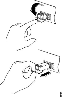
- If the SFP transceiver module has a Mylar tab latch, pull the tab gently in a slightly downward direction until the transceiver disengages from the socket connector, and then pull the SFP transceiver module straight out. Do not twist or pull the Mylar tab because you could detach it from the SFP transceiver module.
Figure 11 Removing an SFP Transceiver Module Equipped with a Mylar Tab
- If the SFP transceiver module has an actuator button latch, gently press the actuator button on the front of the SFP transceiver module until it clicks and the latch mechanism releases the SFP transceiver module from the socket connector. Grasp the actuator button between your thumb and index finger, and carefully pull the SFP transceiver module straight from the module slot.
Figure 12 Removing an SFP Transceiver Module Equipped with an Actuator Button Latch
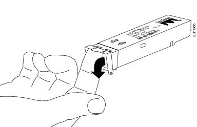
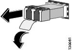
- If the SFP transceiver module has a bail clasp latch, pull the latch out and down to eject the SFP transceiver module from the socket connector. If the bail clasp latch is obstructed and you cannot use your index finger to open it, use a small, flat-blade screwdriver or other long, narrow instrument to open the bail clasp latch. Grasp the SFP transceiver module between your thumb and index finger, and carefully remove it from the socket.
Figure 13 Removing an SFP Transceiver Module Equipped with a Bail Clasp Latch
- The SFP+ transceiver uses a bail clasp style latch which is slightly different than the bail clasp latch for the SFP transceiver. The SFP+ transceiver bail clasp has a small tab protruding down from the bail clasp handle To release the SFP+ bail clasp, push the small tab up and outwards with your index finger to release the bail clasp. Grasp the SFP+ transceiver between your thumb and index finger and carefully remove the transceiver from the socket.
Figure 14 Removing an SFP+ Transceiver Equipped with a Bail Clasp Latch with Tab
Step 4![]() Place the removed transceiver module in an antistatic bag or other protective environment.
Place the removed transceiver module in an antistatic bag or other protective environment.
Standards and Compliance Specifications for SFP and SFP+ Optical Transceivers
This section provides compliance information for the SFP and SFP+ optical transceivers.
FCC Class A Compliance
This equipment has been tested and found to comply with the limits for a Class A digital device, pursuant to part 15 of the FCC rules. These limits are designed to provide reasonable protection against harmful interference when the equipment is operated in a commercial environment. This equipment generates, uses, and can radiate radio-frequency energy and, if not installed and used in accordance with the instruction manual, may cause harmful interference to radio communications. Operation of this equipment in a residential area is likely to cause harmful interference, in which case users will be required to correct the interference at their own expense.
You can determine whether your equipment is causing interference by turning it off. If the interference stops, it was probably caused by the Cisco equipment or one of its peripheral devices. If the equipment causes interference to radio or television reception, try to correct the interference by using one or more of the following measures:
- Turn the television or radio antenna until the interference stops.
- Move the equipment to one side or the other of the television or radio.
- Move the equipment farther away from the television or radio.
- Plug the equipment into an outlet that is on a different circuit from the television or radio. (That is, make certain the equipment and the television or radio are on circuits controlled by different circuit breakers or fuses.)
Modifications to this product not authorized by Cisco Systems could void the FCC approval and negate your authority to operate the product.
Translated Safety Warnings
This section repeats in multiple languages the basic warnings that appear in this document.


Statement 1014—Laser Radiation


Statement 1030—Equipment Installation


Obtaining Documentation and Submitting a Service Request
For information on obtaining documentation, submitting a service request, and gathering additional information, see the monthly What’s New in Cisco Product Documentation, which also lists all new and revised Cisco technical documentation, at:
http://www.cisco.com/en/US/docs/general/whatsnew/whatsnew.html
Subscribe to the What’s New in Cisco Product Documentation as a Really Simple Syndication (RSS) feed and set content to be delivered directly to your desktop using a reader application. The RSS feeds are a free service and Cisco currently supports RSS version 2.0.
 Feedback